Wenzhou Prance Hydraulic Equipment Co., Ltd

High–Low Hydraulic Pump Circuits: Fast Approach and High-Pressure Work
A high-low hydraulic pump circuit combines two pump flows during a lower-pressure movement phase, then unloads the larger-flow pump when the machine enters a higher-pressure work phase. The smaller-flow pump continues supplying the high-pressure demand. This can provide fast approach without requiring the prime mover to drive the full combined flow at the highest working pressure. The benefit depends on the actual cycle: both pumps, the unloading arrangement, isolation, pressure limits, and transitions must be selected as one system.
Two pump photographs do not establish a complete high-low unit. The HDH exterior reference in the illustrations identifies a real catalog product; it does not specify the required displacement pair, pressure rating, control settings, or an approved assembled circuit.
Separate approach demand from work demand
A machine may need substantial flow to move an unloaded actuator quickly, then much less flow while applying force to the workpiece. During approach, the required pressure can be lower because the resisting load is lower. When contact occurs, the pressure requirement rises and the useful movement speed may be intentionally reduced.
Describe both phases with the required flow, pressure, duration, and transition behavior. Include return movement and any intermediate operations. A high-low arrangement is not automatically useful for a machine that needs maximum flow and maximum pressure simultaneously throughout its duty. The circuit concept exploits a difference between phases; it cannot remove the actual hydraulic power required when high flow and high pressure genuinely coincide.
Understand the combined-flow phase
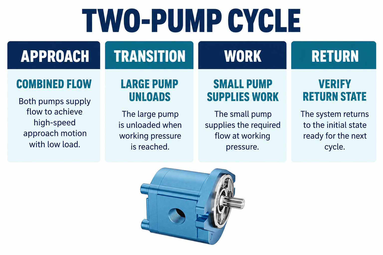
During a typical fast-approach phase, flow from the small and large pump sections reaches the working supply through the intended combining paths. The actual delivered flow depends on displacement, speed, losses, and circuit conditions. The two contributions should be evaluated at the relevant operating point, not simply added from unrelated maximum catalog values.
Isolation elements are important because the two sections may experience different pressure conditions after transition. Confirm the approved arrangement that prevents undesirable reverse flow or discharge through the unloaded branch. A schematic containing two pumps does not by itself establish how the system behaves when one branch unloads. The control and isolation functions must be clear before an appropriate pump pair can be ordered.
Understand the high-pressure work phase
When the transition condition is reached, the larger-flow pump is directed through the approved low-pressure unloading path, while the smaller-flow pump supplies the work demand. The larger section continues to rotate but should not be assumed to consume zero power. Its unloaded pressure loss and other losses remain part of the drive demand and heat balance.
The smaller-flow section and its path must be suitable for the required working pressure and duration. The larger section must remain suitable for its own operating conditions, including any transient exposure during transition. Do not infer that the high-pressure rating of one pump automatically applies to every other component or that a briefly experienced pressure can be ignored because the steady unloaded phase is lower.
Use an illustrative power comparison correctly
Hydraulic power in kilowatts is approximately pressure in bar multiplied by flow in liters per minute, divided by 600. This relationship explains why phase separation can matter. It is not a complete prime-mover selection method because pump efficiency, mechanical losses, unloading loss, starting conditions, and control behavior must also be considered.
For illustration only, consider 10 L/min from one pump and 30 L/min from the other. At 30 bar, their combined 40 L/min represents 2 kW of hydraulic power. During a work phase at 180 bar, the smaller 10 L/min contribution represents 3 kW. If the larger 30 L/min section is unloaded through an illustrative 4-bar pressure drop, that adds 0.2 kW before other losses. Driving the entire 40 L/min at 180 bar would instead represent 12 kW. These assumed numbers explain the concept and are not HDH ratings or a quoted system design.
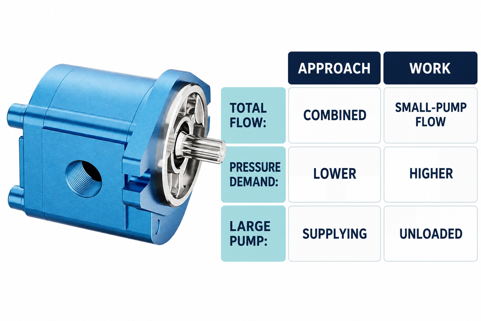
Compare the cycle states
| State | Intended supply behavior | Important verification |
|---|---|---|
| Fast approach | Pump flows combine to support movement | Actual combined flow, pressure loss, and actuator speed |
| Transition to work | Larger section moves to the unloading condition | Stable switching and isolation of the working supply |
| High-pressure work | Smaller section supplies the required working flow | Pressure, duration, pump capability, and drive demand |
| Unloaded large-pump branch | Larger section returns through a suitable low-pressure route | Remaining pressure loss, temperature, and return conditions |
| Return or next cycle | Flow paths change according to the complete circuit | Reset behavior and the actual flow needed for that phase |
This is a functional comparison, not a complete hydraulic schematic or a set of component settings.
Keep unloading and pressure limitation distinct
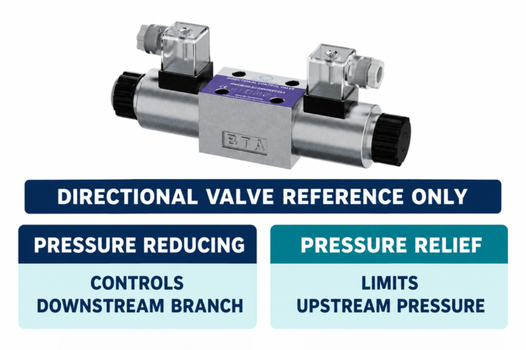
Unloading reduces the pressure demand on a pump flow when that flow is no longer required for the work phase. Pressure limitation addresses the upper pressure conditions of a protected region. The functions can interact in a high-low circuit, but they are not interchangeable merely because both involve pressure-responsive valves.
Review the complete arrangement, including what protects each relevant pressure region in every state. A setting that makes the large pump unload does not automatically establish protection for an isolated work branch or every transition. Likewise, passing unwanted high-pressure flow through a relief path can produce substantial heat. Identify the intended roles rather than adjusting whichever pressure-control element appears easiest to reach.
Review transition stability and reset behavior
The circuit must enter the work phase when required and return to the combined-flow condition when appropriate. Actual switching can be affected by pressure fluctuations, demand changes, pilot conditions, and the selected control design. Repeated switching around a transition can affect motion, noise, heating, and component loading.
Use the approved control characteristics, including any applicable reset or hysteresis behavior. Do not invent a universal difference between unloading and working settings. Define how the machine should behave when the load changes unexpectedly or contact is intermittent, then verify that behavior using the selected components and complete circuit. The approach should address the transition itself rather than judging only two steady gauge readings taken long before and after it.
Select the drive for the complete duty
The prime mover must cover the relevant combined pump demand, not just the nominal work-phase output. Include approach, transition, work, unloaded-branch losses, return conditions, and any simultaneous machine functions. The highest demand may occur in a state that a simple steady work calculation overlooks.
Check the actual pump speed and drive arrangement, including mechanical ratings, coupling, shaft loads, and any tandem-drive limitations where applicable. Two individual pump images are not evidence that they can be connected through one another or mounted as a particular tandem assembly. Use a verified arrangement and document which component or mounting option supports the mechanical power transmission.
Treat unloading losses as heat that still needs management
The larger section can circulate fluid for much of the working phase. Even a relatively low pressure drop across that flow contributes heat, and other system losses can add to it. Calculate the cycle-weighted losses using actual phase durations and conditions instead of describing unloading as entirely loss-free.
Consider fluid temperature, reservoir and cooling arrangements, and the restrictions in the return path. A return circuit that creates more backpressure than expected can change the intended low-loss condition. Avoid judging cooling requirements from the smaller pump’s useful output alone. A useful energy review follows where power goes in each phase, including flow that does no useful actuator work.
Verify the architecture before ordering a pump pair
Provide the required approach speed, working force and speed, phase durations, actuator and return information, available prime mover, fluid, temperature range, and pressure-control concept. Ask the supplier to confirm the exact pump configurations and the conditions under which their performance data applies.
Keep pump selection separate from approval of the entire circuit. The provider of a catalog pump may not be responsible for unloading stability, machine safety, or actuator behavior unless that scope is explicitly included. Request the necessary circuit review and component documentation rather than assuming that purchasing two suitable pumps automatically supplies a validated high-low hydraulic system.
Commission every relevant phase safely
Use the machine’s approved isolation, installation, filling, and commissioning procedures. Account for stored pressure and mechanically supported loads before opening or modifying the circuit. Identify the observations that require stopping, and ensure the intended pressure protection is in place before testing a transition.
Record pump identities, speed, relevant pressures and flows, temperatures, phase timing, and control conditions. Verify fast approach, transition, sustained work, and reset behavior rather than accepting a single successful stroke as the entire test. Compare the actual drive demand and heat behavior with the design review. Retain any limitations, especially where the full duty or temperature range could not be reproduced during the initial commissioning.
Perguntas frequentes
Does a high-low circuit require both pumps to operate at maximum pressure?
Not in the intended separated work phase. The larger-flow section is unloaded while the smaller section supplies higher-pressure work. Each component must nevertheless be checked for its actual continuous and transient exposure.
Is the larger pump switched off during high-pressure work?
Not necessarily. In a common constant-speed arrangement it continues rotating and its flow follows the unloading route. Its losses remain part of drive power and heat generation even though it is no longer supplying the work branch.
Can unloading remove the need for a pressure-limiting function?
No general conclusion of that kind is valid. Review the complete circuit and the pressure regions that need protection in every state. Unloading and pressure limitation are different functions, even when pressure-responsive controls perform them.
Can the example flows be used to order an HDH pair?
No. They are assumed values used to explain phase power. Select the actual configurations from required duty, verified product data, speed, controls, mechanical arrangement, and the approved circuit design.
What should be measured during commissioning?
Measure the conditions needed to verify the intended phases: relevant pressures, flows, speed, temperature, transition and reset behavior, and drive demand where required. Record locations and operating conditions so the results can be compared meaningfully with the design.
Produtos e recursos de engenharia relacionados
The External Gear Pump HDH catalog exterior is used as the real product reference in these explanatory images. It does not establish the approved service method, optional construction, or operating limits for an individual order. Confirm the complete code and its documentation. Related resources: Bomba de Engrenagens Externas HDH, gama de bombas hidráulicas, Bombas hidráulicas em paralelo versus em série: verificações de circuito e de aquisição, Pump Unloading Valve vs Relief Valve: Standby Flow and Heat, Dimensionamento do motor elétrico para bombas hidráulicas: carga, partida e sobrecarga.
Sources and limits of this guide
The university resource supports the component operating principles. NIOSH supplies hazardous-energy prevention context; exact machine isolation and component service requirements still need their approved procedures. Sources explain general operating principles, not performance ratings or optional features of the pictured catalog component.
- NPTEL: Fundamentos de Hidráulica e Pneumática Industrial
- NIOSH: prevenção de lesões causadas por energia perigosa
- NPTEL: two-pump high-low circuit
University lesson: operating principles
NPTEL IIT Guwahati presents Lec 31: Flow control and pressure relief valves. The lesson supports the pump operating principles used in the engineering discussion; it is not a model-specific repair, storage, or installation approval.