Wenzhou Prance Hydraulic Equipment Co., Ltd

Fornecimento interno vs externo de piloto: Comutação a baixa pressão principal
For a hydraulic valve, internal pilot supply takes operating oil from the valve’s main hydraulic path, while external pilot supply uses a separate connection and source. The practical choice depends on whether adequate pilot conditions exist when the main spool must move, including startup, neutral, unloading, and changing load. External supply can separate pilot availability from low main pressure, but it introduces another circuit that must be controlled and protected. Confirm the exact valve schematic and its minimum and maximum pilot requirements. This guide addresses pilot supply for two-stage directional valves, not every device called a pilot-operated valve.
Separate the electrical command from the hydraulic force
In a two-stage directional valve, a small pilot stage directs oil to move the larger main stage. An energized solenoid can operate the pilot stage without proving that the main spool receives sufficient hydraulic force. When a valve clicks but the actuator does not respond, the command, pilot supply, pilot return, and main-flow path require separate checks.
The main spool must overcome its applicable spring forces, friction, and hydraulic forces. The pilot system provides the pressure conditions that produce the required movement. A healthy electrical connector cannot compensate for missing pilot oil. Equally, adequate pilot pressure does not prove that a damaged main spool, incorrect command, or blocked passage will operate correctly.
Keep the distinction visible during troubleshooting. Confirm the electrical instruction and then establish whether the specified hydraulic conditions exist at the correct ports during the attempted movement. Replacing coils repeatedly is unlikely to solve a supply architecture that cannot develop the required pressure at startup.
What internal pilot supply depends on
An internally supplied valve obtains pilot oil through a designed connection from its main circuit, commonly the pressure path in the relevant directional-valve arrangement. This can reduce the need for a separate external supply line. It also ties pilot availability to the main circuit’s condition at the point where the pilot oil is taken.
If the main supply maintains sufficient pressure during all required shifts, internal supply may fit the application. If the circuit unloads to a low pressure, a neutral spool connects pressure to tank, or the supply is delayed during startup, the pilot may not have the conditions needed to shift the main stage. The relevant minimum is valve- and spool-specific.
Some approved designs incorporate a pressure-maintaining arrangement to provide pilot availability. Its location affects which parts of the circuit see the added pressure. Do not add a generic backpressure device from another valve’s example. An unsuitable arrangement can change actuator behavior, heat generation, or load holding. Use the actual machine design and valve documentation.
What external pilot supply adds
External supply feeds the pilot through its designated connection, often identified as X in the applicable schematic. A separate source can maintain the pilot conditions when main-system pressure is low or unstable. The source still needs the pressure, flow capacity, fluid condition, and availability required by the selected valve.
The pilot source must not exceed the control-stage limit simply because the main valve has a higher pressure rating. Check whether regulation, relief protection, filtration, or a particular startup sequence is required. Those are design requirements to verify, not assumptions to infer from the main port size.
External pilot pressure can remain present when the main pump is stopped. If that supply includes an accumulator or another live circuit, isolation of the main pump alone does not remove all stored energy. The maintenance procedure must account for every connected pressure source and verify that the relevant trapped volumes are released.

Pilot supply and pilot drain are different choices
Internal or external supply describes where pilot oil comes from. Internal or external drain describes where the used pilot oil returns. The two decisions are related but are not synonyms. A valve may have a permitted combination that uses external supply with internal return, or another arrangement with a separate return path.
Return pressure can affect the effective pressure available to move the main spool. The applicable relationship depends on the valve design, so read the documented pressure references. A supply gauge showing a plausible number is incomplete evidence if the opposing pilot-return pressure rises during the same event.
This article does not replace a detailed drain-routing review. Its relevance here is that changing supply alone may not cure inadequate actuation. The required pressure difference, maximum return pressure, and connection configuration must remain acceptable after any supply change. Do not combine port plugs and adapter plates from unrelated valve versions.
Compare the operating conditions before selecting supply
The table is a qualitative engineering review aid. It gives no universal minimum pilot pressure and does not authorize a circuit modification.
| Operating condition | Internal-supply question | External-supply question | Evidência a solicitar |
|---|---|---|---|
| Startup before actuator load develops | Is main pressure already sufficient to shift? | Is the separate source available in time? | Startup sequence and pressure trace |
| Neutral with a low-pressure main path | Does pilot supply remain above the required boundary? | Does the source maintain its approved conditions? | Exact neutral schematic and minimum requirement |
| Main circuit pressure fluctuation | Does pilot actuation remain reliable through the change? | Is the source sufficiently independent and stable? | Simultaneous supply and return readings |
| Several functions operate together | Does the pilot feed lose pressure or capacity? | Is shared pilot demand accounted for? | Worst-case operating combination |
| Maintenance shutdown | Which passages retain pressure? | What separate sources remain live? | Isolation and stored-energy procedure |
Use the most demanding switching condition, not only the highest main pressure. A valve can work at high load yet fail to initiate the next cycle after unloading. Conversely, a valve that shifts during a no-load test may not meet the complete operating conditions during a loaded transition.
Diagnose a valve that will not shift at low pressure
Begin with the exact model code, schematic, and installed connection plate. Establish the intended supply and drain arrangement before testing. Incorrect plugs, a mismatched subplate, or a replacement with a different internal connection can prevent the intended pilot path from existing at all.
Then follow the approved test procedure and measure at the designated points during the command. Compare pilot supply and return conditions, main pressure, and any available indication of main-spool response. Use suitably rated instruments and a recording method that can capture the event. A gauge reading taken after pressure has recovered may miss the condition that prevented movement.
If the electrical command is correct but pilot conditions fall outside the documented requirement, investigate the supply path and its source. If pilot conditions are valid, the remaining possibilities include the pilot stage, main stage, mechanical contamination effects, or the machine’s main-flow circuit. The measurement narrows the fault; it does not justify dismantling a pressurized valve.
Do not copy a minimum pilot pressure between models
Different valves and spool configurations can require different actuation conditions. Spring arrangements, flow forces, optional features, and the permitted pressure references affect the applicable limits. A pressure value from a similar-sized catalog valve is not a rating for the installed unit.
Consider a hypothetical case in which the approved documentation specifies a minimum effective pilot difference of 8 bar. If the supply is 12 bar and the relevant return reference is 6 bar, a simple difference is only 6 bar. That would be below the hypothetical requirement. The numbers illustrate why pressure references matter; they are not Prance settings or a general formula for every control-stage design.
Use the actual manufacturer’s relationship and operating chart for the final judgment. Some documents specify supply relative to a named drain reference, while other limits concern absolute port pressure. Record the units and measurement points so that a reviewer can reproduce the comparison without guessing which pressure was meant.

Treat supply conversion as a configuration change
Changing from internal to external pilot supply can require more than connecting a hose. The valve may use defined plugs, passages, seals, and a matching connection plate. Whether a conversion is permitted, who may perform it, and which checks follow must come from the documentation for that exact configuration.
Keep the original setting and connection record before an authorized modification. Confirm pressure protection, the pilot-return arrangement, and the safe condition after a lost electrical command or lost supply. A modification that restores shifting can still alter startup or stopping behavior elsewhere in the machine.
Do not drill passages, remove unidentified plugs, or block a return connection to build pressure experimentally. Secure loads, isolate every source, and release stored energy before opening the assembly. Live-pressure leakage and unexpected movement can cause serious injury. Use the machine’s maintenance and commissioning procedure rather than a generic valve diagram.
Request the right replacement and verify the result
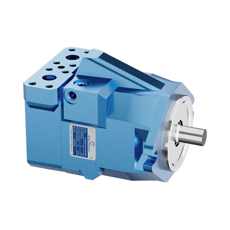
Prance’s 4WRLE pilot-operated proportional-valve product page is relevant to a two-stage valve inquiry. Its exterior photograph and family name do not establish the supply and drain configuration of every available unit. Submit the complete existing code, spool function, plate drawing, pilot arrangement, electrical interface, and operating conditions for a configuration review.
Explain the actual problem: for example, reliable switching under load but no response immediately after unloading. Include synchronized pressure records and the startup sequence where available. This gives the reviewer a defined requirement rather than a request for a valve that merely fits the same bolt pattern.
After replacement or an approved repair, test startup, neutral-to-work transitions, return to neutral, and the relevant combined-function condition. Confirm that the valve shifts within the agreed behavior without unintended actuator motion or excessive pressure. Record the final code and circuit arrangement so that a later service visit does not have to rediscover whether the valve is internally or externally supplied.
Perguntas frequentes
Um solenóide pode clicar enquanto o êmbolo principal permanece imóvel?
Yes. The electrical or pilot-stage response does not prove sufficient hydraulic conditions at the main stage. Check the intended pilot supply and return during the command, following the approved procedure.
O fornecimento externo do piloto é sempre melhor?
No. It can solve an availability problem where main pressure is inadequate, but it adds another source and its protection, routing, and shutdown requirements. Select it only when the complete circuit supports the arrangement.
Fornecimento externo de piloto e drenagem externa são a mesma funcionalidade?
No. Supply identifies the source of pilot oil; drain identifies its return path. Confirm both choices and their permitted combination for the complete valve code.
Can the main valve pressure rating be used for the pilot source?
Not without verification. The pilot stage can have a different maximum limit and pressure reference. Use the specified control-stage requirements and any required protection.
What information is needed for a replacement inquiry?
Provide the complete code, hydraulic schematic, spool function, connection plate, supply and drain arrangement, electrical details, operating sequence, and relevant pressure records. State the low-pressure switching condition explicitly.
Produtos e recursos de engenharia relacionados
The Hydraulic Pilot Operated Proportional Valve 4WRLE provides a relevant product family for a configuration inquiry. The family name and source exterior photograph do not establish the availability of every control or option discussed here. These conceptual illustrations do not depict product internals or establish operating limits. Confirm the complete code and approved documentation. Related resources: Válvula Proporcional Hidráulica de Ação Piloto 4WRLE, Área de válvulas hidráulicas, Quando deve um comprador escolher uma válvula de ação direta ou de operação piloto?, Falhas de feedback de posição da válvula proporcional: Comando vs Posição real.
Sources and limits of this guide
Referências universitárias e governamentais apoiam princípios gerais de engenharia e segurança. Este guia fornece raciocínio de seleção independente e cálculos explicitamente hipotéticos. Nenhum código de controle, configurações ou classificações do fabricante de referência são especificações de um produto Prance. Confirme a configuração completa do pedido.
- NPTEL: Fundamentos de Hidráulica e Pneumática Industrial
- NIOSH: prevenção de lesões por energia perigosa não controlada
- NPTEL IIT: hydraulic directional-valve actuation mechanisms
- VSB Technical University of Ostrava: hydraulic mechanisms and component controls
University lesson: operating principles
NPTEL-NOC IITM presents 5.4 – Directional Control Valves. The lesson supports the directional valve operation and hydraulic actuation used in this discussion; it is not a model-specific performance or installation approval.