Wenzhou Prance Hydraulic Equipment Co., Ltd

-2-1.webp "A10VO45DFR1-52L(01) (2)")
-6.webp "A10VO45DFR1-52L(01) (6)")
-5.webp "A10VO45DFR1-52L(01) (5)")
-4.webp "A10VO45DFR1-52L(01) (4)")
-3.webp "A10VO45DFR1-52L(01) (3)")
-1.webp "A10VO45DFR1-52L(01) (1)")
High Pressure Variable Displacement Piston Pump A10VSO 52 Series
1.Variable pump with axial piston rotary group in swashplate design for hydrostatic drives in open circuit.
2.Flow is proportional to drive speed and displacement.
3.The flow can be infinitely varied by adjusting the swashplate angle.
4.Stable bearing for long service life
5.High permissible drive speed
6.Favorable power-to-weight ratio – compact dimensions
Detailed description
This is a variable pump built with an axial piston rotary group adopting swashplate design, tailor-made for hydrostatic drive systems in open circuit hydraulic applications. The pump’s output flow is strictly proportional to the input drive speed and its own displacement capacity. By precisely adjusting the swashplate inclination angle, the flow rate can achieve stepless infinite variation, which flexibly adapts to different flow regulation requirements of hydraulic systems. It is equipped with high-performance stable bearings, effectively reducing mechanical wear and friction loss, and greatly extending the overall service life of the pump unit. The product supports high permissible drive speed, delivering efficient and powerful hydraulic output under high-speed operating conditions. Meanwhile, it features a favorable power-to-weight ratio and compact overall dimensions, saving installation space, lowering equipment overall weight, and offering outstanding adaptability for both mobile machinery and industrial fixed hydraulic equipment layouts.
Type code series 52
| 01 | 02 | 03 | 04 | 05 | 06 | 07 | 08 | 09 | 10 | 11 | 12 | ||
| A10V(S) | ○ | / | 32 | - | v |
Axial piston unit
| 10 | 28 | 45 | 60 | 85 | |||
| 01 | Swashplate design, variable, nominal pressure 250 bar, maximum pressure 315 bar | ● | - | - | - | - | A10VS |
| - | ● | ● | ● | ● | A10V |
Operation mode
| 02 | Pump, open circuit | ○ |
Size(NG)
| 03 | Geometric displacement, see table of values on page 10 | 10 | 28 | 45 | 60 | 85 |
Control device
| 04 | Pressure controller | hydraulic | ● | ● | ● | ● | ● | DR | ||||
| with flow controller | hydraulic | X-T open | ● | ● | ● | ● | ● | DFR | ||||
| X-T plugged | with flushing function | ● | ● | ● | ● | ● | DFR1 | |||||
| without flushing function | ● | ● | ● | ● | ● | DRSC | ||||||
| with pressure cut-off | hydraulic | remotely controlled | ● | ● | ● | ● | ● | DRG | ||||
| electrical | negative control | U=12V | ● | ● | ● | ● | ● | ED71 | ||||
| U=24V | ● | ● | ● | ● | ● | ED72 | ||||||
| electrical | positive control | U=12V | ● | ● | ● | ● | ● | ER71 | ||||
| U=24V | ● | ● | ● | ● | ● | ER72 | ||||||
| Differential pressure control | electric control (negative control) | ● | ● | ● | ● | ○ | EF..1) | |||||
Series
| 10 | 28 | 45 | 60 | 85 | |||
| 05 | Series 5, index 2 | ● | ● | ● | ● | ● | 52 |
Direction of rotation
| 06 | Viewed on drive shaft | clockwise | R |
| counter-clockwise | L |
Sealing material
| 07 | FKM (fluoroelastomer) | V |
Drive shaft
| 08 | Splined shaft
IS0 3019-1 |
standard shaft | ● | ● | ● | ● | ● | S |
| similar to shaft "S" however for higher input torque | - | ● | ● | ● | ● | R | ||
| reduced diameter, limited suitability for through drive | ● | ● | ● | ● | ● | U | ||
| similar to shaft "U", however for higher torque only conditionally suitable for mounting with through drive. | - | ● | ● | ● | ● | W | ||
| Parallel keyed shaft DIN 6885 limited suitability for through drive | ● | - | - | - | - | P | ||
Mounting flange
| 09 | ISO 3019-2 (ISO) | 2-hole | ● | - | - | - | - | A |
| ISO 3019-1 (SAE) | 4-hole | ● | ● | ● | ● | ● | C | |
| 4-hole | - | - | - | ● | - | D |
Working port
| 10 | 28 | 45 | 60 | 85 | |||||
| 10 | SAE flange ports Fastening thread metric | rear | not for through drive | - | ● | ● | ● | ● | 11 |
| laterally opposite | for through drive | - | ● | ● | ● | ● | 12 | ||
| at side,offset 90° | not for through drive;
available for counter-clockwise rotation only |
- | - | ● | - | - | 13 | ||
| Threaded port metric | rear | not for through drive | ● | - | - | - | - | 14 |
Through drive
| 11 | Flange IS0 3019-1
Diameter |
Hub for splined shaft1)
Diameter |
045 | 071 | 100 | 140 | 180 | ||
| without through drive | ● | ● | ● | ● | ● | N00 | |||
| 82-2 (A) | 5/8 in | 9T 16/32DP | - | ● | ● | ● | ● | K01 | |
| 3/4 in | 11T 16/32DP | - | ● | ● | ● | ● | K52 | ||
| 101-2 (B) | 7/8in | 13T 16/32DP | - | ● | ● | ● | ● | K68 | |
| 1in | 15T 16/32DP | - | - | ● | ● | ● | K04 | ||
| 127-4 (C) | 1 1/4in | 14T 12/24DP | - | - | - | ● | ● | K15 | |
| 1 1/2 in | 17T12/24DP | - | - | - | - | ● | K16 | ||
| 127-2 (C) | 1 1/4 in | 14T 12/24DP | - | - | - | - | ● | K07 | |
| 1 1/2 in | 17T 12/24DP | - | - | - | - | ● | K24 | ||
Connectors for solenoids
| 12 | Without connector (without solenoid, only for hydraulic controls, without signs) | ● | ● | ● | ● | ● | |
| DEUTSCH - molded connector, 2-pin, without suppressor diode (for electric control) | - | ● | ● | ● | ● | P |
•= Available ○ = On request - = Not available
Technical data
| Size | NG | 10 | 18 | 28 | 45 | 60 | 63 | 72 | 85 | 100 | ||
| Displacement, geometric, per revolution | Vg max | cm3 | 10.5 | 18 | 28 | 45 | 60 | 63 | 72 | 85 | 100 | |
| Rotational speed
maximum1) |
at Vg max | nnom | rpm | 3600 | 3300 | 3000 | 26004) | 2700 | 2600 | 2600 | 2500 | 2300 |
| at Vg <Vg max 2) | nmax adm. | rpm | 4320 | 3960 | 3600 | 3120 | 3140 | 3140 | 3140 | 3000 | 2500 | |
| Flow | at nnom and Vg max | qv | I/min | 37 | 59 | 84 | 117 | 162 | 163 | 187 | 212 | 230 |
| at nE = 1500 rpm | qvE | I/min | 15 | 27 | 42 | 68 | 90 | 95 | 108 | 128 | 150 | |
| Power | With Nnom, Vg max
and Δp = 250 bar |
P | kW | 16 | 25 | 35 | 49 | 65 | 68 | 77 | 89 | 96 |
| at nE= 1500 rpm | PE | kW | 7 | 11 | 18 | 28 | 37 | 39 | 45 | 53 | 62 | |
| Torque | at Vg max
and Δp = 250 bar |
M | Nm | 42 | 71 | 111 | 179 | 238 | 250 | 286 | 338 | 398 |
| at Vg max
and Δp = 100 bar |
M | Nm | 17 | 29 | 45 | 72 | 95 | 100 | 114 | 135 | 159 | |
| Rotary stiffness Drive shaft | S | c | Nm/rad | 9200 | 11000 | 22300 | 37500 | 65500 | 65500 | 65500 | 143000 | 143000 |
| R | c | Nm/rad | - | 14800 | 26300 | 41000 | 69400 | 69400 | 69400 | 152900 | 152900 | |
| U | c | Nm/rad | 6800 | 8000 | 16700 | 30000 | 49200 | 49200 | 49200 | 102900 | 102900 | |
| W | c | Nm/rad | - | - | 19900 | 34400 | 54000 | 54000 | 54000 | 117900 | 117900 | |
| P | c | Nm/rad | 10700 | - | - | - | - | - | - | - | - | |
| Moment of inertia of the rotary group | JTW | Kgm2 | 0.0006 | 0.0009 | 0.0017 | 0.003 | 0.0056 | 0.0056 | 0.0056 | 0.012 | 0.012 | |
| Maximum angular acceleration3) | α | rad/s2 | 8000 | 6800 | 5500 | 4000 | 3300 | 3300 | 3300 | 2700 | 2700 | |
| Case volume | V | L | 0.2 | 0.25 | 0.3 | 0.5 | 0.8 | 0.8 | 0.8 | 1 | 1 | |
| Weight without through drive (approx.)
Weight with through drive (approx.) |
m | kg | 8 | 11.5 | 15 | 18 | 22 | 22 | 22 | 36 | 36 | |
| - | 13 | 18 | 24 | 28 | 28 | 28 | 45 | 45 | ||||
Determining the operating characteristics
| Flow | qv=(Vg ∙ n ∙ ηv) / 1000 | I/min |
| Torque | M=(Vg ∙ Δp) /(20 ∙ π ∙ ηhm) | Nm |
| Power | P=(2π ∙ M ∙ n)/60000=(qv ∙ Δp)/(600 ∙ ηt) | kW |
Key
Vg Displacement per revolution in [cm3]
Δp Differential pressure [bar]
n Rotational speed [rpm]
ηv Volumetric efficiency
ηhm Hydraulic-mechanical efficiency
ηt Total efficiency (ηt= ηv*ηhm)
1) The values are applicable:
- At an abs. pressure pabs = 1 bar at the suction port S
- for the optimum viscosity range from Vopt = 36 to 16 mm2/s
- with hydraulic fluid on the basis of mineral oils
2)See diagram on page 9 at speed increase up to nmax adm.
3)The data are valid for values between the minimum required and maximum permissible rotational speed. It applies for external stimuli (e.g. diesel engine 2 to 8 times rotary frequency, cardan shaft twice the rotary frequency). The limit value is only valid fora single pump. The load capacity of the connection parts must be considered.
Permissible radial and axial forces on the drive shaft
| Size | NG | 10 | 18 | 28 | 45 | 60/63 | 72 | 85 | 100 | ||
| Maximum radial force at a/2 |  |
Fq max | N | 250 | 350 | 1200 | 1500 | 1700 | 1500 | 2000 | 2000 |
| Maximum axial force | ±Fax max | N | 400 | 700 | 1000 | 1500 | 2000 | 1500 | 3000 | 3000 | |
Permissible input and through-drive torques
| Size | 10 | 18 | 28 | 45 | 60/63 | 72 | 85 | 100 | |||
| Torque at Vg max and Δp = 250 bar1) | Mmax | Nm | 42 | 71 | 111 | 179 | 250 | 321 | 338 | 398 | |
| Maximum input torque on drive shaft2) | |||||||||||
| S | ME max | Nm | 126 | 124 | 198 | 319 | 630 | 630 | 1157 | 1157 | |
| ∅ | in | 3/4 | 3/4 | 7/8 | 1 | 1 1/4 | 1 1/4 | 1 1/2 | 1 1/2 | ||
| R | ME max | Nm | - | 160 | 250 | 400 | 650 | 650 | 1215 | 1215 | |
| ∅ | in | - | 3/4 | 7/8 | 1 | 1 1/4 | 1 1/4 | 1 1/2 | 1 1/2 | ||
| U | ME max | Nm | 60 | 59 | 105 | 188 | 306 | 306 | 628 | 628 | |
| ∅ | in | 5/8 | 5/8 | 3/4 | 7/8 | 1 | 1 | 1 1/4 | 1 1/4 | ||
| W | ME max | Nm | - | - | 140 | 220 | 396 | 383 | 650 | 650 | |
| ∅ | in | - | - | 3/4 | 7/8 | 1 | 1 | 1 1/4 | 1 1/4 | ||
| P | ME max | Nm | 90 | - | - | - | - | - | - | - | |
| ∅ | mm | 18 | - | - | - | - | - | - | - | ||
| Maximum through-drive torque | |||||||||||
| S | MD max | Nm | - | 108 | 160 | 319 | 484 | 484 | 698 | 698 | |
| R | MD max | Nm | - | 120 | 176 | 365 | 484 | 484 | 698 | - | |
| U | MD max | Nm | - | 59 | 105 | 188 | 306 | 306 | 628 | 628 | |
| W | MD max | Nm | - | - | 140 | 220 | 396 | 383 | 650 | 650 | |
Distribution of torques
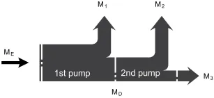
| Torque at 1st pump | M1 |
| Torque at 2nd pump | M2 |
| Torque at 3rd pump | M3 |
| Input torque | ME=M1+M2+M3 |
| ME < ME max | |
| Through∙drive torque | MD=M2+M3 |
| MD < MD max |
1)Efficiency not considered
2) For drive shafts with no radial force
