Wenzhou Prance Hydraulic Equipment Co., Ltd

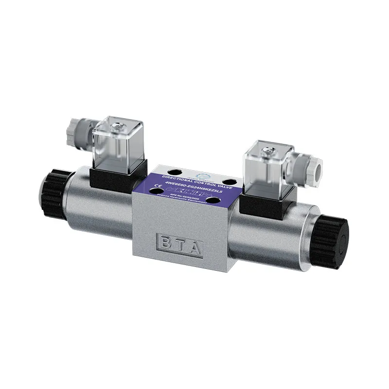
Hydraulic Directional Control Valve: Types, Symbols & Applications
Hydraulic Directional Control Valve — Directional control valves route fluid between pump, actuator, and tank ports; spool type, actuation, and mounting must match flow, pressure drop, and electrical interface. This guide focuses on hydraulic sizing, application fit, and procurement documentation for export and industrial buyers. Cross-check public data on prancehydraulic.com and confirm project limits with your design engineer.
Part 1. Core Concepts and Working Principle
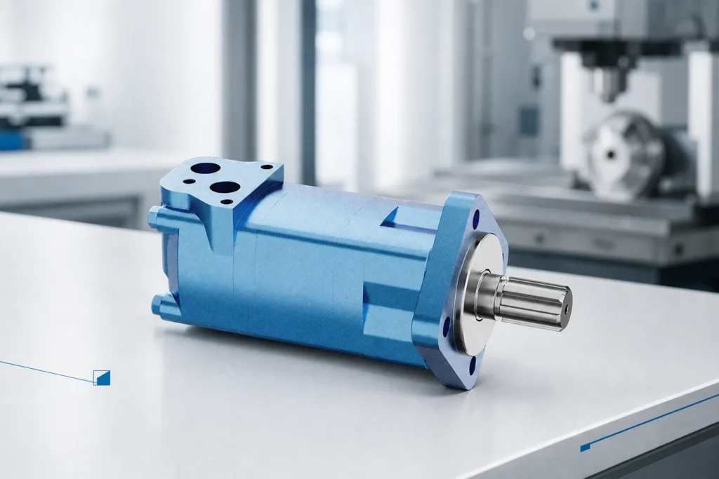
This section explains how hydraulic directional control valve fits in open-circuit and industrial hydraulic systems as a positive-displacement component.
Buyers should confirm displacement, rated pressure, speed limits, and fluid compatibility before comparing quotations.
Misalignment between catalog peaks and actual duty cycle is a common source of overheating, noise, and early wear.
Match valve flow rating to expected circuit flow at working pressure drop, not only nominal port size.
Solenoid voltage, connector type, and manual override options must match the machine electrical standard.
Subplate and cavity standards (NG6/NG10/CETOP) must align with manifold design before purchase.
Review Prance Hydraulic product line for directional and proportional options that fit your control architecture.
Include duty pressure, flow, fluid type, ambient temperature, and duty cycle in every RFQ.
Confirm imperial and metric port and shaft dimensions for export machines before fabrication.
Define warranty response, spare parts lead time, and who performs startup in the purchase order.
Tip: Request duty-point data sheets, not marketing summaries alone.
Part 2. Specifications, Limits, and Selection Criteria
Continuous versus intermittent pressure ratings must match your relief valve setting and load cycle.
Inlet conditions, filtration (ISO 4406), and fluid viscosity at cold start affect both performance and service life.
Mounting, shaft, rotation, and port orientation should be frozen before mechanical design sign-off.
Proportional valves may need amplifier cards and tuning—budget commissioning time accordingly.
Pilot-operated valves depend on minimum pilot pressure; verify at low system load.
Cartridge valves require cavity tools and torque specs; field service differs from inline bodies.
Spool overlap and neutral function (A, B, T blocked or open) affect load holding and safety.
Include duty pressure, flow, fluid type, ambient temperature, and duty cycle in every RFQ.
Confirm imperial and metric port and shaft dimensions for export machines before fabrication.
Define warranty response, spare parts lead time, and who performs startup in the purchase order.
| Parameter | What to verify | Typical source |
|---|---|---|
| Pressure / flow | Duty point vs continuous rating | Manufacturer curve |
| Speed range | Motor/pump RPM limits | Datasheet |
| Fluid / temperature | Viscosity window | O&M manual |
| Filtration | Inlet cleanliness target | ISO 4406 / OEM spec |
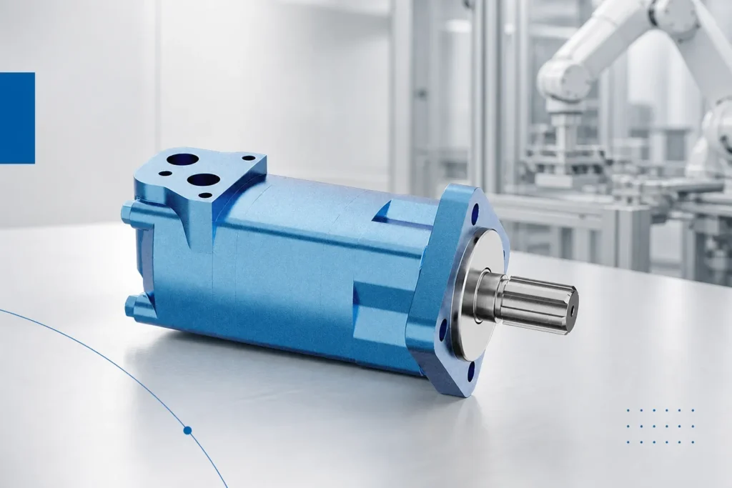
Important: Do not operate hydraulic pumps or motors without adequate inlet supply and relief protection—cavitation and over-pressure cause rapid wear and safety hazards.
Part 3. Field Application and Installation Notes
On site, Hydraulic Directional Control Valve selection must match actual piping, tank, and relief architecture—not spreadsheet assumptions alone.
Verify rotation, mounting torque, and port orientation before first pressurization.
Inlet vacuum and return backpressure limits are common root causes of premature failure.
Document startup pressure, temperature, and case drain (if applicable) at acceptance.
Functional test every section at working pressure before production release.
Document coil duty rating (continuous vs intermittent) for machines with long hold times.
Escalate servo or high-dynamic applications through Prance Hydraulic engineering contact with full circuit data.
Keep spare coils and O-rings for the exact valve series on the critical spares list.
Include duty pressure, flow, fluid type, ambient temperature, and duty cycle in every RFQ.
Confirm imperial and metric port and shaft dimensions for export machines before fabrication.
Define warranty response, spare parts lead time, and who performs startup in the purchase order.
| Check item | Why it matters | Typical owner |
|---|---|---|
| Inlet / return line size | Prevents cavitation and overheating | Hydraulic designer |
| Relief setting vs component rating | Prevents over-pressure damage | Commissioning |
| Filtration beta ratio | Protects clearances | Maintenance |
| As-built schematic | Supports future service | Owner O&M |
Tip: Photograph nameplates and port labels during acceptance—they are required for correct spare parts.
Tip: Archive baseline pressure, flow, and temperature readings after commissioning.
Part 4. Documentation and Handover Checklist
Industrial acceptance relies on documented ratings and test evidence—not verbal assurances.
Use the tables below as a hydraulic RFQ and handover starting point; your EPC contract may require more.
Cross-check related Prance Hydraulic product pages for public specifications and request gaps in writing.
Normalize Incoterms, warranty, and commissioning scope when comparing suppliers.
| Document / item | Purpose | When to request |
|---|---|---|
| Performance / displacement curve | Verify flow at speed and pressure | Before purchase order |
| Mounting / shaft / port drawing | Mechanical and piping design | Design phase |
| Filtration and fluid spec | Prevent premature wear | Before first fill |
| Spare seal / kit list | Lifecycle planning | Contract negotiation |
| Commissioning checklist | Acceptance at duty point | Before handover |
| Application | Typical component | Selection note |
|---|---|---|
| Mobile construction auxiliaries | Gear or piston pump | Confirm pressure, speed, and tank size |
| Industrial power unit | Gear, vane, or piston pump | Match displacement to motor RPM and relief setting |
| Crane / drill rig drives | Piston motor (e.g. A6VM class) | Check case drain and speed limits |
| Wheel / conveyor drive | Orbit motor | Size displacement for torque at low speed |
| Direction / proportional control | Solenoid or proportional valve | Match flow, pressure drop, and electrical interface |
Tip: Store factory test reports with the component serial number.
Tip: Keep fluid analysis reports with the machine maintenance file.
Part 5. Commissioning, Monitoring, and Long-Term Operations
Commissioning should verify performance at working pressure and speed, not only correct rotation direction.
Log baseline pressure, temperature, case drain (if fitted), and noise at acceptance load.
Train maintenance on lockout/tagout, filter change intervals, and fluid sampling procedures.
Trend case drain and temperature in service—step changes often precede seal or bearing failure.
After circuit modifications, re-verify relief settings and hose ratings before returning to production.
Keep spare seal kits and critical filters based on lead time and downtime cost.
Tip: Re-sample fluid after the first 100 hours if the system was flushed at commissioning.
Recommended Prance Hydraulic Products
For project support, explore our related product line, solution options, and OEM/ODM capabilities on prancehydraulic.com.
FAQ
What is a hydraulic directional control valve?
Confirm hydraulic directional control valve ratings, flow, and mounting on the manufacturer datasheet for your duty pressure and circuit architecture.
What are 4/3 and 4/2 directional valves?
Confirm hydraulic directional control valve ratings, flow, and mounting on the manufacturer datasheet for your duty pressure and circuit architecture.
How do solenoid directional valves work?
Confirm hydraulic directional control valve ratings, flow, and mounting on the manufacturer datasheet for your duty pressure and circuit architecture.
What is subplate mounting for hydraulic valves?
Confirm hydraulic directional control valve ratings, flow, and mounting on the manufacturer datasheet for your duty pressure and circuit architecture.
How do you size a directional control valve?
Confirm hydraulic directional control valve ratings, flow, and mounting on the manufacturer datasheet for your duty pressure and circuit architecture.
What causes valve spool sticking or drift?
Confirm hydraulic directional control valve ratings, flow, and mounting on the manufacturer datasheet for your duty pressure and circuit architecture.
What is pilot pressure for directional valves?
Confirm hydraulic directional control valve ratings, flow, and mounting on the manufacturer datasheet for your duty pressure and circuit architecture.
When use manual vs solenoid directional valves?
Confirm hydraulic directional control valve ratings, flow, and mounting on the manufacturer datasheet for your duty pressure and circuit architecture.
References
Ready to discuss your project? Contact Prance Hydraulic engineering support with your project parameters and technical requirements.