Wenzhou Prance Hydraulic Equipment Co., Ltd

Hydraulic Valve Factory Acceptance Test: Buyer Checklist
What a hydraulic valve factory acceptance test should establish
A hydraulic valve factory acceptance test should establish that the identified valve meets agreed functional and performance requirements under recorded test conditions. The buyer and supplier should agree the scope before manufacture or shipment: identity, valve symbol, pressure and flow conditions, fluid temperature, electrical interface, leakage definitions, test methods and acceptance limits. A report saying only that the valve passed is insufficient for comparing results or commissioning a machine. Factory testing also does not qualify every installation. The finished machine still requires integration checks, safe commissioning and verification under its actual duty. Use the factory report to make those later checks more focused and traceable.
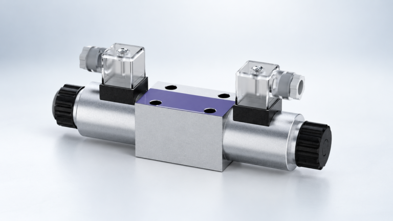
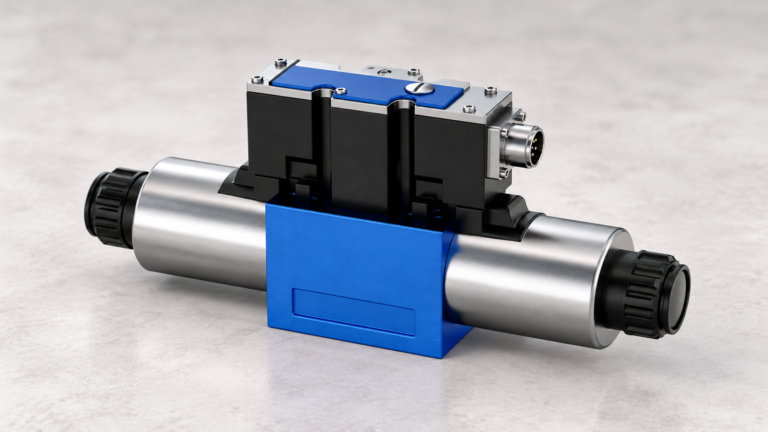
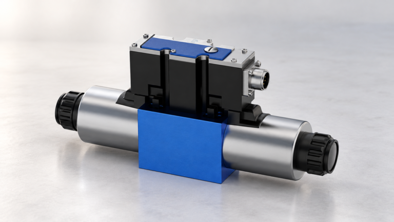
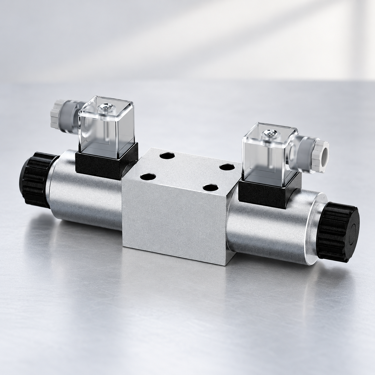
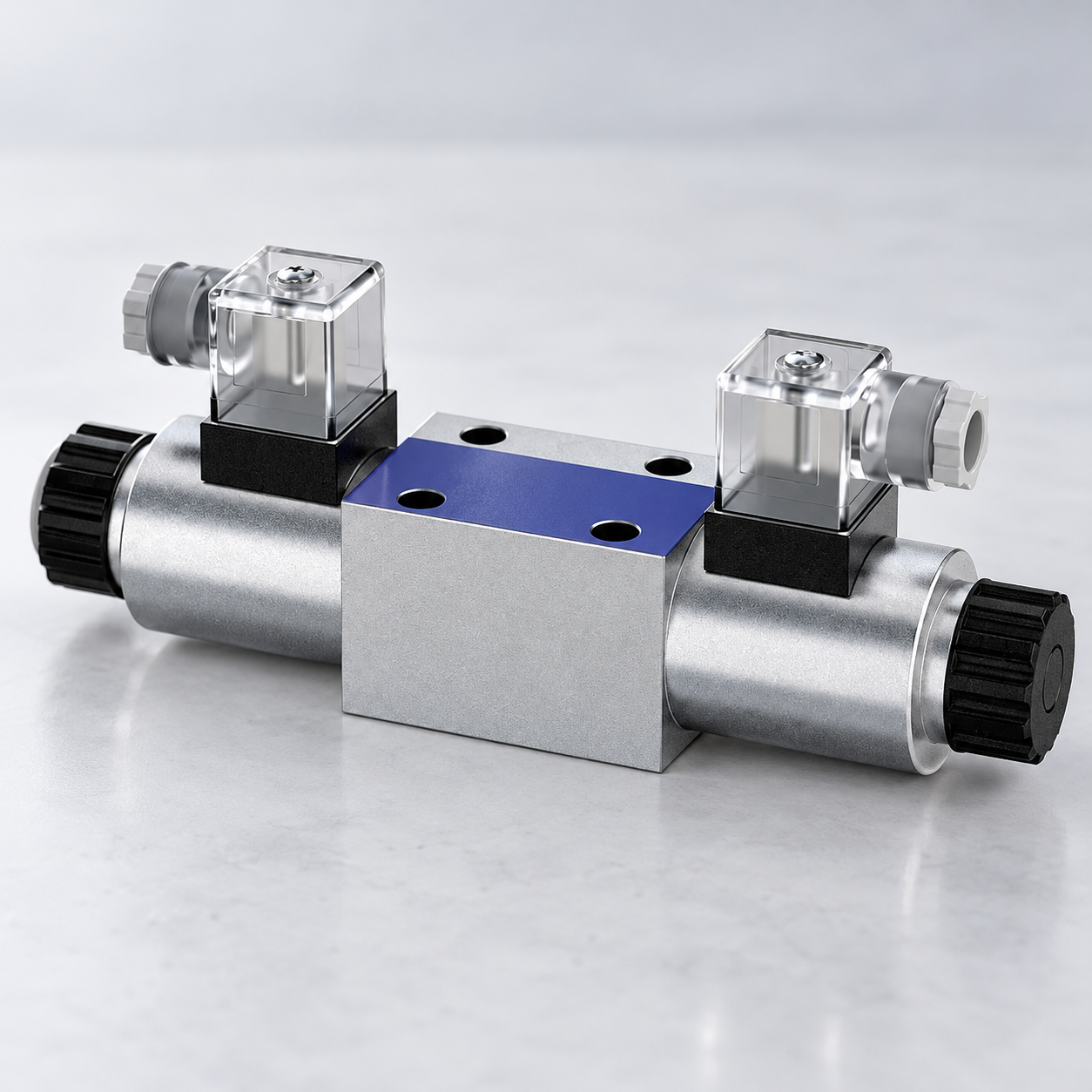
This checklist describes how to specify and review evidence. It supplies no universal pressure, leakage or response limit. Such limits belong to the selected valve configuration, the purchase agreement and applicable documentation. The exterior product illustrations help identify a directional valve assembly; they do not show an energized test or prove its internal spool configuration.
Agree the acceptance scope before issuing an order
Start with the machine's required functions. State which ports should communicate in each commanded position, the neutral condition and the role of any separate holding or protective components. A valve that shifts successfully can still be unsuitable if its center configuration changes the intended circuit. Give the supplier the circuit symbol and complete order requirements rather than only a photograph of the old assembly.
Separate mandatory acceptance checks from optional characterization. Routine identity and functional checks answer whether the ordered assembly was supplied. Detailed dynamic measurements can require different instruments and test arrangements. Agree whether every unit, a selected sample or a qualified design is tested for each requirement. Record the basis of any sampling agreement so a buyer does not mistake one development report for testing of every shipped valve.
Identify the witness arrangements, report format and handling of deviations. If remote witnessing is used, agree how the operator shows the serial number, instruments, connections and live readings. Photographs and recordings can support traceability, but they do not replace a defined method or a calibrated measurement.
Confirm identity and documentation
Record the complete valve order code, serial or batch identification, electrical configuration and spool option. Compare markings with the order, drawing and circuit symbol. Ask the supplier to identify any change from the approved configuration before testing. A partly matching code can conceal a difference in voltage, connector, seal option or neutral paths.
Review drawings for mounting interfaces, ports, electrical connections and permitted operating conditions. State the document revision in the report. If a component has integrated electronics, record its version and configuration when relevant to the measurements. A later electronics or spool change may invalidate direct comparison with an earlier result.
Inspect transport protection, exposed interfaces and visible damage. Keep this inspection separate from a pressure or functional test. A clean exterior cannot demonstrate internal cleanliness, and an apparently undamaged connector cannot prove electrical compatibility. State exactly what was inspected instead of assigning a broad quality claim to a visual observation.
Record the test circuit and conditions
Include a readable test schematic with the valve orientation, supply, return, load arrangement and measurement points. Identify blocked ports and any permitted pilot or drain connections. The arrangement must follow approved component instructions and suitable hydraulic safety procedures. Do not improvise a blocked-line test on a production machine to imitate a factory arrangement.
Record fluid identity, temperature at the relevant measurement location, supply conditions and the tested flow path. Explain whether pressures are measured at the valve ports or farther away. Hose, filter and fixture losses can change the pressure relationship. A report that omits instrument locations makes those effects difficult to separate from valve behavior.
For electrical actuation, state the power supply, signal interface, driver and settings. Record voltage at the appropriate loaded measurement point when that is part of the agreed test. A nominal supply label does not prove the voltage available at the coil. For integrated electronics, follow the permitted command and diagnostic interface rather than treating the assembly as a simple coil.
Use a buyer-facing test matrix
| Test item | Conditions and evidence to specify | Buyer review question |
|---|---|---|
| Identity and interfaces | Complete code, marking, drawing revision, ports and connector | Does the tested assembly match the order? |
| Port function | Commanded position, circuit symbol and observed flow paths | Does each position preserve the intended circuit? |
| External leakage | Approved pressure condition, observation method and duration | Are the inspected boundaries and acceptance limit stated? |
| Internal leakage | Named path, spool position, pressure difference and temperature | Is this the relevant leakage path for the application? |
| Pressure drop | Flow direction, flow rate, fluid condition and pressure locations | Can fixture losses and valve losses be distinguished? |
| Switching behavior | Command definition, output threshold and synchronized traces | Does the reported interval mean what the buyer needs? |
| Electrical function | Driver, loaded supply, command, feedback and settings | Was the complete supported control combination tested? |
| Final condition | Protective caps, identification and approved configuration | Can the shipped unit be linked to its report? |
For the control principles behind these distinctions, see NPTEL servo and proportional valve teaching. This decision table is not a product specification.
The matrix is an original purchasing checklist based on hydraulic measurement principles. It is not a test standard and contains no product rating. NPTEL directional-control teaching explains the flow-path function behind the functional checks; the exact product documentation governs permitted conditions and limits.
Define leakage precisely
External leakage and internal leakage answer different questions. An external observation concerns fluid leaving the intended pressure boundary. An internal measurement concerns a specified path within the valve or circuit. Identify the tested ports, position, pressure difference, fluid condition and method for each result.
Do not compare two leakage values unless their definitions and conditions are comparable. Fluid temperature, pressure and configuration can affect the result. A measurement collected through an actuator can include actuator leakage and other circuit paths. The factory report should make the isolation arrangement clear enough to show what the recorded flow actually represents.
Specify the acceptance criterion before the test. Do not infer a universal requirement for zero internal leakage from a blocked-center symbol. A spool valve's documented leakage behavior and the machine's holding function require separate consideration. If the application needs a dedicated holding function, its qualification is not replaced by a favorable valve leakage result.
Review pressure-drop results
A pressure-drop test should identify the port-to-port path, flow direction, flow rate, fluid condition and measurement locations. Confirm that the result applies to the selected spool position. Different paths through one directional valve can have different characteristics, so a single unlabeled value is incomplete.
Ask how fixture losses were handled. Pressure readings taken across the whole test stand can include hoses, adapters and instrumentation. They may be useful for that complete arrangement but should not automatically be presented as the valve's own loss. Preserve the schematic and raw readings when the distinction matters to pump sizing or heat calculations.
If a curve is supplied, check the axes, units and operating conditions. Avoid treating one point as a complete performance envelope. A requested application point outside the demonstrated range needs documentation or further verification. Do not extrapolate an undocumented limit merely because the curve appears smooth.
Interpret switching and electrical evidence
Define the start and end of any response measurement. The start might be a controller command, driver output or coil-current transition. The end might be spool feedback, pressure, flow or actuator motion. Those intervals describe different parts of the control chain. A short electrical interval does not prove a short loaded-actuator response.
Ask for synchronized traces when timing is material to the purchase. State the sampling and output threshold conventions, then review repeatability under the agreed conditions. A single successful transition can demonstrate function, but it is weak evidence for a repeatable dynamic requirement.
For proportional or servo assemblies, preserve gain, offset, ramps and permitted modulation settings. A result obtained with one driver configuration may not transfer to another. Confirm which settings accompany the delivered unit and who is responsible for machine commissioning. Factory calibration should remain recoverable after transport and installation.
Manage deviations and retesting
A deviation should state the failed requirement, actual result, suspected cause, corrective action and retest scope. Keep the original result. Replacing it with only a final pass removes information that a buyer may need for risk review and later troubleshooting.
After a repair or configuration change, repeat all checks that the change can affect. A connector repair can require electrical and sealing checks; a spool change can affect port function, leakage and pressure loss. Define the retest scope from the change rather than automatically repeating only the failed measurement.
Do not accept an unexplained concession. If the buyer agrees to a different requirement, document the new condition and its effect on the machine. A supplier's statement that a deviation is normal is not equivalent to buyer approval or evidence that the application remains suitable.
Connect factory results to commissioning
Retain the report with the purchase order, drawings and configuration files. On receipt, confirm that the delivered identity matches the tested identity. Check for transport damage and preserve required interface protection until installation. Follow the selected assembly's storage and installation instructions.
During commissioning, compare relevant machine measurements with the factory definitions. Different loads, piping and controls can explain differences, but those differences should be investigated deliberately. Use the report to separate component evidence from integration evidence rather than expecting the machine to reproduce a bench result without matching conditions.
The final acceptance record should identify remaining untested conditions and assigned follow-up work. That makes the report useful for purchasing, engineering and service staff. It also prevents a narrow successful test from becoming an unsupported claim about every operating condition.
Frequently asked questions
Does a factory pass guarantee the complete machine will work?
No. It establishes only the agreed component results under recorded conditions. Installation, circuit integration, controls and actual duty still require verification.
Must every hydraulic valve have zero internal leakage?
No universal limit applies. Use the exact configuration's documentation and agreed test conditions. Define the machine's holding requirement separately.
Is a video of the valve shifting enough?
It can support functional evidence, but it does not establish measured leakage, pressure loss or timing without a defined method and traceable instruments.
What if the supplier changes a component after testing?
Record the change and repeat the checks it can affect. Link the final shipped identity and configuration to the final report.
What should the buyer request first?
Request the complete code, circuit symbol, drawing revision, test matrix, conditions, acceptance limits and report format before approving the test scope.
Related products and engineering guides
For a duty-based enquiry, review 4WE directional valve. Confirm the complete ordered configuration, drawings, operating conditions and integration responsibilities with the supplier. Related resources: hydraulic valve range, directional and solenoid valve principles, internal leakage diagnosis, electrical connector matching.
University lesson: proportional and servo valve principles
This NPTEL-NOC IITM university lecture explains the general construction and operating principles of proportional and servo valves. Model-specific settings and adjustment permissions still require exact component documentation.

Technical references
- NPTEL: directional-control flow paths
- NIOSH: hazardous-energy isolation
- NPTEL: fluid-power principles
These sources provide technical, educational and safety context. Example calculations are illustrative, and neither their inputs nor another manufacturer’s component data establish a Prance product rating or brand affiliation.