Wenzhou Prance Hydraulic Equipment Co., Ltd.

-1.webp "A10VO63DFR1-53R(01) (1)")
-2.webp "A10VO63DFR1-53R(01) (2)")
-3.webp "A10VO63DFR1-53R(01) (3)")
-4.webp "A10VO63DFR1-53R(01) (4)")
-5.webp "A10VO63DFR1-53R(01) (5)")
-6.webp "A10VO63DFR1-53R(01) (6)")
Custom Hydraulic Variable Displacement Pump A10VO 53 Series
1. Verstellpumpe mit Axialkolben-Triebwerk in Schrägsscheibenbauweise für hydrostatische Antriebe im offenen Kreis.
2.High permissible drive speed
3.Favorable power-to-weight ratio – compact dimensions
4.Excellent suction characteristics
5.Electro-hydraulic pressure control
6.Power control
Detaillierte Beschreibung
This axial piston variable pump adopts a swashplate rotary group structure, professionally designed for open-circuit hydrostatic drive systems and suitable for various industrial hydraulic operation scenarios. It supports a high permissible drive speed, enabling efficient and high-speed operation of the whole equipment to meet high-frequency working demands. Featuring an optimized power-to-weight ratio, the pump boasts compact overall dimensions and lightweight construction, which facilitates flexible installation and equipment integration while saving layout space. It delivers excellent suction performance with low suction resistance and stable oil filling capacity, effectively preventing cavitation and air suction issues to ensure continuous and reliable hydraulic system operation. Equipped with electro-hydraulic pressure control and independent power control functions, the pump can precisely adjust system pressure and output power according to actual load changes, realizing stable operation, reasonable power matching and effective energy consumption reduction.
Auswahl und Preisanfrage
Diese Produktreihe sollte anhand des freigegebenen Hydraulikkreises ausgewählt werden. Bestätigen Sie vor der endgültigen Auswahl den erforderlichen Volumenstrom oder das Verdrängungsvolumen, den Dauer- und Spitzendruck, die Antriebsdrehzahl, die Steuerungsart, das Fluid und die Einbauschnittstelle.
Angaben für Ihre Angebotsanfrage
- Erforderliches Verdrängungsvolumen oder Förderstrom bei Betriebsdrehzahl
- Dauerdruck und Spitzendruck des Systems
- Antriebsgeschwindigkeit, Steuerungsanforderung und Schaltungsart
- Montageflansch, Welle, Anschlüsse, Fluid- und Filtrationsanforderung
Verwandte Ressourcen
Technische Daten
| Größe | NG | 10 | 18 | 28 | 45 | 60 | 63 | 72 | 85 | 100 | ||
| Geometrisches Fördervolumen pro Umdrehung | Vg Max | cm3 | 10.5 | 18 | 28 | 45 | 60 | 63 | 72 | 85 | 100 | |
| Drehzahl
Maximum1) |
bei VG-Max | nnom | U/min | 3600 | 3300 | 3000 | 26004) | 2700 | 2600 | 2600 | 2500 | 2300 |
| bei Vg <Vg Max 2) | nmax. Zul. | U/min | 4320 | 3960 | 3600 | 3120 | 3140 | 3140 | 3140 | 3000 | 2500 | |
| Fluss | unter nnom und VG-Max | qv | l/min | 37 | 59 | 84 | 117 | 162 | 163 | 187 | 212 | 230 |
| unter nE = 1500 U/min | qvE | l/min | 15 | 27 | 42 | 68 | 90 | 95 | 108 | 128 | 150 | |
| Macht | Mit Nnom, VG-Max
und Δp = 250 bar |
P | kW | 16 | 25 | 35 | 49 | 65 | 68 | 77 | 89 | 96 |
| unter nE= 1500 U/min | PE | kW | 7 | 11 | 18 | 28 | 37 | 39 | 45 | 53 | 62 | |
| Drehmoment | bei VG-Max
und Δp = 250 bar |
M | Machs gut | 42 | 71 | 111 | 179 | 238 | 250 | 286 | 338 | 398 |
| bei VG-Max
und Δp = 100 bar |
M | Machs gut | 17 | 29 | 45 | 72 | 95 | 100 | 114 | 135 | 159 | |
| Drehsteifigkeit Antriebswelle | S | c | Nm/rad | 9200 | 11000 | 22300 | 37500 | 65500 | 65500 | 65500 | 143000 | 143000 |
| R | c | Nm/rad | - | 14800 | 26300 | 41000 | 69400 | 69400 | 69400 | 152900 | 152900 | |
| U | c | Nm/rad | 6800 | 8000 | 16700 | 30000 | 49200 | 49200 | 49200 | 102900 | 102900 | |
| W | c | Nm/rad | - | - | 19900 | 34400 | 54000 | 54000 | 54000 | 117900 | 117900 | |
| P | c | Nm/rad | 10700 | - | - | - | - | - | - | - | - | |
| Trägheitsmoment der Triebwerksgruppe | JTW | Kgm2 | 0.0006 | 0.0009 | 0.0017 | 0.003 | 0.0056 | 0.0056 | 0.0056 | 0.012 | 0.012 | |
| Maximale Winkelbeschleunigung3) | α | rad/s2 | 8000 | 6800 | 5500 | 4000 | 3300 | 3300 | 3300 | 2700 | 2700 | |
| Fallzahl | V | L | 0.2 | 0.25 | 0.3 | 0.5 | 0.8 | 0.8 | 0.8 | 1 | 1 | |
| Gewicht ohne Durchtrieb (ca.)
Gewicht mit Durchtrieb (ca.) |
m | kg | 8 | 11.5 | 15 | 18 | 22 | 22 | 22 | 36 | 36 | |
| - | 13 | 18 | 24 | 28 | 28 | 28 | 45 | 45 | ||||
Bestimmung der Betriebskennlinien
| Fluss | qv=(Vg ∙ n ∙ ηv) / 1000 | l/min |
| Drehmoment | M=(Vg ∙ Δp) /(20 ∙ π ∙ ηhm) | Machs gut |
| Macht | P=(2π ∙ M ∙ n)/60000=(qv ∙ Δp)/(600 ∙ ηt) | kW |
Schlüssel
Vg Fördervolumen pro Umdrehung in [cm3]
Δp Differenzdruck [bar]
n Drehzahl [U/min]
ηv Volumetrischer Wirkungsgrad
ηhm Hydraulisch-mechanischer Wirkungsgrad
ηt Gesamtwirkungsgrad (ηt= ηv*ηhm)
1) Die Werte gelten:
- Bei einem absolutem Druck pABS = 1 bar am Sauganschluss S
- für den optimalen Viskositätsbereich von Ventscheiden = 36 bis 16 mm2/s
- mit Hydraulikflüssigkeit auf Basis von Mineralölen
2)Siehe Diagramm auf Seite 9 bei einer Geschwindigkeitserhöhung bis zu nmax adm.
3)Die Daten gelten für Werte zwischen der minimal erforderlichen und der maximal zulässigen Drehzahl. Sie gilt für externe Anregungen (z. B. Dieselmotor das 2- bis 8-fache der Drehfrequenz, Kardanwelle das doppelte der Drehfrequenz). Der Grenzwert gilt nur für eine einzelne Pumpe. Die Belastbarkeit der Verbindungsteile muss berücksichtigt werden.
Zulässige Radial- und Axialkräfte auf die Antriebswelle
| Größe | NG | 10 | 18 | 28 | 45 | 60/63 | 72 | 85 | 100 | ||
| Maximale Radialkraft bei a/2 | 
radial force |
FQ-max | N | 250 | 350 | 1200 | 1500 | 1700 | 1500 | 2000 | 2000 |
| Maximale Axialkraft | 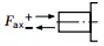
axial force |
±FAch, Max | N | 400 | 700 | 1000 | 1500 | 2000 | 1500 | 3000 | 3000 |
Zulässige Eingangs- und Durchtriebsdrehmomente
| Größe | 10 | 18 | 28 | 45 | 60/63 | 72 | 85 | 100 | |||
| Drehmoment bei VG-Max und Δp = 250 bar1) | MMax | Machs gut | 42 | 71 | 111 | 179 | 250 | 321 | 338 | 398 | |
| Maximales Eingangsdrehmoment an der Antriebswelle2) | |||||||||||
| S | ME max | Machs gut | 126 | 124 | 198 | 319 | 630 | 630 | 1157 | 1157 | |
| ∅ | in | 3/4 | 3/4 | 7/8 | 1 | 1 1/4 | 1 1/4 | 1 1/2 | 1 1/2 | ||
| R | ME max | Machs gut | - | 160 | 250 | 400 | 650 | 650 | 1215 | 1215 | |
| ∅ | in | - | 3/4 | 7/8 | 1 | 1 1/4 | 1 1/4 | 1 1/2 | 1 1/2 | ||
| U | ME max | Machs gut | 60 | 59 | 105 | 188 | 306 | 306 | 628 | 628 | |
| ∅ | in | 5/8 | 5/8 | 3/4 | 7/8 | 1 | 1 | 1 1/4 | 1 1/4 | ||
| W | ME max | Machs gut | - | - | 140 | 220 | 396 | 383 | 650 | 650 | |
| ∅ | in | - | - | 3/4 | 7/8 | 1 | 1 | 1 1/4 | 1 1/4 | ||
| P | ME max | Machs gut | 90 | - | - | - | - | - | - | - | |
| ∅ | mm | 18 | - | - | - | - | - | - | - | ||
| Maximum through-drive torque | |||||||||||
| S | MD max | Machs gut | - | 108 | 160 | 319 | 484 | 484 | 698 | 698 | |
| R | MD max | Machs gut | - | 120 | 176 | 365 | 484 | 484 | 698 | - | |
| U | MD max | Machs gut | - | 59 | 105 | 188 | 306 | 306 | 628 | 628 | |
| W | MD max | Machs gut | - | - | 140 | 220 | 396 | 383 | 650 | 650 | |
Distribution of torques
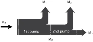
| Torque at 1st pump | M1 |
| Torque at 2nd pump | M2 |
| Torque at 3rd pump | M3 |
| Input torque | ME=M1+M2+M3 |
| ME < ME max | |
| Through∙drive torque | MD=M2+M3 |
| MD < MD max |
1)Efficiency not considered
2) For drive shafts with no radial force
