Wenzhou Prance Hydraulic Equipment Co., Ltd

-1.webp "A10VO63DFR1-53R(01) (1)")
-2.webp "A10VO63DFR1-53R(01) (2)")
-3.webp "A10VO63DFR1-53R(01) (3)")
-4.webp "A10VO63DFR1-53R(01) (4)")
-5.webp "A10VO63DFR1-53R(01) (5)")
-6.webp "A10VO63DFR1-53R(01) (6)")
Custom Hydraulic Variable Displacement Pump A10VO 53 Series
1.Variable pump with axial piston rotary group in swashplate design for hydrostatic drives in open circuit.
2.High permissible drive speed
3.Favorable power-to-weight ratio – compact dimensions
4.Excellent suction characteristics
5.Electro-hydraulic pressure control
6.Power control
Detailed description
This axial piston variable pump adopts a swashplate rotary group structure, professionally designed for open-circuit hydrostatic drive systems and suitable for various industrial hydraulic operation scenarios. It supports a high permissible drive speed, enabling efficient and high-speed operation of the whole equipment to meet high-frequency working demands. Featuring an optimized power-to-weight ratio, the pump boasts compact overall dimensions and lightweight construction, which facilitates flexible installation and equipment integration while saving layout space. It delivers excellent suction performance with low suction resistance and stable oil filling capacity, effectively preventing cavitation and air suction issues to ensure continuous and reliable hydraulic system operation. Equipped with electro-hydraulic pressure control and independent power control functions, the pump can precisely adjust system pressure and output power according to actual load changes, realizing stable operation, reasonable power matching and effective energy consumption reduction.
Selection and RFQ
This product series should be selected against the approved hydraulic circuit. Confirm required flow or displacement, continuous and peak pressure, drive speed, control arrangement, fluid and installation interface before final selection.
Information to include in your RFQ
- Required displacement or flow at operating speed
- Continuous and peak system pressure
- Drive speed, control requirement and circuit type
- Mounting flange, shaft, ports, fluid and filtration requirement
Related resources
Technical data
| Size | NG | 10 | 18 | 28 | 45 | 60 | 63 | 72 | 85 | 100 | ||
| Displacement, geometric, per revolution | Vg max | cm3 | 10.5 | 18 | 28 | 45 | 60 | 63 | 72 | 85 | 100 | |
| Rotational speed
maximum1) |
at Vg max | nnom | rpm | 3600 | 3300 | 3000 | 26004) | 2700 | 2600 | 2600 | 2500 | 2300 |
| at Vg <Vg max 2) | nmax adm. | rpm | 4320 | 3960 | 3600 | 3120 | 3140 | 3140 | 3140 | 3000 | 2500 | |
| Flow | at nnom and Vg max | qv | I/min | 37 | 59 | 84 | 117 | 162 | 163 | 187 | 212 | 230 |
| at nE = 1500 rpm | qvE | I/min | 15 | 27 | 42 | 68 | 90 | 95 | 108 | 128 | 150 | |
| Power | With Nnom, Vg max
and Δp = 250 bar |
P | kW | 16 | 25 | 35 | 49 | 65 | 68 | 77 | 89 | 96 |
| at nE= 1500 rpm | PE | kW | 7 | 11 | 18 | 28 | 37 | 39 | 45 | 53 | 62 | |
| Torque | at Vg max
and Δp = 250 bar |
M | Nm | 42 | 71 | 111 | 179 | 238 | 250 | 286 | 338 | 398 |
| at Vg max
and Δp = 100 bar |
M | Nm | 17 | 29 | 45 | 72 | 95 | 100 | 114 | 135 | 159 | |
| Rotary stiffness Drive shaft | S | c | Nm/rad | 9200 | 11000 | 22300 | 37500 | 65500 | 65500 | 65500 | 143000 | 143000 |
| R | c | Nm/rad | - | 14800 | 26300 | 41000 | 69400 | 69400 | 69400 | 152900 | 152900 | |
| U | c | Nm/rad | 6800 | 8000 | 16700 | 30000 | 49200 | 49200 | 49200 | 102900 | 102900 | |
| W | c | Nm/rad | - | - | 19900 | 34400 | 54000 | 54000 | 54000 | 117900 | 117900 | |
| P | c | Nm/rad | 10700 | - | - | - | - | - | - | - | - | |
| Moment of inertia of the rotary group | JTW | Kgm2 | 0.0006 | 0.0009 | 0.0017 | 0.003 | 0.0056 | 0.0056 | 0.0056 | 0.012 | 0.012 | |
| Maximum angular acceleration3) | α | rad/s2 | 8000 | 6800 | 5500 | 4000 | 3300 | 3300 | 3300 | 2700 | 2700 | |
| Case volume | V | L | 0.2 | 0.25 | 0.3 | 0.5 | 0.8 | 0.8 | 0.8 | 1 | 1 | |
| Weight without through drive (approx.)
Weight with through drive (approx.) |
m | kg | 8 | 11.5 | 15 | 18 | 22 | 22 | 22 | 36 | 36 | |
| - | 13 | 18 | 24 | 28 | 28 | 28 | 45 | 45 | ||||
Determining the operating characteristics
| Flow | qv=(Vg ∙ n ∙ ηv) / 1000 | I/min |
| Torque | M=(Vg ∙ Δp) /(20 ∙ π ∙ ηhm) | Nm |
| Power | P=(2π ∙ M ∙ n)/60000=(qv ∙ Δp)/(600 ∙ ηt) | kW |
Key
Vg Displacement per revolution in [cm3]
Δp Differential pressure [bar]
n Rotational speed [rpm]
ηv Volumetric efficiency
ηhm Hydraulic-mechanical efficiency
ηt Total efficiency (ηt= ηv*ηhm)
1) The values are applicable:
- At an abs. pressure pabs = 1 bar at the suction port S
- for the optimum viscosity range from Vopt = 36 to 16 mm2/s
- with hydraulic fluid on the basis of mineral oils
2)See diagram on page 9 at speed increase up to nmax adm.
3)The data are valid for values between the minimum required and maximum permissible rotational speed. It applies for external stimuli (e.g. diesel engine 2 to 8 times rotary frequency, cardan shaft twice the rotary frequency). The limit value is only valid fora single pump. The load capacity of the connection parts must be considered.
Permissible radial and axial forces on the drive shaft
| Size | NG | 10 | 18 | 28 | 45 | 60/63 | 72 | 85 | 100 | ||
| Maximum radial force at a/2 | 
radial force |
Fq max | N | 250 | 350 | 1200 | 1500 | 1700 | 1500 | 2000 | 2000 |
| Maximum axial force | axial force |
±Fax max | N | 400 | 700 | 1000 | 1500 | 2000 | 1500 | 3000 | 3000 |
Permissible input and through-drive torques
| Size | 10 | 18 | 28 | 45 | 60/63 | 72 | 85 | 100 | |||
| Torque at Vg max and Δp = 250 bar1) | Mmax | Nm | 42 | 71 | 111 | 179 | 250 | 321 | 338 | 398 | |
| Maximum input torque on drive shaft2) | |||||||||||
| S | ME max | Nm | 126 | 124 | 198 | 319 | 630 | 630 | 1157 | 1157 | |
| ∅ | in | 3/4 | 3/4 | 7/8 | 1 | 1 1/4 | 1 1/4 | 1 1/2 | 1 1/2 | ||
| R | ME max | Nm | - | 160 | 250 | 400 | 650 | 650 | 1215 | 1215 | |
| ∅ | in | - | 3/4 | 7/8 | 1 | 1 1/4 | 1 1/4 | 1 1/2 | 1 1/2 | ||
| U | ME max | Nm | 60 | 59 | 105 | 188 | 306 | 306 | 628 | 628 | |
| ∅ | in | 5/8 | 5/8 | 3/4 | 7/8 | 1 | 1 | 1 1/4 | 1 1/4 | ||
| W | ME max | Nm | - | - | 140 | 220 | 396 | 383 | 650 | 650 | |
| ∅ | in | - | - | 3/4 | 7/8 | 1 | 1 | 1 1/4 | 1 1/4 | ||
| P | ME max | Nm | 90 | - | - | - | - | - | - | - | |
| ∅ | mm | 18 | - | - | - | - | - | - | - | ||
| Maximum through-drive torque | |||||||||||
| S | MD max | Nm | - | 108 | 160 | 319 | 484 | 484 | 698 | 698 | |
| R | MD max | Nm | - | 120 | 176 | 365 | 484 | 484 | 698 | - | |
| U | MD max | Nm | - | 59 | 105 | 188 | 306 | 306 | 628 | 628 | |
| W | MD max | Nm | - | - | 140 | 220 | 396 | 383 | 650 | 650 | |
Distribution of torques
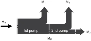
| Torque at 1st pump | M1 |
| Torque at 2nd pump | M2 |
| Torque at 3rd pump | M3 |
| Input torque | ME=M1+M2+M3 |
| ME < ME max | |
| Through∙drive torque | MD=M2+M3 |
| MD < MD max |
1)Efficiency not considered
2) For drive shafts with no radial force
