Wenzhou Prance Hydraulic Equipment Co., Ltd.

Hydraulic Motor Reversing Delay: Valve Response, Compressibility, and Backlash
Hydraulic motor reversing delay is the time between a reverse command and the specified reverse-motion event. It can include controller delay, valve response, pressure redistribution, brake release, shaft deceleration, and mechanical backlash. The correct diagnosis measures those events separately. A motor that pauses before reversing is not automatically worn, and a faster valve setting is not automatically a safe remedy. Define whether the requirement concerns motor shaft motion or movement of the driven machine, then compare synchronized command, pressure and speed observations against the approved circuit and operating limits.
Define the timing requirement before testing
“Reverses slowly” can describe several different events. An operator may mean that a conveyor remains stationary after a button press, that the motor continues in its original direction, or that the shaft reverses while a gearbox output waits before moving. These observations need different evidence. Write down the start event and the finish event used for the timing measurement.
A useful sequence is command accepted, valve actuated, pressure difference changed, shaft stopped, reverse shaft motion established, and driven output moving in reverse. Not every machine provides a sensor for each event. Where an event is inferred, label it as inferred. A controller timestamp does not prove that a spool moved, and a pressure change does not by itself prove that a brake released.
Define any deadband used to identify zero speed and reverse motion. Sensor noise can make a stationary shaft appear to alternate direction. Conversely, a very low-resolution speed signal may report zero during real slow movement. Agree the event definition and measurement uncertainty before comparing machines or declaring that a delay is outside specification.
Separate electrical command from hydraulic response
Check the control sequence first. A programmable controller may intentionally apply a deceleration ramp, a neutral dwell, an interlock, or a brake-release sequence. These functions can protect the machine or coordinate other movements. The delay observed by an operator may therefore begin before any hydraulic reverse command is actually issued.
Record the command signal at an approved point and compare it with the controller’s documented sequence. For proportional control, distinguish the requested command, the actual output and any valve feedback available. Communication updates and logging intervals affect the apparent timing. Two logs with different clocks cannot reliably show which event occurred first unless their timing relationship is established.
A solenoid energizing does not establish the complete hydraulic path. Valve spool type, pilot supply, oil condition and operating pressure can affect the transition. Review the exact valve symbol and code. Do not substitute the response time of a similar catalog valve for a measurement on the installed assembly, and do not bypass an interlock to obtain a shorter reversal time.
Follow both motor ports through the transition
During reversal, the pressure difference producing torque changes while the rotating load still has momentum. The motor can pass through motoring and overrun conditions. A working line may need make-up flow while another line experiences deceleration pressure. The supply-pressure reading alone cannot describe this sequence.
Identify both motor work ports from the approved drawing. The motor direction guide explains why port labels and viewing direction must be defined before a rotation check. For timing work, retain that verified direction convention and add pressure and speed events; do not repeat a trial-and-error hose exchange.
Measurement points should be close enough to answer the diagnostic question and installed with suitable rated equipment. A slow gauge display can conceal a brief pressure excursion. Select instrument bandwidth, range, acquisition rate and synchronization with a qualified engineer. This guide provides no universal pressure ramp, sample rate, or allowable reversal time because the machine duty and component limits determine those values.
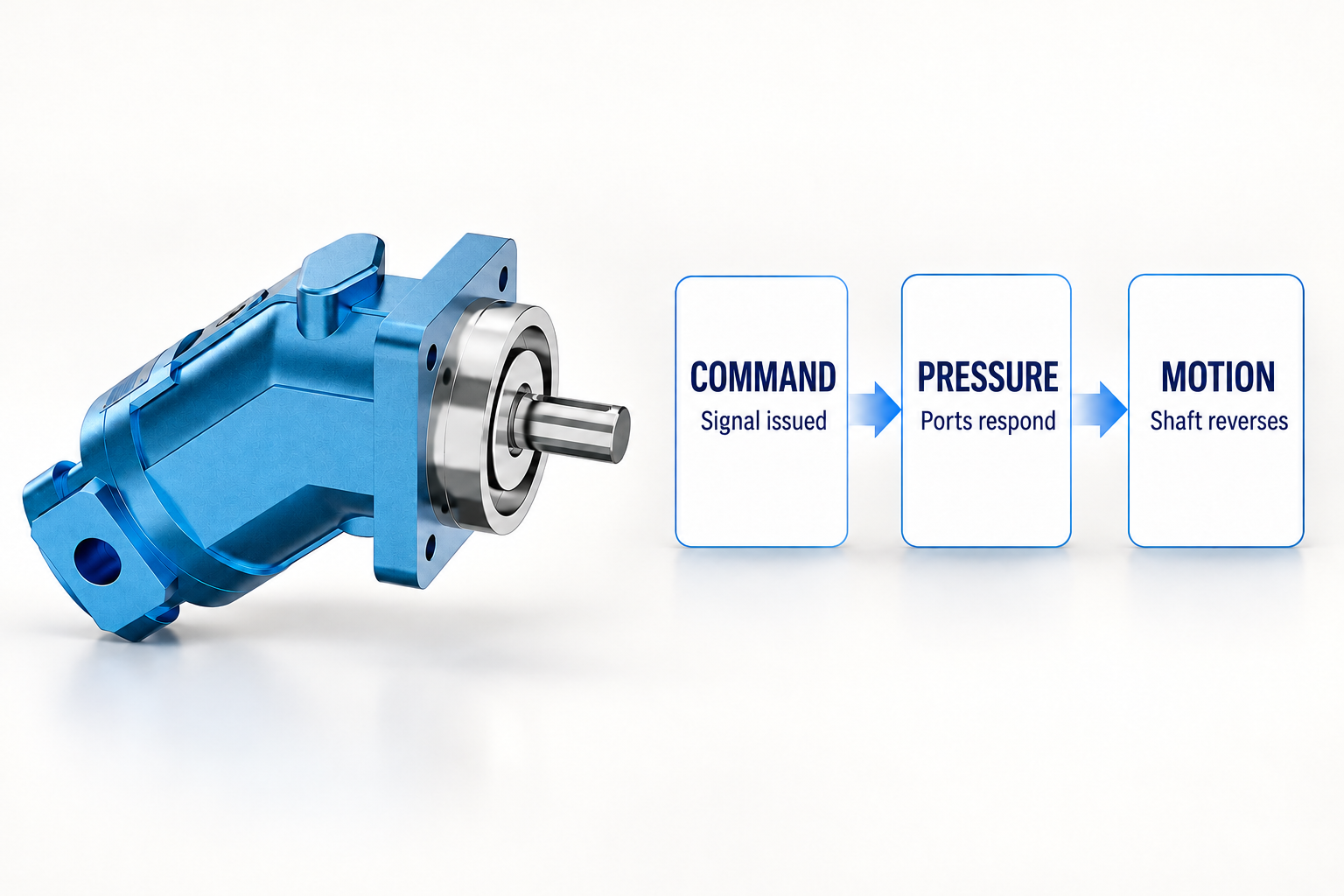
Understand compressibility without blaming every pause on air
Hydraulic oil, hoses and structural compliance allow some volume change as pressure changes. Gas carried in the fluid can further affect stiffness. The circuit volume between the controlling valve and motor therefore matters when a command must establish a new pressure difference before motion changes.
Compressibility is one contributor rather than a complete explanation. A long hose route, an intentional control ramp, a brake, internal leakage and a changing load can overlap. Air in the fluid should be investigated from the circuit, maintenance history and appropriate evidence. A delay alone does not prove aeration, and visible reservoir foam does not quantify the effective stiffness at the motor.
Avoid an unsupported calculation that converts a guessed air percentage into an exact delay. A predictive model needs defensible volumes, pressure states, effective bulk modulus, valve behavior and load dynamics. Use a simplified model to identify what should be measured, then compare it with repeatable observations. Do not use it as permission to increase pressure or remove protective functions.
Distinguish shaft deceleration from mechanical backlash
The shaft must lose its original angular momentum before sustained reverse rotation can occur. Load inertia, resisting torque and hydraulic braking influence that transition. A change in load can alter the time even when the motor and valve are unchanged. Keep the initial speed, load state and temperature comparable when repeating a test.
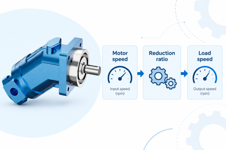
Backlash is different: the motor shaft can already be moving in reverse while clearances in the transmission are taken up before the driven output moves. Measure at both locations if the symptom suggests that distinction. A gearbox, chain drive or coupling can create a visible output pause that should not be assigned entirely to the hydraulic motor.
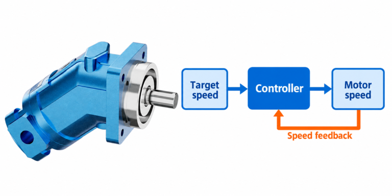
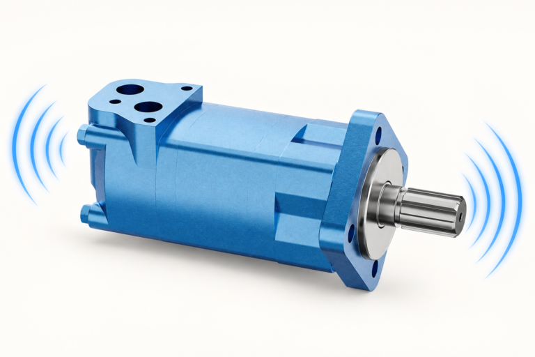
The real product reference here is the A2FM fixed-displacement motor. Its exterior illustrates the motor being discussed; it cannot identify an attached gearbox, brake or valve package that is absent from the photograph. Any external load or coupling requirement comes from the approved assembly documents.
Check brakes and load-control functions as a sequence
If a mechanical brake is fitted, identify its release command, pressure source, required verification and permitted operating sequence. A motor can build pressure while a brake remains engaged. Conversely, releasing a brake before the hydraulic circuit controls the load can create unintended movement. The safe sequence is a design requirement rather than a tuning choice.
A motor-mounted valve block may include load control, relief, replenishment or other functions. Trace the schematic rather than guessing from the block appearance. Settings and pilot references can affect when pressure becomes useful torque. Do not loosen a pilot line or alter a counterbalance setting to see whether the delay disappears.
For suspended, descending or high-inertia loads, review the entire stopping and reversal strategy with the machine designer. A dwell that feels inconvenient may be part of the protection sequence. Changes must preserve load control under normal operation, loss of command and relevant failure conditions. There is no universal instruction to shorten dwell, raise relief pressure or add a check valve.
Build a timing evidence table
Use the same clock and event definitions wherever possible. The table below is a qualitative test-planning aid, not a set of acceptance limits.
| Interval or observation | Nachweis zu sammeln | Possible distinction | Caution |
|---|---|---|---|
| Operator input to reverse output | Input log and actual controller output | Programmed ramp or interlock versus downstream delay | Do not bypass safety logic |
| Valve command to port-pressure change | Approved electrical signal and synchronized port measurements | Valve or pilot response versus load response | Coil current does not prove spool position |
| Pressure change to zero shaft speed | Both work-port pressures and signed shaft speed | Deceleration and load inertia | Check pressure and speed limits throughout |
| Zero speed to reverse shaft motion | Speed event definition and brake evidence if fitted | Breakaway, pressure build-up or brake sequence | Near-zero sensor uncertainty matters |
| Reverse shaft motion to output motion | Motor and driven-output position or speed | Transmission backlash or mechanical compliance | Keep guards and observation clearance |
| Delay changes after warming | Repeatable temperature, fluid and load records | Viscosity-dependent response or leakage contribution | Temperature change alone does not identify wear |
Run a controlled comparison and interpret the result
Start with the documented normal operating condition and a safe test plan. Record the machine identity, motor and valve codes, fluid condition, initial speed, load, command ramp and temperature. Set stop conditions before the test. A pressure excursion, unexpected movement, developing leak or abnormal vibration is a reason to stop rather than repeat the reversal for a better recording.
Change one authorized variable at a time. Comparing a cold unloaded start with a warm fully loaded reversal cannot isolate a valve issue. Retain raw traces and record the reason for each change. If a proposed adjustment improves the measured interval, verify that it has not worsened overshoot, stopping distance, pressure excursions or load control.
Das NIOSH hazardous-energy guidance supports isolation and stored-energy control before instrument installation or mechanical work. Switching off a drive does not establish that hydraulic pressure or load energy has disappeared. Follow the machine procedure, secure movable loads and verify the safe state before opening a connection.
Agree acceptance criteria with the machine requirement
Specify the measured event pair, initial speed, load range, fluid temperature and permitted variation. State whether the requirement concerns shaft reversal, output motion, positioning accuracy or a complete production cycle. A single average reversal time can hide inconsistent behavior or a rare pressure event, so retain the individual results and their operating conditions.
A supplier review should include the schematic revision, motor and valve codes, control settings, brake arrangement where applicable, and synchronized traces. Mark missing information explicitly. The Hydraulikmotor-Palette is a starting point for component discussions, while the radial-piston operating guide offers a comparison of another motor mechanism. Do not transfer response or timing expectations between motor families without evidence.
Häufig gestellte Fragen
Is a reversing pause proof that the motor is worn?
No. Control ramps, valve response, pressure redistribution, brake release, inertia and transmission backlash can contribute. Measure the sequence before identifying a component fault.
Can a faster directional valve remove the whole delay?
Only the valve-related part could potentially change, and the replacement must suit the complete circuit. Mechanical deceleration, brake sequencing and backlash may remain, while a faster transition can create different pressure or motion behavior.
Why does the output wait after the motor shaft reverses?
Transmission backlash or compliance may take up motion before the output changes direction. Compare shaft and driven-output measurements at matched operating conditions to distinguish that interval from hydraulic delay.
Should I remove a neutral dwell to make reversal quicker?
Do not remove a dwell without reviewing its purpose and the machine’s approved control strategy. It may coordinate braking, stopping or another protective sequence. A shorter interval alone does not establish an acceptable modification.
What should a reversal-time acceptance test state?
Define the start and finish events, sensor method, clock synchronization, initial speed, load, temperature, control settings and stop conditions. Retain individual traces and verify pressure, motion and load-control behavior as well as elapsed time.
Produktdaten und entsprechende technische Ressourcen
The Fixed Displacement Motor A2FM catalog exterior is used as the real product reference in these explanatory images. It does not establish the approved service method, optional construction, or operating limits for an individual order. Confirm the complete code and its documentation. Related resources: Konstantmotor A2FM, Hydraulikmotor-Palette, Drehrichtung des Hydraulikmotors: Anschlussstellen am Motor und Rückwärtsgang, Radialkolbenmotor – Funktionsprinzip: Drehmoment bei niedriger Drehzahl.
Sources and limits of this guide
NPTEL supports hydraulic component principles. The FAA handbook supports general hydraulic flow, pressure, fluid and compliance concepts, without supplying industrial settings or timing limits. NIOSH supports hazardous-energy control. Controller tuning, brake sequence and component operating limits require the approved machine and supplier documents.
- NPTEL: Grundlagen der industriellen Ölhydraulik und Pneumatik
- FAA: Aviation Maintenance Technician Handbook, Airframe Volume 2, hydraulic-system principles
- NIOSH: Verletzungen durch gefährliche Energie verhindern
University lesson: operating principles
NPTEL-NOC IITM presents 6.3 – Hydraulic Motors. The lesson supports the motor operating principles relevant to separating pressure development from observed shaft motion used in this discussion; it is not a model-specific performance or installation approval.