Wenzhou Prance Hydraulic Equipment Co., Ltd.

Series Motor Outlet Pressure: Why Torque Differential Is Not a Case Rating
Hydraulic motor series circuit outlet pressure is a separate selection check from the pressure difference that produces torque. The upstream motor’s outlet supplies the downstream motor, so that outlet can remain highly pressurized during normal work. A motor can have an acceptable torque-producing differential while exceeding its permitted outlet, case or shaft-seal condition. Check each limit using the exact motor configuration and both directions of operation. A high main-port rating does not automatically authorize a series connection, and a case drain is not a substitute for an adequate main-port rating.
Follow the pressure through the complete motor chain
In a simple two-motor series circuit, the pump supplies motor A, its outlet supplies motor B, and motor B returns fluid toward the reservoir. The pressure at A’s outlet is approximately B’s inlet pressure plus the pressure loss of the connecting line. It is not automatically tank pressure. If B needs more torque, its required inlet pressure can raise A’s outlet pressure even though A’s own mechanical load has not changed.
Each motor develops torque from the pressure difference across its working ports, subject to mechanical losses and its displacement. The supply must cover both motors’ required pressure differences and the circuit losses. It is incorrect to assign the full supply pressure as the useful differential for each motor. It is equally incorrect to assume that identical motors always share pressure equally: the loads determine their pressure demands.
Start with a circuit diagram showing work ports, case ports, valves and reservoir connections. Mark actual flow direction for the operating state being assessed. A label such as “return” describes a role in the circuit, not a guarantee of low pressure. If reverse operation changes which physical motor is upstream, repeat the assessment with the pressure order reversed.
Keep four different pressure questions separate
The first question is whether each working port can withstand the actual applied pressure. The second is whether the differential pressure is permitted for the speed, displacement and duty. The third is whether the housing and drain arrangement maintain an acceptable case pressure. The fourth is whether the shaft seal is suitable for its actual pressure and speed conditions. These requirements may be expressed differently in different motor documents.
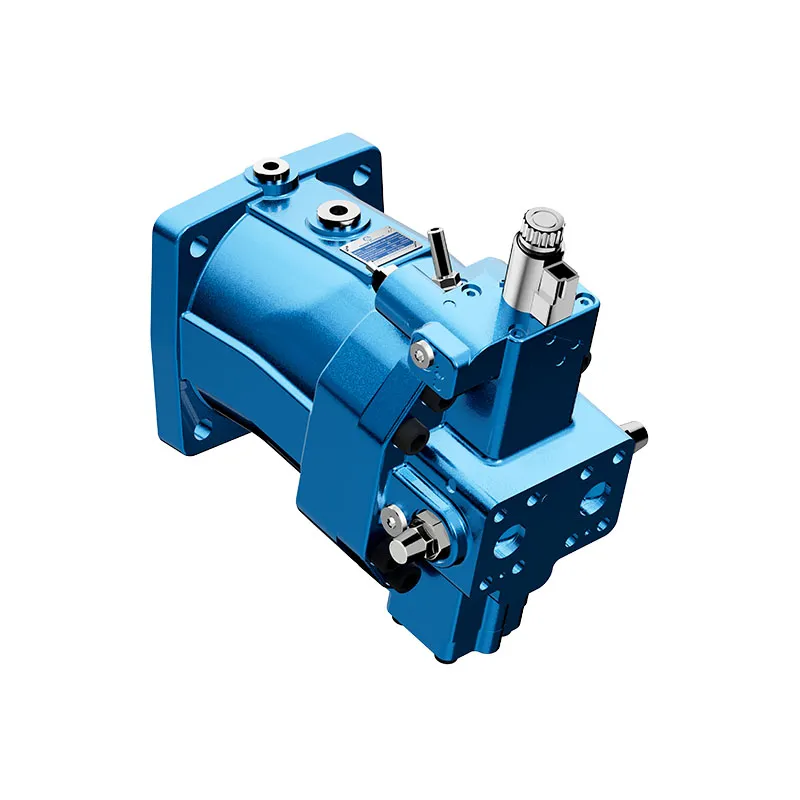
Case pressure depends on the motor’s internal leakage and drainage architecture as well as external plumbing. It cannot safely be assumed equal to outlet pressure in every design. Some internally drained arrangements are affected by pressure at a working port; others use different internal paths. Establish the actual design from the selected configuration rather than inferring it from an unused plug in a photograph.
The International Fluid Power Society training material distinguishes motor work-port conditions from the need to control case and seal pressure. It also illustrates why motor connections must be checked for the specific component. Its example values are not limits for Prance motors. A supplier drawing and the applicable technical data remain necessary before approving the proposed arrangement.
A numerical example of differential and outlet pressure
Assume a steady operating state with 180 bar gauge at motor A’s inlet, 100 bar at A’s outlet, 95 bar at motor B’s inlet and 10 bar at B’s outlet. These are hypothetical instrument readings, not Prance ratings or a recommended circuit. A has 80 bar differential, B has 85 bar differential, and the connecting line accounts for 5 bar. The remaining return-path pressure is also part of the complete supply budget.
For a hypothetical fixed displacement of 100 cm³/rev, ideal torque is T = delta_p V/(2 pi). Converting units gives T_ideal ≈ 0.0159 × delta_p_bar × V_cm³/rev. Motor A’s ideal torque is therefore about 127 N·m, and B’s is about 135 N·m. Real motoring torque is lower because of losses. Starting torque and efficiency need their own applicable performance data.
The calculation says nothing about whether A can tolerate its 100 bar outlet pressure or what pressure exists in its case. Those are separate measurements and specification checks. Even if both differentials were comfortably inside their allowed range, the assembly would still require confirmation of work-port, case and shaft-seal conditions. Do not turn the illustrative readings into an acceptance test limit.
Why a separate case drain may be necessary
An external case drain provides an intended path for internal leakage where the motor design requires it. Its pressure depends on flow, hose and fitting resistance, connection location and the downstream circuit. A line that visually reaches the reservoir can still impose excessive pressure through an unsuitable connector, restriction or shared return arrangement. Confirm pressure at the motor’s approved case measurement point.
Never route a case drain into the inter-motor working line merely because that line is called an outlet. That line may carry the downstream motor’s working pressure. Likewise, do not assume a shared return header is suitable without checking simultaneous flows and transient backpressure. The manufacturer may specify a particular drain arrangement, line routing or permissible pressure behavior.
Not every motor has the same external-drain requirement. Some configurations permit internal drainage under defined conditions; others need an external line. Adding a drain does not automatically make a motor suitable for unlimited outlet pressure, because other internal components and work-port structures still have limits. Review the complete configuration rather than treating one fitting as a universal series-circuit conversion.
Measure the states that load the upstream motor
Select pressure instruments, fittings and sampling equipment suitable for the possible pressures and fluid. Install them with the system isolated, depressurized and secured against unintended motion. Do not loosen a connection to see whether oil escapes, use a hand to find a leak or temporarily obstruct a drain as a diagnostic experiment. Follow the machine’s hazardous-energy procedures throughout the work.
During an authorized test, correlate each motor’s inlet, outlet and case readings with speed, fluid temperature and mechanical load. Include normal startup, changes in load and any permitted reversal. Cold oil can increase drain and return resistance; a warm steady reading may not represent the highest pressure. Suitable transient capture may be required when a slow gauge cannot describe the event.
If the machine includes a brake, counterbalance valve, cross-port relief or anti-cavitation arrangement, include its effects in the review. These components change the pressures during specific operating states. Do not deliberately stall or overrun a drive merely to discover the maximum pressure. Use approved test states and design information, and stop if a documented limit is exceeded or the load cannot be safely controlled.
Compare observations with the right limit
This table is a decision aid based on circuit pressure balance and the distinction between working and case connections. It contains no motor rating. Compare observations with the complete configuration documentation under matching units and duty conditions.
| Beobachtung | Was es bedeutet | Required follow-up |
|---|---|---|
| Upstream outlet pressure rises with downstream load | The downstream demand is reflected upstream | Check upstream outlet rating and case behavior |
| Torque is adequate but the shaft seal leaks | Torque differential does not establish seal suitability | Investigate case pressure, seal condition and configuration |
| Drain pressure rises only when another actuator runs | A shared return may be contributing | Assess simultaneous flow and connection location |
| Pressure is acceptable warm but high at startup | Temperature-dependent resistance may matter | Review cold conditions and transient limits |
| Reversal changes the affected motor | Upstream and downstream roles may have changed | Repeat the pressure map for reverse operation |
| Equal displacement motors run at different speeds | Equal nominal displacement is not exact synchronization | cURL Too many subrequests by single Worker invocation. To configure this limit, refer to https://developers.cloudflare.com/workers/wrangler/configuration/#limits |
cURL Too many subrequests by single Worker invocation. To configure this limit, refer to https://developers.cloudflare.com/workers/wrangler/configuration/#limits.
cURL Too many subrequests by single Worker invocation. To configure this limit, refer to https://developers.cloudflare.com/workers/wrangler/configuration/#limits
cURL Too many subrequests by single Worker invocation. To configure this limit, refer to https://developers.cloudflare.com/workers/wrangler/configuration/#limits.
cURL Too many subrequests by single Worker invocation. To configure this limit, refer to https://developers.cloudflare.com/workers/wrangler/configuration/#limits.
cURL Too many subrequests by single Worker invocation. To configure this limit, refer to https://developers.cloudflare.com/workers/wrangler/configuration/#limits.
cURL Too many subrequests by single Worker invocation. To configure this limit, refer to https://developers.cloudflare.com/workers/wrangler/configuration/#limits
cURL Too many subrequests by single Worker invocation. To configure this limit, refer to https://developers.cloudflare.com/workers/wrangler/configuration/#limits.
Provide the circuit diagram, forward and reverse pressure maps, required torque and speed, displacement condition, temperatures and proposed drain routing. Identify whether values are steady, intermittent or short peaks, and include the duration definitions requested by the supplier. Ask for explicit confirmation of outlet, differential, case and shaft-seal requirements. A replacement chosen only by mounting dimensions and nominal displacement can leave the pressure problem unresolved.
Häufig gestellte Fragen
Does each motor receive half the pump pressure?
Only in a particular operating state where the pressure demands and losses produce that result. Loads determine the required differentials. Equal motor size does not force equal pressure sharing.
Is a high-pressure motor automatically suitable for an upstream position?
No. Check both work ports, the permitted differential, housing pressure, seal conditions and drain arrangement. A headline inlet rating alone is insufficient to approve series operation.
Can I join the case drain to the outlet hose?
Only if the exact motor and circuit documentation explicitly permit that arrangement. An upstream outlet feeds the downstream motor and can be highly pressurized. A required low-pressure drain needs an approved connection.
Will an external drain fix every shaft-seal failure?
No. It may address a pressure-path problem when correctly specified, but the seal, shaft, assembly and other motor limits also need assessment. Determine the actual case pressure and failure evidence before changing plumbing.
Which pressure should be used in the torque calculation?
Use the pressure difference across that motor’s working ports, with consistent units and the correct displacement. Apply appropriate efficiency data for real output. Keep outlet, case and seal acceptance checks separate.
Verwandte Produkt- und Ingenieurressourcen
Hydraulischer Hochdruck-Kolbenmotor A6VM, Hydraulikmotor-Produktpalette, Druck im Hydraulikmotorgehäuse: Grenzen und Vorbeugung von Dichtungsfehlern, Hydraulikmotoren in Reihe oder parallel: Durchfluss, Drehzahl und Lastverteilung. Bestätigen Sie den vollständigen Produktcode und die Anwendungsanforderungen bei der Anforderung einer Konfigurationsüberprüfung.
Technische Referenzen
- International Fluid Power Society study material: component connections, hosted training copy
- OpenStax: fluids, density and pressure
- NIOSH: Preventing Deaths from Uncontrolled Hazardous Energy
Further learning: hydraulic motors
6.3 – Hydraulic Motors by NPTEL-NOC IITM provides background on motor operating principles. Motor operating principles explain differential pressure and shaft output; exact series and drain arrangements still require model-specific verification. It supplements the component fundamentals; it is not a test procedure for the complete circuit discussed above.