Wenzhou Prance Hydraulic Equipment Co., Ltd.

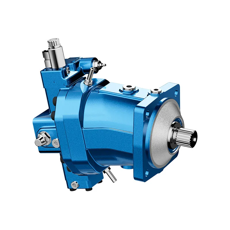
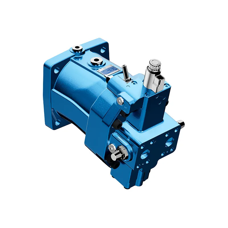
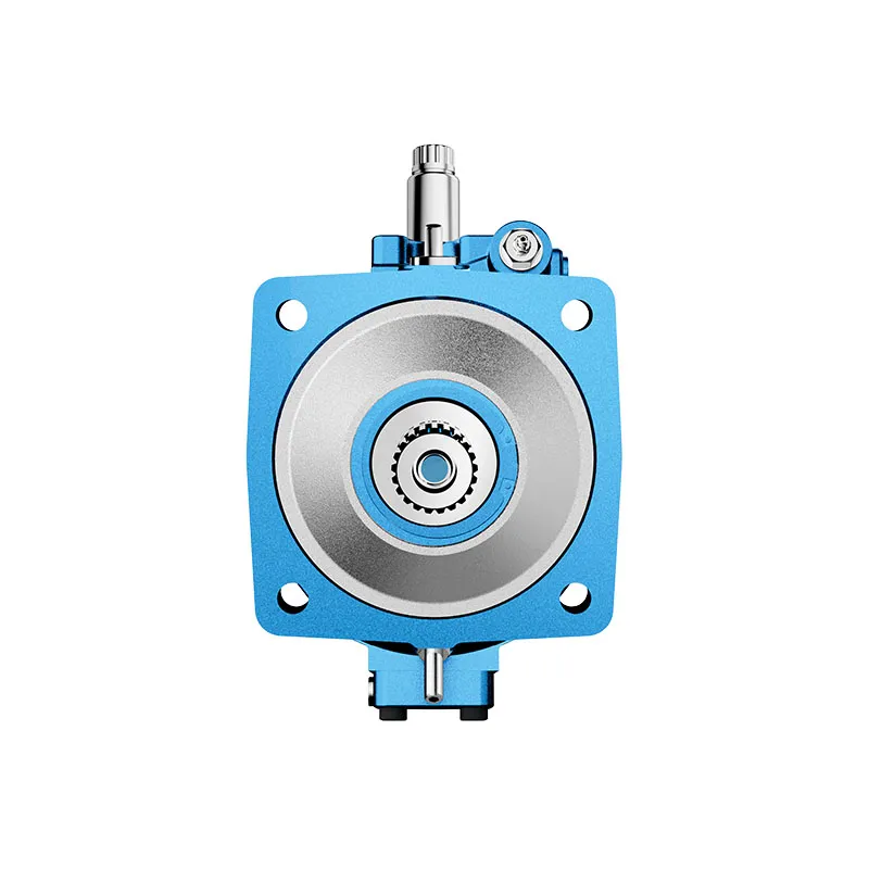
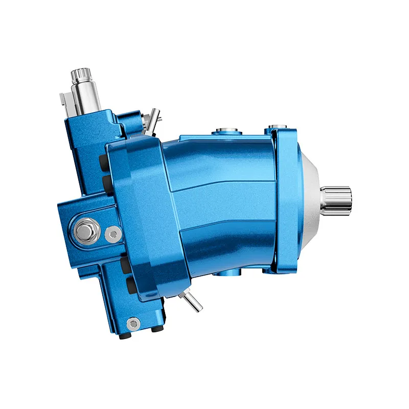
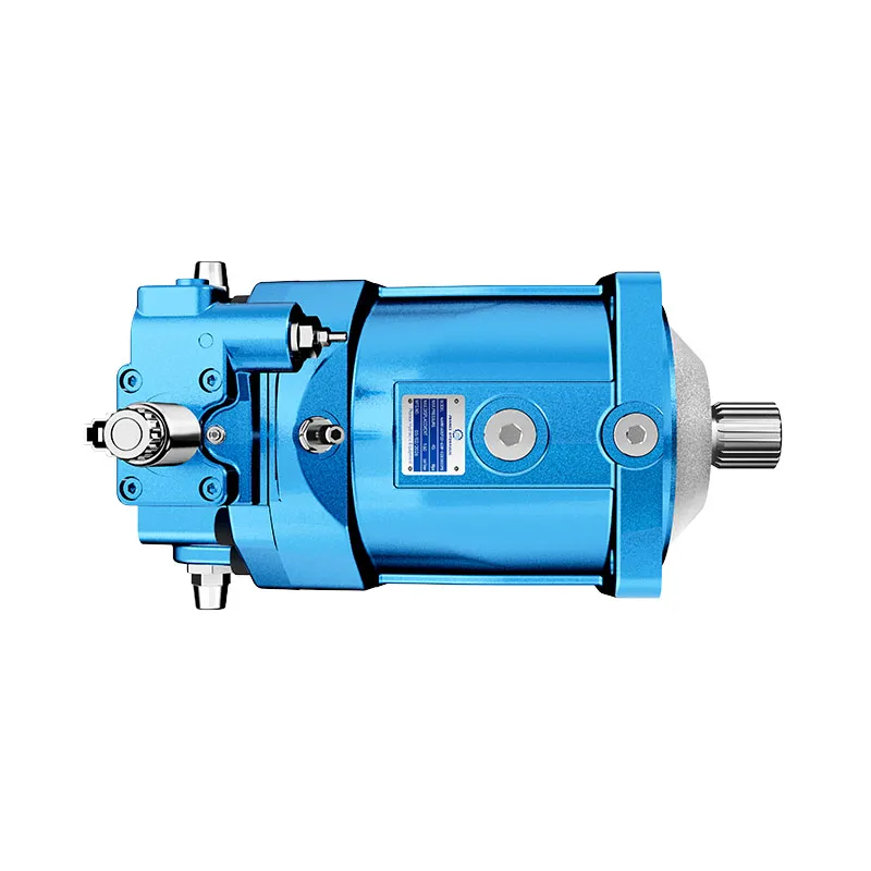
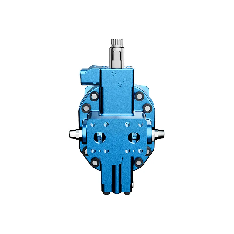
Motor de pistones axiales de alta presión hidráulica A6VM
1.Robust motor with long service life .
2.Approved for very high rotational speeds
3.High control range (can be swiveled to zero)
4.Variety of contra Is Optionally with flushing and boost-pressure valve mounted
5.Optionally with Integrated or mounted counterbalance valve
6.Bent-axis design
Descripción detallada
This equipment is equipped with a robust motor that features a durable structure and high wear resistance, ensuring a long service life even in harsh working environments such as high load, high temperature and frequent start-stop, which reduces maintenance frequency and overall operational costs. The motor is approved for very high rotational speeds, enabling stable and reliable operation at extreme high-speed conditions without excessive vibration, noise or component damage, making it suitable for high-speed hydraulic drive scenarios requiring efficient power output. It has a high control range and can be swiveled to zero displacement, allowing flexible adjustment of output flow from maximum to zero, realizing precise control of the hydraulic system and avoiding energy waste. It offers a variety of control options to adapt to different system requirements, and can be optionally equipped with mounted flushing and boost-pressure valve to enhance oil cleanliness and maintain stable boost pressure. Additionally, it can be optionally configured with an integrated or mounted counterbalance valve to prevent load drift and ensure safe operation. Adopting a bent-axis design, it optimizes power transmission efficiency, reduces internal mechanical wear, and ensures compact structure while enhancing operational stability.
Selección y solicitud de cotización
The A6VM series is used in mobile drive circuits where torque, speed and installation envelope must match the machine layout. Confirm displacement, speed range, case drain routing and mounting interface before ordering.
Información que debe incluir en su RFQ
- Par y velocidad requeridos a la presión de trabajo
- Displacement preference or calculated value
- Brida de montaje, eje y orientación de los puertos
- Application duty cycle and ambient conditions
Recursos relacionados
Escribe código
| 01 | 02 | 03 | 04 | 05 | 06 | 07 | 08 | 09 | 10 | 11 | 12 | 13 | 14 | 15 | 16 | 17 | 18 | 19 | 20 | |||
| A6V | M | / | 63 | W | - | V | - |
Hydraulic fluid
| 01 | Mineral oil and HFD. HFD for sizes 250 to 1000 only in conjunction with long-life bearing "L"(without code) | ||
| HFB, HFC hydraulic fluid | Size 28 to 200 (without code) | ||
| Sizes 250 to 1000(only in conjunction with long-life bearings"L") | E | ||
Unidad de pistones axiales
| 02 | Bent-axis design, variable | A6V |
Drive shaft bearing
| 28...200 | 250 | 355 | 500 | 1000 | |||
| 03 | Standard bearings (without code) | ● | ● | ● | ● | - | |
| Long-life bearings | - | ● | ● | ● | ● | L |
Modo de operación
| 04 | Motor (plug-in motor A6VE, see data sheet 91606) | M |
Tamaño (NG)
| 05 | Geometric displacement | 28 | 55 | 80 | 107 | 140 | 160 | 200 | 250 | 355 | 500 | 1000 |
Dispositivo de control1)
| 06 | Control proporcional, hidráulico | Δpst =10 bar | ● | ● | ● | ● | ● | ● | ● | ● | ● | ● | ● | HD1 | |
| Δpst =25 bar | ● | ● | ● | ● | ● | ● | ● | ● | ● | ● | ● | HD2 | |||
| Δpst =35 bar | - | - | - | - | - | - | - | ● | ● | ● | ● | HD3 | |||
| Control proporcional, eléctrico | U=12V | ● | ● | ● | ● | ● | ● | ● | ● | ● | ● | ● | EP1 | ||
| U=24V | ● | ● | ● | ● | ● | ● | ● | ● | ● | ● | ● | EP2 | |||
| Two-point control, hydraulic | - | - | - | - | - | - | - | ● | ● | ● | ● | HZ | |||
| ● | - | - | - | ● | ● | ● | - | - | - | - | HZ1 | ||||
| - | ● | ● | ● | - | - | - | - | - | - | - | HZ3 | ||||
| Control de dos puntos, eléctrico | U=12V | ● | - | - | - | ● | ● | ● | ● | ● | ● | ● | EZ1 | ||
| U=24V | ● | - | - | - | ● | ● | ● | ● | ● | ● | ● | EZ2 | |||
| U=12V | - | ● | ● | ● | - | - | - | - | - | - | - | EZ3 | |||
| U=24V | - | ● | ● | ● | - | - | - | - | - | - | - | EZ4 | |||
| Automatic control,
relacionado con la alta presión |
With minimum pressure increase
Δp≤approx.10 bar With pressure increase Δp= 100bar |
● | ● | ● | ● | ● | ● | ● | ● | ● | ● | ● | HA1 | ||
| ● | ● | ● | ● | ● | ● | ● | ● | ● | ● | ● | HA2 | ||||
| Control automático, relacionado con la velocidad
pst/pHD=3/100 Hydraulic travel direction valve |
- | - | - | - | - | - | - | ● | ● | ● | ○ | DA | |||
| pst/pHD=5/100 | Hydraulic travel direction valve | ● | ● | ● | ● | ● | ● | ● | - | - | - | - | DA1 | ||
| Electric travel direction valve+
electric Vg madrex circuit |
U=12V | ● | ● | ● | ● | ● | ● | ● | - | - | - | - | DA2 | ||
| U=24V | ● | ● | ● | ● | ● | ● | ● | - | - | - | - | DA3 | |||
| pst/pHD=8/100 | Hydraulic travel direction valve | ● | ● | ● | ● | ● | ● | ● | - | - | - | - | DA4 | ||
| Electric travel direction valve+
electric Vg madrex circuit |
U=12V | ● | ● | ● | ● | ● | ● | ● | - | - | - | - | DA5 | ||
| U=24V | ● | ● | ● | ● | ● | ● | ● | - | - | - | - | DA6 | |||
| 28 | 55 | 80 | 107 | 140 | 160 | 200 | 250 | 355 | 500 | 1000 | ||||
| 07 | Without pressure control/override | ● | ● | ● | ● | ● | ● | ● | ● | ● | ● | ● | ||
| Control de presión | fixed setting | ● | ● | ● | ● | ● | ● | ● | ● | ● | ● | ● | D | |
| Hydraulic override, two-point | ● | ● | ● | ● | ● | ● | ● | 2) | 2) | 2) | 2) | E | ||
| Hydraulic remote control, proportional | - | - | - | - | - | - | - | ● | ● | ● | ● | G | ||
•=Available ○= On request - =Not available
1)Specify response time damping when ordering (sizes 28 to 200)
2) 2nd pressure setting fitted as standard with Version D (sizes 250 to 1000)
Overrides for the HA1 and HA2 controls
| 28 | 55 | 80 | 107 | 140 | 160 | 200 | 250 | 355 | 500 | 1000 | ||||
| 08 | Without override (without code) | ● | ● | ● | ● | ● | ● | ● | ● | ● | ● | ● | ||
| Hydraulic override, remote control, proportional | ● | ● | ● | ● | ● | ● | ● | ● | ● | ● | ● | T | ||
| Remote control electric override, two-point | U=12V | ● | ● | ● | ● | ● | ● | ● | - | - | - | - | U1 | |
| U=24V | ● | ● | ● | ● | ● | ● | ● | - | - | - | - | U2 | ||
| Electric override | U=12V | ● | ● | ● | ● | ● | ● | ● | - | - | - | - | R1 | |
| +travel direction valve, electric | U=24V | ● | ● | ● | ● | ● | ● | ● | - | - | - | - | R2 | |
Series
| 09 | Series 6, index 3 | 63 |
Sentido de giro
| 10 | Viewed on drive shaft, bidirectional | W |
Setting ranges for displacement3)
| 28 | 55 | 80 | 107 | 140 | 160 | 200 | 250 | 355 | 500 | 1000 | |||
| 11 | Vgmin = 0 to 0.7 Vgmax | ● | ● | ● | ● | ● | ● | ● | - | - | - | - | |
| Vgmin =0 to 0.4 Vgmax Vgmax =Vgmax to 0.8 Vgmax | - | - | - | - | - | - | - | ● | ● | ● | ● | 1 | |
| Vgmin > 0.4 Vgmax to 0.8 Vgmax Vgmax =Vgmax to 0.8 Vgmax | - | - | - | - | - | - | - | ● | ● | ● | ● | 2 | |
Material de sellado
| 12 | FKM (fluoroelastómero) | V |
Árbol de transmisión
| 28 | 55 | 80 | 107 | 140 | 160 | 200 | 250 | 355 | 500 | 1000 | |||
| 13 | Splined shaft DIN 5480 | ● | ● | ● | ● | ● | ● | ● | - | - | - | - | A |
| ● | ● | ● | ● | ● | ● | - | ● | ● | ● | ● | Z | ||
| Eje con chaveta paralela DIN 6885 | - | - | - | - | - | - | - | ● | ● | ● | ● | P | |
Brida de montaje
| 28 | 55 | 80 | 107 | 140 | 160 | 200 | 250 | 355 | 500 | 1000 | |||
| 14 | ISO 3019-2 | de 4 agujeros | ● | ● | ● | ● | ● | ● | ● | ● | - | - | - |
| 8-hole | - | - | - | - | - | - | - | - | ● | ● | ● | ||
Port plate for working line4)
| 28 | 55 | 80 | 107 | 140 | 160 | 200 | 250 | 355 | 500 | 1000 | ||||||
| 15 | SAE working ports A and B at rear | 01 | 0 | ● | ● | ● | ● | ● | ● | ● | ● | ● | ● | ● | 010 | |
| 7 | ● | ● | ● | ● | ● | ● | ● | ● | ● | ● | ● | 017 | ||||
| SAE working ports A and B lateral, opposite | 02 | 0 | ● | ● | ● | ● | ● | ● | ● | ● | ● | ● | ● | 020 | ||
| 7 | ● | ● | ● | ● | ● | ● | ● | ● | ● | ● | ● | 027 | ||||
| SAE working ports A and B lateral, opposite + rear | 15 | 0 | - | - | - | - | - | - | - | ● | ● | ● | ● | 150 | ||
| Port plate with 1-stage pressure-relief valves for,mountinga counterbalance valve5) | for BVD20 | 37 | 0 | - | - | - | ● | - | - | - | - | - | - | - | 370 | |
| 8 | - | - | - | ● | - | - | - | - | - | - | - | 378 | ||||
| for BVD20/BVD25 | 38 | 0 | - | ● | ● | ● | ● | ● | ● | ●6) | - | - | - | 380 | ||
| 8 | - | ● | ● | ● | ● | ● | ● | ●6) | - | - | - | 388 | ||||
| for BVE | 38 | 0 | - | - | - | ● | ● | ● | ● | - | - | - | - | 380 | ||
| 8 | - | - | - | ● | ● | ● | ● | - | - | - | - | 388 | ||||
0=Without valve
7=Flushing and boost-pressure valve, mounted
8=Counterbalance valve mounted7)
•=Available ○= On request - =Not available
3)Please specify exact settings for Vgmin and Vgmax in plain text when ordering:Vgmin=...cm3,Vgmax=...cm3
4) Fastening thread,metric
5) Only possible in combination with HD,EP and HA control.
6) Type code for counterbalance valve to be quoted separately in accordance with data sheet 95522- BVD or 95525-BVE.
7) Counterbalance valve MHB32,please contact us.
Speed sensor
| 28 | 55 | 80 | 107 | 140 | 160 | 200 | 250 | 355 | 500 | 10008) | |||
| 16 | Without speed sensor (without code) | ● | ● | ● | ● | ● | ● | ● | ● | ● | ● | ● | O |
| Prepared for HDD speed sensor | ▲ | ▲ | ▲ | ▲ | ▲ | ▲ | ▲ | ● | ● | ● | - | F | |
| HDD speed sensor mounted9) | ▲ | ▲ | ▲ | ▲ | ▲ | ▲ | ▲ | ● | ● | ● | - | H | |
| Prepared for DSM/DSA speed sensor | ● | ● | ● | ● | ● | ● | ● | - | - | - | - | U | |
| DSM/DSA speed sensor mounted9) | ● | ● | ● | ● | ● | ● | ● | - | - | - | - | V | |
Swivel angel sensor
| 28 | 55 | 80 | 107 | 140 | 160 | 200 | 250 | 355 | 500 | 1000 | |||
| 17 | Without swivel angle sensor | ● | ● | ● | ● | ● | ● | ● | ● | ● | ● | - | |
| Optical swivel angle sensor | - | - | - | - | - | - | - | ● | ● | ● | ● | V | |
| Sensor de ángulo de giro eléctrico | - | - | - | - | - | - | - | ● | ● | ● | ● | E | |
Conector para solenoides
| 28 to 200 | 250 to 1000 | |||
| 18 | Without connector (without solenoid, with hydraulic control only)(sizes 250 to 1000) | ● | - | O |
| - | ● | |||
| DEUTSCH molded connector, 2-pin-without suppressor diode | ● | - | P | |
| HIRSCHMANN connector-without suppressor diode | - | ● | ||
Inicio del control
| 28 | 55 | 80 | 107 | 140 | 160 | 200 | 250 | 355 | 500 | 1000 | |||
| 19 | At Vgmin (standard for HA) | ● | ● | ● | ● | ● | ● | ● | ● | ● | ● | ● | A |
| At Vgmax(standard for HD, HZ, EP, EZ, DA) | ● | ● | ● | ● | ● | ● | ● | ● | ● | ● | ● | B | |
Versión estándar/especial
| 20 | Versión estándar | |
| Standard version with installation variants, e.g. T ports open and closed contrary to standard | -Y | |
| Specialversion | -S |
•=Available ○= On request ▲=Not for new projects - =Not available
Aviso
▶In addition to the type code, please specify the relevant technical data when placing your order.
8) Please contact us.
9) Specify type code separately for sensor in accordance with data sheet 95132-DSM or 95133-DSA,95135-HDD and observe the requirements for the electronics.
Datos técnicos
| Tamaño | NG | 28 | 55 | 80 | 107 | 140 | 160 | ||
| Geometric displacement, per revolution1) | Vgmax | cm3 | 28.1 | 54.8 | 80 | 107 | 140 | 160 | |
| Vgmin | cm3 | 0 | 0 | 0 | 0 | 0 | 0 | ||
| Vgx | cm3 | 18 | 35 | 51 | 68 | 88 | 61 | ||
| Velocidad máxima de giro2)(while adhering to the maximum permissible inlet flow) | at Vgmax | nNombre | rpm | 5550 | 4450 | 3900 | 3550 | 3250 | 3100 |
| at Vg<Vgx | nmáx | rpm | 8750 | 7000 | 6150 | 5600 | 5150 | 4900 | |
| where Vgo | nmáx | rpm | 10450 | 8350 | 7350 | 6300 | 5750 | 5500 | |
| Inlet flow3) | at nnom and Vgmax | qvmax | l/min | 156 | 244 | 312 | 380 | 455 | 496 |
| Par de torsión4) | at Vgmax and Δp=400bar | T | Nm | 179 | 349 | 509 | 681 | 891 | 1019 |
| at Vgmax and Δp= 350bar | T | Nm | 157 | 305 | 446 | 596 | 778 | 891 | |
| Rotary stiffness | Vgmax to Vg/2 | cmin | kNm/rad | 6 | 10 | 16 | 21 | 34 | 35 |
| Vg/2 to 0 (interpolated) | cmin | kNm/rad | 18 | 32 | 48 | 65 | 93 | 105 | |
| Momento de inercia para el grupo rotativo | JTW | kgm2 | 0.0014 | 0.0042 | 0.008 | 0.127 | 0.0207 | 0.0253 | |
| Aceleración angular máxima | α | rad/s2 | 47000 | 31500 | 24000 | 19000 | 11000 | 11000 | |
| Volumen de casos | V | l | 0.5 | 0.75 | 1.2 | 1.5 | 1.8 | 2.4 | |
| Weight approx. | m | kg | 16 | 28 | 36 | 46 | 61 | 62 | |
| Tamaño | NG | 200 | 250 | 355 | 500 | 1000 | ||
| Geometric displacement, per revolution1) | Vgmax | cm3 | 200 | 250 | 355 | 500 | 1000 | |
| Vgmin | cm3 | 0 | 0 | 0 | 0 | 0 | ||
| Vgx | cm3 | 76 | 205 | 300 | 417 | 1000 | ||
| Velocidad máxima de giro2)(while adhering to the maximum permissible inlet flow) | at Vgmax | nNombre | rpm | 2900 | 2700 | 2240 | 2000 | 1600 |
| at Vg<Vgx | nmáx | rpm | 4600 | 3300 | 2650 | 2400 | 1600 | |
| where Vgo | nmáx | rpm | 5100 | 3300 | 2650 | 2400 | 1600 | |
| Inlet flow3) | at nnom and Vgmax | qvmax | l/min | 580 | 675 | 795 | 1000 | 1600 |
| Par de torsión4) | at Vgmax and Δp=400bar | T | Nm | 1273 | - | - | - | - |
| at Vgmax and Δp= 350bar | T | Nm | 1114 | 1391 | 1978 | 2785 | 5571 | |
| Rotary stiffness | Vgmax to Vg/2 | cmin | kNm/rad | 44 | 60 | 75 | 115 | 281 |
| Vg/2 to 0 (interpolated) | cmin | kNm/rad | 130 | 181 | 262 | 391 | 820 | |
| Momento de inercia para el grupo rotativo | JTW | kgm2 | 0.0353 | 0.061 | 0.102 | 0.178 | 0.55 | |
| Aceleración angular máxima | α | rad/s2 | 11000 | 10000 | 8300 | 5500 | 4000 | |
| Volumen de casos | V | l | 2.7 | 3.00 | 5.0 | 7.0 | 16.0 | |
| Weight approx. | m | kg | 78 | 100 | 170 | 210 | 430 | |
Rango de velocidad
The minimum rotational speed nmin is not restricted. Please consult us regarding applications requiring uniformity of the rotatory motion at low speeds.
1)The minimum and maximum displacement can be steplessly adjusted,(standard setting for sizes 250 to 1000 if ordering code is missing.Vgmin =0.2×Vgmáx, VG máximo = Vgmadrex)
2) The values are applicable:
-for the optimum viscosity range from Velegir=36 to 16 mm2/s
-with hydraulic fluid based on mineral oils
3)Observe limitation of displacement due to counterbalance valve
4) Torque without radial force, with radial force.
Aviso
▶Valores teóricos, sin eficiencia ni tolerancias; valores redondeados
▶Operation above the maximum values or below the minimum Values may result in a loss of function, a reducd service life or in the destruction of the axial piston unit. Other permissible limit values, such as speed variation, reduced angular acceleration as a function of the frequency and the permissible angular acceleration at start (lower than the maximum angular acceleration) can be found in data sheet 90261.
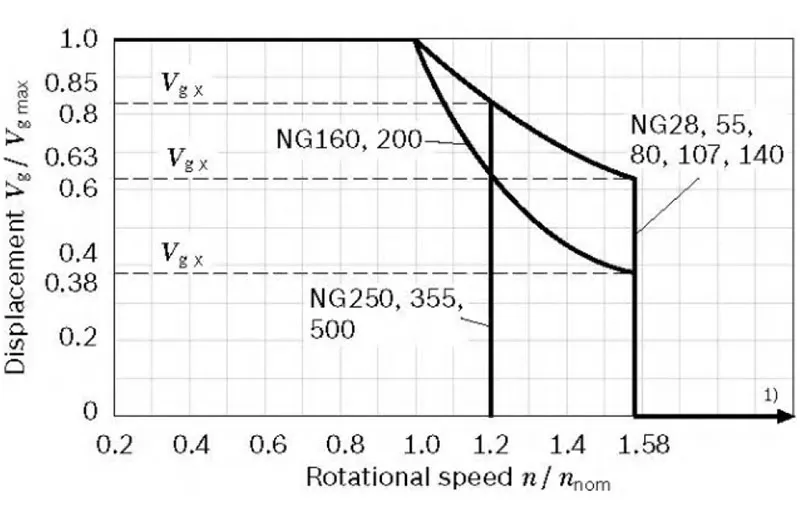
▼Permissible displacement in relation to rotational speed
| Determinación de las características de funcionamiento | ||
| Inlet flow | qv=(Vg×n)/(1000×ηv) | [i/min] |
| Velocidad de giro | n=(qv×1000×ηv)/Vg | [rpm] |
| Par de torsión | T=(Vg×Δp×ηhm)/(20×π) | [Nm] |
| Poder | P=(2π×T×n)/60000=(qv×Δp×ηt)/600 | [kW] |
Clave
Vg=Displacement per revolution [cm3]
Δp=Differential pressure [bar]
n=Rotational speed [rpm]
ηv=Volumetric efficiency
ηhm=Hydraulic-mechanical efficiency
ηt=Total efficiency (nt=nv × nhm)
