Wenzhou Prance Hydraulic Equipment Co., Ltd.

Placas laterales equilibradas en presión en bombas de engranajes: sellado y fricción
Hydraulic gear pump pressure balanced side plates use hydraulic forces to control the lubricating clearance beside the gear faces. Their purpose is to restrict internal leakage while retaining a film that separates moving surfaces. They are not simply covers tightened against the gears, and pressure balancing does not make a pump maintenance-free. The useful question for a buyer or repair engineer is whether the complete plate, seal, bearing and gear arrangement maintains an acceptable balance across the intended operating conditions. A photograph of an assembled pump cannot answer that question. This guide explains the mechanism and the practical decisions it supports without assigning undocumented internal features to a catalog model.
Why the gear faces need a controlled gap
An external gear pump transfers fluid in spaces between the teeth and housing. Near the gear end faces, the interface with a side plate or bearing block also separates regions at different pressures. Oil can pass through that interface instead of reaching the useful outlet. Reducing this bypass can improve delivered flow, but the gears still need to rotate without destructive rubbing.
Consider two otherwise similar operating conditions. At low differential pressure, a generous clearance may not cause an obvious delivery problem. At higher pressure with warm oil, the same pathway can become more consequential. This is why a no-load flow observation is an incomplete assessment of sealing performance. Conversely, a pump that turns freely by hand has not demonstrated adequate lubrication under pressure.
The interface is therefore a controlled leakage and lubrication problem. The objective is not an imaginary absolute seal between rotating metal faces. It is a workable combination of delivery, friction and durability within the pump designer’s operating envelope.
What makes a side plate pressure balanced
A pressure-balanced design applies fluid pressure to selected areas behind the balancing element. Pressure in the thin film on the gear-facing side acts in the opposing direction. The resulting forces, their locations and the element’s freedom to move determine its position. Depending on the construction, the balancing element may be a relatively thin plate or part of a bearing block.
The Purdue research cited below explains this interaction and includes the effects of film lubrication and surface contact. It should not be read as a drawing of every external gear pump. Different machines use different geometries and supporting arrangements. One published reference design cannot establish the pressure, speed or reversibility of a product with a similar exterior.
A useful distinction is between pressure balancing at this internal interface and pressure compensation of pump output. The first concerns end-face sealing forces. The second usually describes a control system that changes displacement or delivery behavior in response to pressure. A fixed-displacement gear pump with balanced plates does not thereby become a variable-displacement pump.
Force balance also requires moment balance
Equal total forces do not necessarily keep a plate parallel to the gears. If the opposing forces act at different locations, the plate can tilt. One edge may approach the gear face while the opposite side opens a larger leakage path. This explains why reviewing only pressure multiplied by one nominal area is insufficient for a complete design.
As an illustrative calculation, 100 bar acting uniformly over 100 square millimeters produces 1,000 newtons. This is a unit-conversion example, not a pump rating or an estimate of the net force on a real plate. Actual film pressure is distributed over a changing interface, and opposing loads must also be included. The location of each contribution matters as much as its magnitude.
The published SAE study specifically examines pressure distribution, clearance height and relative tilt. Its public abstract supports the importance of geometry and operating conditions; it does not provide an approved rebuilding tolerance. Buyers should ask for the applicable drawing and performance evidence rather than converting a research example into a workshop setting.
Leakage and friction pull the design in different directions
If the interface opens too far, more fluid can bypass the useful delivery path. If it closes too far, lubrication may become inadequate and surface contact can increase friction and wear. Neither outcome can be assessed from outlet pressure alone. A pump may reach pressure while delivering too little useful flow or consuming excessive shaft power.
Film behavior also changes with speed, viscosity and pressure. Oil temperature is important because it affects viscosity, but temperature alone is not a substitute for knowing the fluid grade and condition. Two tests performed with different fluids or substantially different temperatures should not be treated as a controlled comparison.
Practical evaluation should connect the hydraulic and mechanical sides: delivered flow, pressure difference, speed, inlet condition and input torque or power. If only pressure is available, state that limitation. Avoid diagnosing a balancing plate from one sound, one temperature reading or a pressure gauge that is upstream of another restriction.
A practical interpretation table
The following is a qualitative engineering review aid. It gives no rejection limits and does not replace the manufacturer’s diagnostic procedure. The balancing and lubrication relationships are supported by the Purdue study and the SAE paper listed in the references.
| Observation under comparable conditions | Interpretación posible | What distinguishes it from an assumption |
|---|---|---|
| Delivery falls as pressure rises | Internal bypass may be increasing | Compare flow at controlled speed, fluid condition and inlet supply |
| Warm operation shows a larger delivery loss | Viscosity-sensitive leakage may contribute | Verify actual oil temperature and grade before comparing tests |
| Input demand rises without a useful delivery increase | Friction or another system loss may be involved | Measure shaft input and pressure losses rather than blaming one component |
| A rebuilt pump shows new rubbing evidence | Geometry, orientation or lubrication may be wrong | Follow an approved inspection process and compare matched parts |
| A replacement plate looks identical | Exterior similarity is inconclusive | Match part numbers, seal layout and the complete pump build |
| A pump passes a no-load check | Basic rotation and delivery may be present | A documented loaded acceptance test is still necessary |
Why seals and orientation belong to the same review
The rear pressure areas must receive the intended pressure. The seals and passages defining those areas are consequently part of the balancing system. Installing an apparently suitable seal in the wrong location can change which area sees high pressure. A plate that can physically be installed both ways is not necessarily functionally reversible.
This does not authorize experimental reassembly. Before opening a pump, isolate the drive, remove stored energy and follow the manufacturer’s service procedure. Preserve identification and orientation information. Do not run a unit assembled from mixed donor parts because the bolt pattern happens to align.
If the original drawing or service information is unavailable, request a complete matched assembly or an approved repair route. A low purchase price for an individual plate is not a meaningful saving if the plate, seals and gears cannot be verified as a compatible set.
What an exterior product photograph can establish
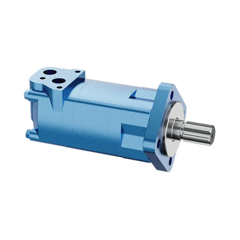
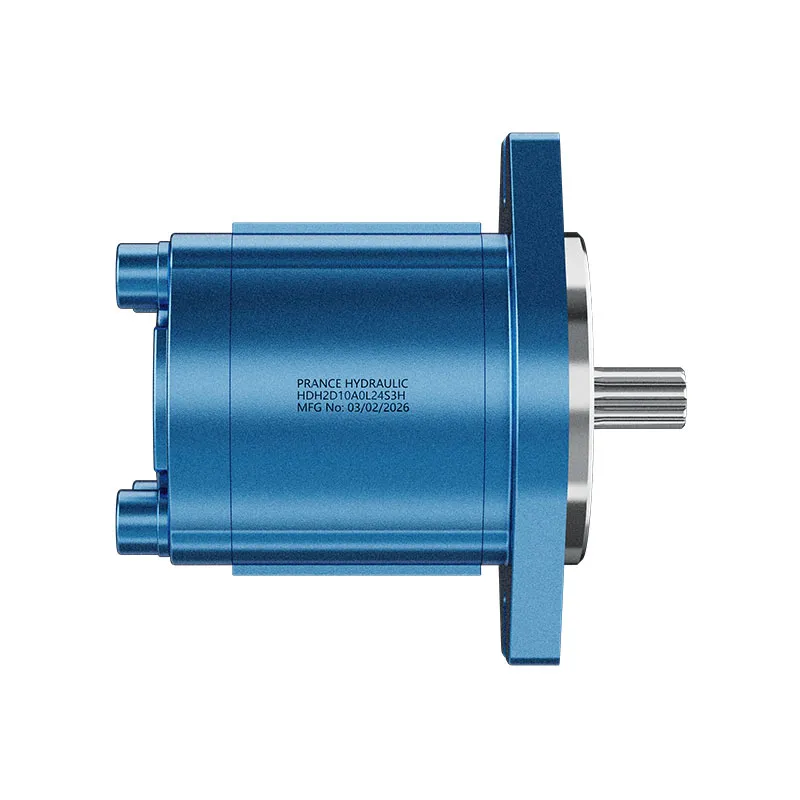
The original HDH gear-pump photographs accompanying this article show a catalog exterior. They help a purchaser identify the housing, mounting arrangement and visible connections to discuss with the supplier. They do not reveal the internal pressure-balance pattern, bearing arrangement or allowable film thickness.
When requesting an HDH configuration, provide the complete identification, rotation, displacement requirement, fluid and intended pressure-speed duty. Ask specifically whether the supplied build uses a pressure-balanced end-face arrangement and request the documentation for that exact build. This avoids turning a general description of gear-pump technology into an unsupported product claim.
For an existing machine, include the original pump code and the hydraulic circuit requirements. A mechanically fitting replacement can still differ in rotation, inlet conditions or duty capability. Do not use the presence of balanced plates as a reason to skip those checks.

How to compare supplier evidence
A useful comparison separates three questions. First, is the internal construction identified for the quoted product? Second, is performance documented under conditions relevant to the application? Third, is the proposed acceptance test repeatable? A statement such as “high efficiency” answers none of these by itself.
Ask whether a performance curve represents the exact displacement and configuration, which fluid and temperature were used, and whether the values are typical or guaranteed. Check whether input power and delivered flow are provided at the same operating point. Comparing a peak efficiency from one test with a nominal flow from another can produce a misleading purchase decision.
For a repair, agree on acceptance criteria before work starts. If the workshop can only confirm assembly and basic operation, record that limited scope. Do not present an unmeasured clearance or an undocumented polishing process as restoration to original performance.
Stop conditions and the next engineering step
Unexpected shaft binding, abnormal heating, metal debris or a sudden change in delivery calls for controlled shutdown and investigation. Continuing to operate at higher pressure to “seat” the parts is not an acceptable substitute for checking assembly and lubrication. Keep personnel away from rotating couplings and pressurized connections during any approved test.
For procurement, the next step is a configuration review supported by a drawing and comparable performance data. For repair, it is a matched-parts and inspection review supported by the relevant service procedure. Both decisions benefit from understanding pressure balance, but neither can be completed by guessing the gap from a generic article.
Preguntas frecuentes
¿Son las placas laterales equilibradas por presión lo mismo que un control de bomba compensado por presión?
No. El equilibrado de las placas laterales se refiere a las fuerzas que actúan en una interfaz interna de lubricación. El control del desplazamiento o del caudal es una función independiente. Confirme la terminología utilizada para la bomba específica.
¿Debe una placa compensada estar en contacto estrecho con la cara del engranaje?
Una interfaz funcional requiere el régimen de lubricación previsto. Un cierre excesivo puede generar fricción y desgaste. La geometría correcta debe basarse en la documentación del diseñador, no en una regla general según la cual cuanto más ajustado, mejor.
Can I reverse a gear pump by turning its side plates around?
No lo des por hecho. Los conductos de presión, las juntas, los rodamientos y la disposición del eje pueden estar diseñados para un sentido de giro específico. Obtén confirmación para el conjunto completo antes de cambiar el sentido de giro o volver a montar las piezas.
Does a warm loss of flow prove side-plate failure?
No. It is one possible sign of internal bypass, but inlet conditions, speed, viscosity and other leakage paths can affect delivery. Controlled measurements are needed to separate these causes.
Can an HDH photograph confirm its balancing design?
No. An exterior photograph supports product identification only. Request the internal construction and operating documentation for the exact quoted code before making a design or repair decision.
Recursos relacionados de productos e ingeniería
Bomba de engranajes externos HDH, gama de productos de bombas hidráulicas, Holgura lateral de la bomba de engranajes hidráulica: Desgaste, fugas y límites de reconstrucción, Pie blando en la bomba–motor: por qué apretar un perno cambia la alineación. Confirmar el código completo del producto y los requisitos de aplicación al solicitar una revisión de configuración.
Referencias técnicas
- Purdue research: balancing elements, lubricating films and surface contact
- SAE research abstract: axial balance of external gear pumps
Aprendizaje adicional: bombas hidráulicas
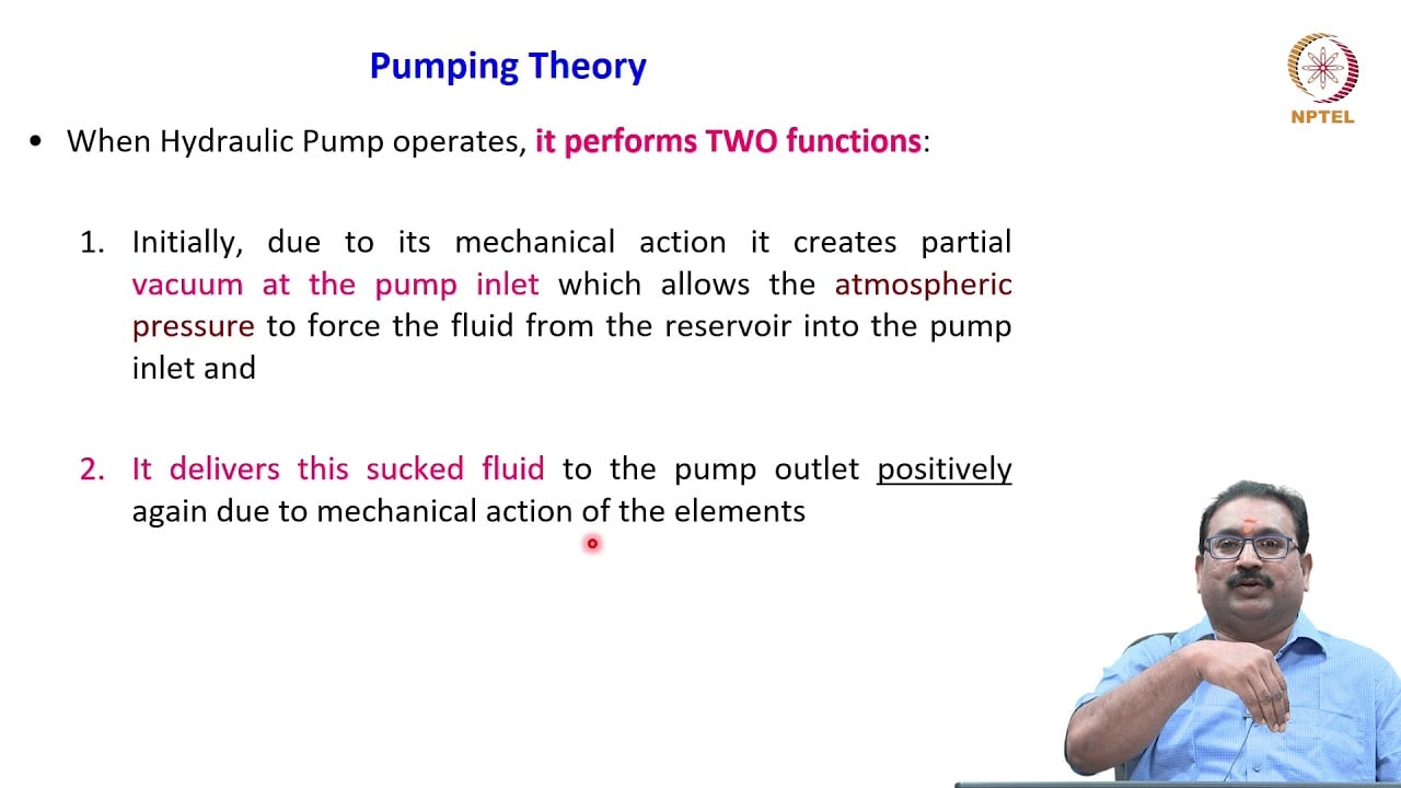
3.2 – Hydraulic Pumps by NPTEL-NOC IITM provides background on pump operating principles. The lecture explains the pumping mechanism and delivery fundamentals; it does not demonstrate the exact internal balancing arrangement or approve this outlet-check circuit. It supplements the component fundamentals; it is not a test procedure for the complete circuit discussed above.