Wenzhou Prance Hydraulic Equipment Co., Ltd.

Válvulas antirretorno de salida de bombas hidráulicas: flujo inverso y aislamiento durante la parada
A hydraulic pump outlet check valve allows delivery toward the system and opposes flow back toward the pump. It can separate a stopped pump from an accumulator or a pressurized common supply, but it is not a substitute for pressure relief, safe isolation or a load-holding design. Its location changes which pipe sections remain pressurized and which pressure a gauge actually measures. Choose the valve by the complete flow path, reverse-pressure duty and allowable loss, then verify the shutdown behavior. Installing a check valve solely because another machine has one can leave a fixed-displacement pump without a safe outlet or trap pressure where maintenance personnel do not expect it.
Start by identifying the source of reverse flow
A stopped pump does not necessarily face a depressurized system. An accumulator, another pump connected to the same header or an externally driven actuator can maintain pressure downstream. If a reverse path exists through the stopped unit, fluid can return toward the pump and potentially drive its shaft. Whether that is permissible depends on the unit and its drive arrangement.
Trace every source on the schematic before choosing a location. A system supplied by one pump without stored energy differs from two pumps feeding a common line. A circuit in which an overrunning motor returns energy also differs from an ordinary supply circuit. The check valve must address a defined reverse-flow path, rather than an unspecified concern about pressure.
NPTEL’s control-valve material explains the one-way function of a check valve. The application review here extends that fundamental function to pump shutdown. It does not assume that every hydraulic circuit needs the same arrangement or that a catalog pump can safely operate as a motor.
Locate the check valve together with the relief path
For a fixed-displacement pump, blocking the delivery path while the drive continues requires a properly designed means of limiting pressure and handling flow. A check valve does not provide that function. The relief or unloading arrangement must protect the pump-side section whenever the check valve is closed and delivery continues.
Consider an outlet check followed by a downstream isolation valve. Closing that isolation valve can remove normal system demand. The fact that a relief valve exists elsewhere on a drawing is insufficient: trace whether pump flow can actually reach it in every relevant valve position. A relief connection isolated by another component cannot protect the separated volume.
This is a schematic design check, not an invitation to close a live valve and see what happens. Any functional test should use an approved procedure, suitable instrumentation and a controlled area. An unexpected pressure rise, noise or heating should trigger the procedure’s stop condition, not a higher relief setting.
Distinguish cracking pressure from running pressure loss
Cracking pressure describes the pressure difference associated with initial opening under stated conditions. Running pressure drop depends on flow and the valve’s characteristics. They are related selection considerations, but a low cracking-pressure label does not prove negligible loss at full pump delivery.
The hydraulic power dissipated across a restriction can be estimated as pressure drop in bar multiplied by flow in liters per minute, divided by 600, giving kilowatts. For example, an assumed 3 bar drop at 40 liters per minute dissipates 0.20 kilowatts. This is a hypothetical steady operating point, not a rating for any valve or HDH pump.
Use the actual fluid, viscosity and flow conditions when evaluating supplier curves. Include cold-start conditions and peak demand, while keeping each comparison within documented limits. A valve chosen only from thread size may fit the line yet impose an unacceptable pressure loss or fail to accommodate the required flow.
Gauge location changes the shutdown diagnosis
A gauge between the pump and check valve measures a different volume from one on the downstream header. After shutdown, the pump-side gauge may fall while the header gauge remains high. That can be consistent with an isolating check valve; it does not by itself prove that the pump suddenly developed a fault.
Conversely, a falling downstream pressure does not uniquely identify check-valve leakage. Directional-valve leakage, accumulator isolation arrangements and other branches can also influence the decay. Compare pressure on both sides using the machine’s designated measurement points and account for what else remains connected.
Do not loosen a fitting to discover which side is pressurized. Instruments must be connected under the site’s isolation and depressurization procedure. A zero indication at one point is not proof that a separate trapped section is empty of stored energy.
Review the whole operating sequence
The qualitative table below combines one-way valve behavior with the distinct pressure-limiting role explained in the cited NPTEL lessons. It is a circuit-review aid, not a universal installation drawing or a set of test limits.
| Circuit state | Pregunta a resolver | Evidence that helps |
|---|---|---|
| Pump starting against a charged line | Can delivery pressure rise safely enough to open the check? | Startup sequence, upstream pressure protection and valve curve |
| Normal delivery | Is the running loss acceptable? | Flow-pressure-drop data at the relevant fluid condition |
| Pump stopped, accumulator charged | Is reverse flow toward the stopped pump blocked as intended? | Schematic, reverse-leakage specification and separate pressure readings |
| Two pumps share a header | Can the operating pump feed the stopped branch? | A traced path through each branch and its check arrangement |
| Downstream line isolated | Can the driven pump still reach pressure protection? | Valve-position review of relief and unloading paths |
| Maintenance begins | Which sections can retain pressure? | Isolation procedure, discharge provisions and verified measurement points |
Accumulators make isolation especially important
An accumulator stores energy independently of continued pump rotation. A check valve can help keep that energy downstream of the pump, but it can also explain why pressure remains after the motor is switched off. Electrical shutdown and hydraulic depressurization are different steps.
For maintenance, use the machine’s documented accumulator isolation and discharge procedure. The NIOSH hazardous-energy alert cited below explains why electrical, mechanical and stored energy must be controlled during servicing. A check valve is one component in that system; it is not a lockable energy-isolating device simply because it resists reverse flow.
If the system must retain accumulator pressure for an intended function, mark and manage that condition explicitly. Do not describe the machine as depressurized merely because the pump-side gauge reads zero. Maintenance access, emergency behavior and subsequent restart all need to account for the retained energy.
Parallel pumps need branch-level thinking
When two pumps supply a common header, stopping one changes the pressure difference across its outlet branch. A branch check may prevent the running pump from supplying the stopped unit. However, there may still be common pilot, drain or auxiliary paths that require separate review.
Do not infer full branch isolation from a single symbol. Confirm which lines join before and after the check, whether each pump has appropriate pressure protection and how the machine starts or stops individual drives. A pressure reading at the header is not a measurement of each pump’s delivered flow.
If one branch repeatedly heats while its drive is stopped, investigate the actual flow path and pressure conditions through an approved diagnostic process. Replacing the pump first can miss a circuit problem. Equally, blaming the check valve without a defined measurement can lead to replacing a functioning component.
Selecting a valve without inventing product capability
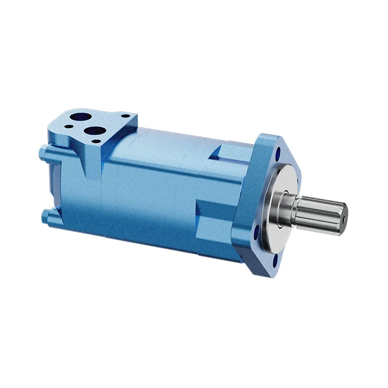
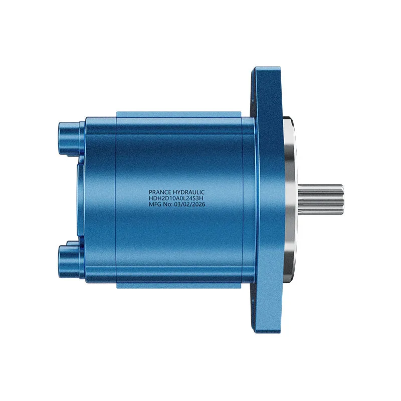
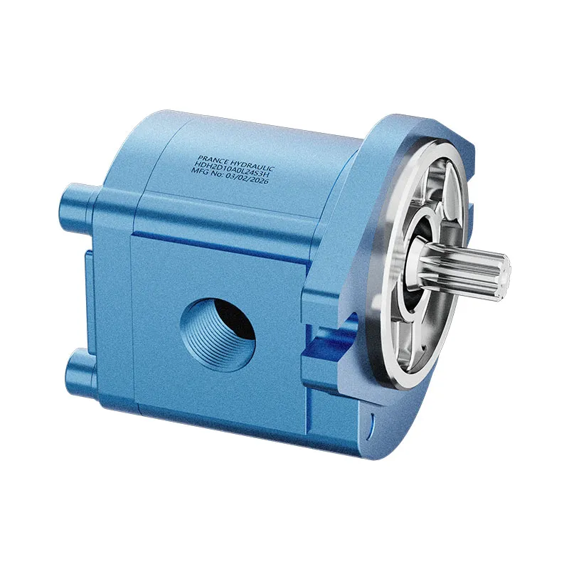
The real pump photographs in this article illustrate the external HDH gear-pump range. They do not establish that the pictured pump contains an outlet check, accepts reverse rotation or is approved for accumulator charging. Those functions require documentation for the complete configuration and application.
For an enquiry, provide the pump identification, normal and maximum delivery, operating fluid, temperature range, reverse pressure, expected shutdown duration and relevant schematic section. Ask for running pressure-drop data, the defined reverse-leakage criterion and connection details. Also identify any pressure that may be trapped between the pump and check valve.
A replacement should match more than the port thread. Flow direction, sealing materials, pressure duty and opening behavior all matter. Where the original component specification is unavailable, request an engineering review instead of selecting a visually similar valve and assuming it is equivalent.
Commissioning should confirm the intended behavior
Agree in advance on what a successful start, run and shutdown look like. Useful observations include the pressure difference across the check during delivery, the separate pressures after shutdown and whether the drive experiences unexpected reverse motion. Instrumentation and permitted actions must come from the approved commissioning procedure.
Record fluid temperature and operating state alongside each observation. A comparison without those conditions can confuse viscosity effects with a change in valve behavior. Do not impose a reverse-flow test on a pump whose documentation does not permit that condition.
The result of commissioning should be a confirmed operating sequence and a clear maintenance isolation boundary. If either remains uncertain, resolve the schematic and component questions before normal operation. The purpose of the outlet check is a defined one-way function within a safe circuit, not simply adding another component to the pressure line.
Preguntas frecuentes
¿Todas las bombas hidráulicas necesitan una válvula antirretorno en la salida?
No. La necesidad depende de las fuentes de flujo inverso, de la bomba y su accionamiento, así como de las funciones del circuito. Evalúe el esquema hidráulico en lugar de copiar la configuración de otra máquina.
¿Una válvula antirretorno protegerá una bomba de engranajes con la descarga bloqueada?
No. It does not provide the pressure-limiting or unloading path needed when a driven fixed-displacement pump cannot deliver to the system. Trace the relief path separately.
Why does pressure remain downstream after the pump stops?
A check valve may isolate an accumulator or another pressurized source. Confirm which volume each gauge measures and follow the documented discharge procedure before maintenance.
Is cracking pressure the same as full-flow pressure drop?
No. Initial opening and running loss describe different conditions. Use the supplier’s flow-pressure-drop curve for the actual operating fluid and demand.
Can an outlet check be used as the maintenance lockout?
Do not treat an ordinary check valve as verified maintenance isolation. Use the machine’s energy-control procedure, control stored pressure and verify the relevant isolated sections before work.
Recursos relacionados de productos e ingeniería
Bomba de engranajes externos HDH, gama de productos de bombas hidráulicas, Cómo preparar una pregunta de aplicación de válvula de retención hidráulica para su revisión, Pie blando en la bomba–motor: por qué apretar un perno cambia la alineación. Confirmar el código completo del producto y los requisitos de aplicación al solicitar una revisión de configuración.
Referencias técnicas
- NPTEL: check valves and cracking pressure
- NPTEL: pressure relief valve function
- NIOSH: uncontrolled hazardous-energy release
Aprendizaje adicional: bombas hidráulicas
5.1 – Directional Control Valves by NPTEL-NOC IITM provides background on one-way check valves and directional control. The lesson introduces check valves and their one-way role, supporting the outlet isolation discussion without approving a particular circuit. It supplements the component fundamentals; it is not a test procedure for the complete circuit discussed above.