Wenzhou Prance Hydraulic Equipment Co., Ltd


cURL Too many subrequests by single Worker invocation. To configure this limit, refer to https://developers.cloudflare.com/workers/wrangler/configuration/#limits
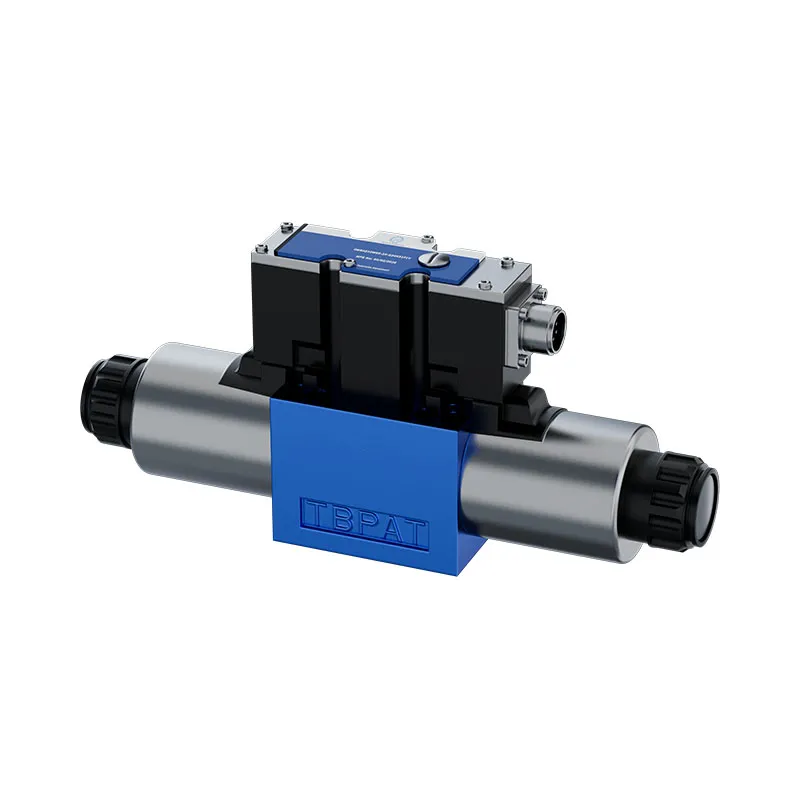
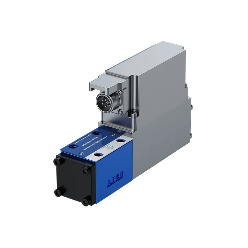
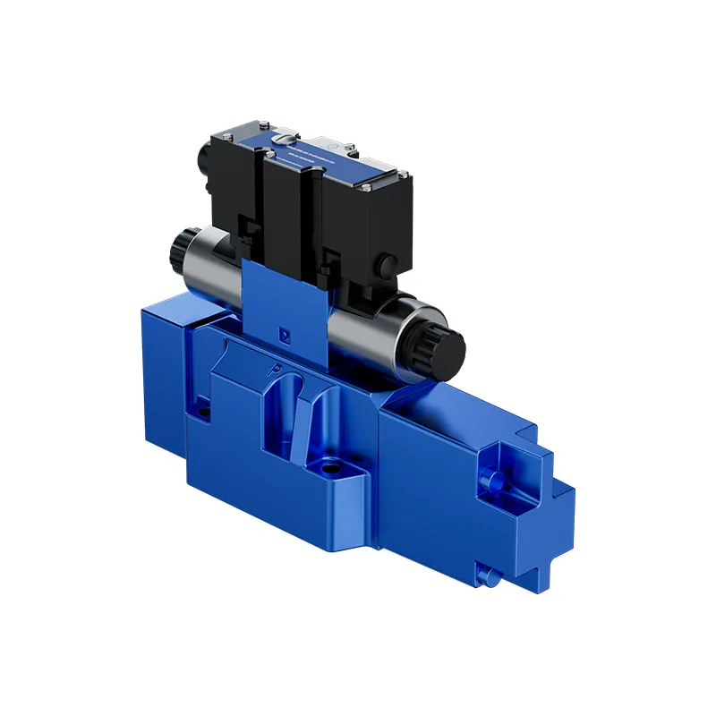
The 4WRLE proportional directional valve uses a pilot-operated arrangement for hydraulic control tasks. Its switched-off spool positions, pilot supply and drain connections must be reviewed together with the electrical command and the machine circuit.
- Pilot-operated proportional control
- Main spool position depends on the ordered version
- Pilot spool and sleeve construction
- Position, velocity or pressure-control applications
PRANCE HYDRAULIC · PRODUCT SERIES
cURL Too many subrequests by single Worker invocation. To configure this limit, refer to https://developers.cloudflare.com/workers/wrangler/configuration/#limits
Pilot-operated proportional directional spool valve · Match pilot supply, drain and spool symbol
The 4WRLE proportional directional valve uses a pilot-operated arrangement for hydraulic control tasks. Its switched-off spool positions, pilot supply and drain connections must be reviewed together with the electrical command and the machine circuit.
Modèle
✓
Demander un devisVoir les données techniques et la fiche technique4WRLEPilot-operated proportional directional spool valve
Confirm the complete model and approved specification with Prance Hydraulic. Product-series references alone do not establish interchangeability.
Étude de configuration · Documentation technique · Sélection de produits
Détails du produit
- Pilot-operated proportional control
- Main spool position depends on the ordered version
- Pilot spool and sleeve construction
- Position, velocity or pressure-control applications
CATÉGORIES : Distributeur hydraulique, Valvule proportionnelle
4WRLE Features & Application
Pilot-operated proportional control
Match the complete control option and its command requirements to the existing controller. Similar housings can use different control arrangements.
Main spool position depends on the ordered version
Specify the full MS order code, installation drawing and operating duty so the quotation can identify the proposed configuration.
Pilot spool and sleeve construction
Account for pilot or replenishment demand and the relevant pressure limits. Include filtration and the return or drain route in the circuit review.
Position, velocity or pressure-control applications
Match the complete control option and its command requirements to the existing controller. Similar housings can use different control arrangements.
4WRLE Specifications
| Series / model | 4WRLE |
|---|---|
| Product type | cURL Too many subrequests by single Worker invocation. To configure this limit, refer to https://developers.cloudflare.com/workers/wrangler/configuration/#limits |
| Conception | Pilot-operated proportional directional spool valve |
| Circuit / selection | Match pilot supply, drain and spool symbol |
| Published nominal sizes | 10, 16, 25, 27 and 35 |
| Pilot arrangement | Confirm internal or external supply and drain from the order code |
4WRLE Selection & Configuration
The 4WRLE proportional directional valve uses a pilot-operated arrangement for hydraulic control tasks. Its switched-off spool positions, pilot supply and drain connections must be reviewed together with the electrical command and the machine circuit.
Define the required neutral or offset state before selecting the spool. A catalog fail-state description is not a guarantee of safe machine behavior. Confirm pilot-pressure limits, drain pressure and the exact electronics or feedback arrangement for the ordered code.

Your Application.
The Right Configuration.
Hydraulic pumps · Hydraulic motors · Hydraulic valves
Send the MS nameplate, operating requirements and installation drawing for a configuration review before quoting.
- Model review — send the full model code or an existing nameplate photograph.
- Interface matching — confirm shaft, mounting flange, rotation and ports.
- Operating conditions — provide flow, pressure, speed, fluid and duty cycle.
- Documentation — request the relevant product data and drawings for your review.

4WRLE Buying Guide
Use this sequence to prepare the 4WRLE configuration for review and quotation.
- Select the circuit symbol and required de-energized spool position.
- State working flow, pressure and the pressure-drop condition for rated flow.
- Review spool overlap and command behavior during startup and switch-off.
- Confirm nominal size, subplate pattern, port and seal requirements.
- Match supply voltage, command input, connector and pin assignment.
- Review pilot supply, drain and feedback where the selected valve uses them.
- Approve the exact valve code, circuit drawing, quantity and documentation.

Selection, Documentation & Project Support

Selection Support
Learn more →Share your hydraulic circuit, operating point and installation requirements for a configuration discussion.
Flow · Pressure · Speed · Interfaces

Technical Resources
Learn more →Review product documentation, model codes and technical data before finalizing the specification.
Datasheets · Model codes · Drawings

cURL Too many subrequests by single Worker invocation. To configure this limit, refer to https://developers.cloudflare.com/workers/wrangler/configuration/#limits
Learn more →cURL Too many subrequests by single Worker invocation. To configure this limit, refer to https://developers.cloudflare.com/workers/wrangler/configuration/#limits.
cURL Too many subrequests by single Worker invocation. To configure this limit, refer to https://developers.cloudflare.com/workers/wrangler/configuration/#limits
Configuration, Quantity & Delivery
Confirm the complete MS code, approved drawing and operating limits. Availability, quantity, documentation and delivery date are confirmed in the quotation.
Discuss Your 4WRLE Application
Send the full model code, operating duty, installation details and quantity.
Request a 4WRLE Quotation4WRLE Questions Before Ordering
What type of product is the 4WRLE?
4WRLE Pilot Operated Proportional Directional Valve. Design: Pilot-operated proportional directional spool valve. Match pilot supply, drain and spool symbol. Confirm the complete order code for the offered version.
Can a similar valve replace the 4WRLE?
cURL Too many subrequests by single Worker invocation. To configure this limit, refer to https://developers.cloudflare.com/workers/wrangler/configuration/#limits.
cURL Too many subrequests by single Worker invocation. To configure this limit, refer to https://developers.cloudflare.com/workers/wrangler/configuration/#limits
Select the circuit symbol and required de-energized spool position. State working flow, pressure and the pressure-drop condition for rated flow. Attach the nameplate, complete order code, installation drawing and required quantity.
4WRLE Technical Data & Documents
View 4WRLE catalog data and operating conditions
cURL Too many subrequests by single Worker invocation. To configure this limit, refer to https://developers.cloudflare.com/workers/wrangler/configuration/#limits.
Données techniques(Pour des applications en dehors de ces valeurs, veuillez nous consulter!)
Général
| Taille | NG | 10 | 16 | 25 | 27 | 35 | |
| Position d'installation | N'importe lequel | ||||||
| Plage de température ambiante | ℃ | -20…+60 | |||||
| Durée maximale de stockage | années | 1 (si les conditions de stockage sont respectées ; se référer aux instructions d'utilisation 07600-B) | |||||
| Sine test according to DIN EN 60068-2-6 | ▶Sans plaque d'amortissement | 10 … 2000 Hz/ maximum of 10 g/10 cycles /3 axes | |||||
| ▶Avec plaque d'amortissement 1) | 10 … 2000 Hz/ maximum of 10 g/10 cycles /3 axes | ||||||
| Noise test according to DIN EN 60068-2-64 | ▶Sans plaque d'amortissement | 20 … 2000 Hz/10 gRMS /30 g de crête /30 min. /3 axes | |||||
| ▶Avec plaque d'amortissement 1) | 20 … 2000 Hz/10 gRMS /30 g de crête /24 h /3 axes | ||||||
| Transport shock according to DIN EN 60068-2-27 | ▶Sans plaque d'amortissement | 15 g / 11 ms /3 chocs /3 axes | |||||
| ▶Avec plaque d'amortissement 1) | 15 g / 11 ms /3 chocs /3 axes | ||||||
| Choc selon DIN EN 60068-2-27 | ▶Avec plaque d'amortissement 1) | 35 g/6 ms /1000 chocs /3 axes | |||||
| Poids | kg | 9 | 12 | 19 | 21 | 80 | |
| Humidité relative maximale (sans condensation) | % | 95 | |||||
| Température maximale de la surface du solénoïde | ℃ | 120 (fonctionnement individuel) | |||||
| Valeur MTTFa selon EN ISO 13849 | années | 75 (pour plus de détails, voir la fiche technique 08012) | |||||
| Conformité | ▶CE according to EMC directive 2014/30/EU, tested according to EN 61000-6-2 and EN 61000-6-3 ▶RoHS directive 2015/65/EU ▶REACH ordinance (EC) no. 1907/2006 | ||||||
Hydraulique
| Taille | NG | 10 | 16 | 25 | 27 | 35 | ||||||
| Maximum operating pressure | ▶Ports A, B, P | |||||||||||
| – External pilot oil supply | bar | 350 | 270 | 350 | ||||||||
| – Internal pilot oil supply | bar | 280 | 270 | 280 | ||||||||
| ▶Port X | bar | 280 | 270 | 280 | ||||||||
| ▶Ports T, Y | bar | 250 | 210 | 250 | ||||||||
| Pression pilote minimale (vanne de commande pilote) | bar | 10 | ||||||||||
| Débit maximum | l/min | 300 | 800 | 1250 | 1850 | 4700 | ||||||
| Débit nominal (Δp = 5 bar/ligne de commande) 2) | l/min | 60/100 | 200/250 | 350/400 | 430/600 | 1000/1200/1500 | ||||||
| Débit d'huile pilote3) | ▶Symbole E, W | l/min | 2.4 | 3.5 | 7.5 | 23 | ||||||
| ▶Symbole V, Q3- | l/min | 4.5 | 11.5 | 22 | 29 | |||||||
| Maximum leakage flow (inlet pressure 100 bar) | ▶Symbol E, E1- – Main valve | l/min | 0.06 | 0.13 | 0.17 | 0.61 | ||||||
| – Main valve + pilot control valve | l/min | 0.14 | 0.28 | 0.42 | 1.01 | |||||||
| ▶Symbol w6-, W8- – Main valve | l/min | 0.12 | 0.26 | 0.35 | 1.23 | |||||||
| – Main valve + pilot control valve | l/min | 0.2 | 0.41 | 0.6 | 1.63 | |||||||
| Maximum zero flow (inlet pressure 100 bar) | ▶Symbol V, V1- – Main valve | l/min | 1.7 | 2.3 | 2.8 | 3.3 | 7.2 | |||||
| – Main valve + pilot control valve | l/min | 1.85 | 2.6 | 3.2 | 3.7 | 7.65 | ||||||
| cURL Too many subrequests by single Worker invocation. To configure this limit, refer to https://developers.cloudflare.com/workers/wrangler/configuration/#limits | l/min | 0.4 | 1.6 | 1.8 | 2.2 | 1.6 | ||||||
| – Main valve + pilot control valve | l/min | 0.55 | 1.9 | 2.2 | 2.6 | 2.05 | ||||||
| Position centrale de décharge de débit Δp = 5 bar/bord de contrôle | A→T | B→T | A→T | B→T | A→T | B→T | A→T | B→T | A→T | B→T | ||
| ▶Symbole W6- | l/min | 2.8 | 2.8 | 4 | 4 | 6 | 6 | 6 | 6 | 25 | 25 | |
| ▶Symbole W8- | l/min | 2.8 | 1.4 | 4 | 2 | 6 | 3 | 6 | 3 | 25 | 12.5 | |
| Volume d'huile pilote | cURL Too many subrequests by single Worker invocation. To configure this limit, refer to https://developers.cloudflare.com/workers/wrangler/configuration/#limits | cm3 | 1.3 | 2.9 | 6.8 | 6.8 | 33..2 | |||||
| Huile hydraulique | Voir tableau | |||||||||||
| Plage de viscosité | ▶Recommandé | mm2/s | cURL Too many subrequests by single Worker invocation. To configure this limit, refer to https://developers.cloudflare.com/workers/wrangler/configuration/#limits | |||||||||
| ▶Maximum | mm2/s | cURL Too many subrequests by single Worker invocation. To configure this limit, refer to https://developers.cloudflare.com/workers/wrangler/configuration/#limits | ||||||||||
| Plage de température du fluide hydraulique (passage fluide) | ℃ | cURL Too many subrequests by single Worker invocation. To configure this limit, refer to https://developers.cloudflare.com/workers/wrangler/configuration/#limits | ||||||||||
| Degré maximal admissible de contamination du fluide hydraulique, classe de propreté selon ISO 4406 (c) | Classe 18/16/134) | |||||||||||
| Huile hydraulique | Classification | Matériaux d'étanchéité appropriés | Normes | Fiche technique | |
| Huiles minérales | HL,HLP | NBR, FKM | DIN 51524 | 90220 | |
| Biodegradable | ▶Insoluble dans l'eau | HETG | FKM | ISO 15380 | 90221 |
| HEES | FKM | ||||
| ▶Soluble dans l'eau | HEPG | FKM | ISO 15380 | ||
| Résistant au feu | ▶Sans eau | HFDU (base glycol) | FKM | ISO 12922 | 90222 |
| HFDU (base ester) | FKM | ||||
| HFDR | FKM | ||||
| ▶Contenant de l'eau | HFC (Fuchs : Hydrotherm 46M, Renosafe 500 ; Petrofer : Ultra Safe 620 ; Houghton : Safe 620 ; Union : Carbide HP5046) | NBR | ISO 12922 | 90223 | |
| cURL Too many subrequests by single Worker invocation. To configure this limit, refer to https://developers.cloudflare.com/workers/wrangler/configuration/#limits. | |||||
Statique/dynamique
| Taille | NG | 10 | 16 | 25 | 27 | 35 | |
| Hystérésis | % | <0,1 | |||||
| Sensibilité de réponse | % | <0,05 | |||||
| Plage d'inversion | % | <0,08 | |||||
| Tolérance de fabrication qVmax | % | ≤10 | |||||
| cURL Too many subrequests by single Worker invocation. To configure this limit, refer to https://developers.cloudflare.com/workers/wrangler/configuration/#limits | ▶Symboles E, E1-, W6-, W8. | ms | 25 | 37 | 36 | 36 | 55 |
| Comportement de coupure (après coupure électrique) | ▶Symboles E, E1-, W6-, W8- | Vanne de commande pilote en position de sécurité, la vanne principale se déplace vers une position centrale à ressort chevauchant | |||||
| ▶Symbole V, V1- | cURL Too many subrequests by single Worker invocation. To configure this limit, refer to https://developers.cloudflare.com/workers/wrangler/configuration/#limits | ||||||
| ▶Symbole Q3 | Pilot control valve in fail-safe position, main valve moves to spring-centered “offset position” (P blocked, A/B to port T open) | ||||||
| Temperature drift (temperature range 20℃ … 80℃) | %/10℃ | Décalage zéro <0,25 | |||||
| Compensation zéro | Ex plant +1% | ||||||
Électronique intégrée, électronique intégrée (OBE) - Interface “ A1 ” et “ F1 ”
| Rapport de cycle de service relatif | % | 100 (fonctionnement continu) | |
| Classe de protection selon EN 60529 | IP 65 avec connecteurs enfichables montés et verrouillés | ||
| Tension d'alimentation | VDC | 24 | |
| ▶Terminal A | VDC | min.19/max.36 | |
| ▶Terminal B | VDC | 0 | |
| Maximum admissible residual ripple | Vpp | 2.5 | |
| Maximum power consumption | VA | 40 | |
| Fuse protection, external | AT | 2,5 (décalage temporel) | |
| Input, version “A1” | Amplificateur différentiel, Ri= 100 kΩ | ||
| ▶Bornes D (UE) | VDC | 0…±10 | |
| ▶Bornes E | VDC | 0 | |
| Input, version “F1” | Charge, Rsh=200Ω | ||
| ▶Bornes D (ID-E) | mA | 4…20 | |
| ▶Bornes E (ID-E) | Rétroaction boucle de courant ID-E | ||
| Tension maximale des entrées différentielles par rapport à 0 V | D→B ; E→B (max. 18 V) | ||
| Test signal, version “A1” | LVDT | ||
| ▶Bornes F (UTest) | V | 0 … ±10 | |
| ▶Bornes C | cURL Too many subrequests by single Worker invocation. To configure this limit, refer to https://developers.cloudflare.com/workers/wrangler/configuration/#limits | ||
| Test signal, version “F1” | LVDT signal 4 .. 20 mA on external load 200 … 500 0 maximum | ||
| ▶Bornes F (IF-C) | mA | 4…20 | |
| ▶Bornes C (IF-C) | Boucle de courant rétroaction IF-C | ||
| Mise à la terre fonctionnelle et blindage | (Installation conforme aux normes EMC) | ||
| Adjustment | Étalonné en usine, voir les courbes caractéristiques de la vanne | ||
Électronique intégrée électrique (OBE) - Interface “ L1 ”
| Rapport de cycle de service relatif | % | 100 (fonctionnement continu) | |
| Classe de protection selon EN 60529 | IP 65 avec connecteurs enfichables montés et verrouillés | ||
| Tension d'alimentation | ▶Amplificateur de vanne | VDC | 24 |
| – Pin 2 | VDC | min.18/max.30 | |
| – Pin 5 | VDC | 0 | |
| ▶Interface IO-Link | VDC | 24 | |
| – Pin 1 | VDC | min.18/max.30 | |
| – Pin 3 | VDC | 0 | |
| Consommation électrique maximale | ▶Amplificateur de vanne | A | 2 |
| ▶Interface IO-Link | mA | 50 | |
| Rugosité résiduelle maximale | Vpp | 1.3 | |
| Consommation électrique maximale | mA | 50 | |
| Temps de cycle de processus minimum | ms | 0.6 | |
| Vitesse de transmission COM3 | kBaud (kbit/s) | 230.4 | |
| Classe de port maître requise | Classe B | ||
| Résolution | ▶Transformateur A/D | bit | 12 (ouverture de vanne à 110%) |
| ▶Transformateur D/A | bit | 12 (ouverture de vanne à 110%) | |
| Mise à la terre fonctionnelle | Fournir via bloc de vanne | ||
| Adjustment | Calibré en usine | ||
| Directive | Spécification de l'interface et du système 10-Link Version 1.1.2 | ||
Électronique de contrôle intégrée électrique (OBE) - Interface “ C6 ”
| Rapport de cycle de service relatif | % | 100 (fonctionnement continu) | |
| Classe de protection selon EN 60529 | IP 65 avec connecteurs enfichables montés et verrouillés | ||
| Tension d'alimentation | VDC | 24 | |
| ▶Terminal A | VDC | min.19/max.36 | |
| ▶Terminal B | VDC | 0 | |
| Maximum admissible residual ripple | Vpp | 2.5 | |
| Maximum power consumption | VA | 40 | |
| Fuse protection, external | AT | 2,5 (décalage temporel) | |
| Entrée | Load, Rsh=200Ω | ||
| ▶Bornes D (ID-E) | mA | 0…±10 | |
| ▶Bornes E (ID-E) | Boucle de courant ID-E feedback | ||
| Signal de test | LVDT signal 4 … 20 mA on external load 200 … 500Ω maximum | ||
| ▶Borne F(IF-B) | mA | 4 … 20 | |
| ▶Borne B(IF-B) | Boucle de courant retour d'information | ||
| Mise à la terre fonctionnelle et blindage | (Installation conforme aux normes EMC) | ||
| Adjustment | Étalonné en usine, voir les courbes caractéristiques de la vanne | ||
Related Selection Resources
Request a 4WRLE Quotation
Tell us your required configuration, quantity and application.
Produits associés
cURL Too many subrequests by single Worker invocation. To configure this limit, refer to https://developers.cloudflare.com/workers/wrangler/configuration/#limits.

Code de commande
| 01 | 02 | 03 | 04 | 05 | 06 | 07 | 08 | 09 | 10 | 11 | 12 | 13 | 14 | 15 | 16 | |||
| 4 | WRL | E | J | - | 4X | / | / | 24 | * |
| 01 | 4 ports principaux | 4 |
| 02 | Vanne de commande directionnelle, pilotée | WRL |
| 03 | Avec électronique intégrée (OBE) | E |
| 04 | Taille 10 | 10 |
| Taille 16 | 16 | |
| Taille 25 | 25 | |
| Taille 27 | 27 | |
| Taille 35 | 35 |
| 05 | Symboles par ex. E, E1-, W6- etc. ; version possible voir page 4 |
Débit nominal (Δp = 5 bar/angle de contrôle)
| 06 | -Taille 10 | |
| 60 l/min (seul symbole E, E1-, W6-, W8-, V, V1-) | 60 | |
| 100 l/min | 100 | |
| -Taille 16 | ||
| 200 l/min (seul symbole W6- et W8-) | 200 | |
| 250 l/min (seul symbole E, E1-, V, V1- et Q3-) | 250 | |
| -Taille 25 | ||
| 350 l/min (seul symbole W6- et W8-) | 350 | |
| 400 l/min (seul symbole E, E1-, V, V1- et Q3-) | 400 | |
| -Taille 27 | ||
| 430 l/min (seul symbole W6- et W8-) | 430 | |
| 600 l/min (seul symbole E, E1-, V, V1- et Q3-) | 600 | |
| -Taille 35 | ||
| 1000 l/min (seul symbole E, E1-, V, V1-) | 1000 | |
| 1200 l/min (seul symbole W6-et W8-) | 1200 | |
| 1500 l/min (seul symbole E, E1-, V, V1- et Q3-) | 1500 | |
Caractéristique de débit
| 07 | Linéaire | L |
| Linéaire avec plage de contrôle fin (disponible pour NG 10, autres tailles sur demande) | P | |
| Progressif avec contrôle fin linéaire (seul symbole Q3-) | M |
| 08 | Saut de chevauchement (point d'ouverture 5% avec vanne couverte; seuls symboles E, E1-, W6-, W8-) | J |
| 09 | Série de composants 40 ... 49 (40 ... 49 : dimensions d'installation et de montage inchangées) | 4X |
Matériau du joint (respecter la compatibilité des joints avec le fluide hydraulique utilisé)
| 10 | Joints en NBR | M |
| Joints FKM | V |
Débit d'huile pilote
| 11 | Alimentation en huile pilote externe, retour en huile pilote externe | XY |
| Alimentation en huile pilote interne, retour en huile pilote externe | PY | |
| Alimentation en huile pilote interne, retour en huile pilote interne | PT | |
| Alimentation en huile pilote externe, retour en huile pilote interne | XT |
| 12 | Sans plaque d'amortissement | sans désignation |
| Avec plaque d'amortissement | D |
| 13 | Tension d'alimentation 24 V | 24 |
Interfaces de l'électronique de commande
| 14 | Valeur de commande entrée ±10 V | A1 |
| Valeur de commande entrée 4 ... 20 mA | F1 | |
| Interface IO-Link | L1 | |
| Valeur de commande ±10 mA, valeur réelle 4 ... 20 mA, décharge (connecteur 6+PE) | C6 |
| 15 | Sans membrane de protection électronique | sans désignation |
| Avec membrane de protection électronique | -967 |
| 16 | Pour plus de détails, voir le texte en clair | * |
Données techniques(Pour des applications en dehors de ces valeurs, veuillez nous consulter!)
Général
| Taille | NG | 10 | 16 | 25 | 27 | 35 | |
| Position d'installation | N'importe lequel | ||||||
| Plage de température ambiante | ℃ | -20...+60 | |||||
| Durée maximale de stockage | années | 1 (si les conditions de stockage sont respectées ; se référer aux instructions d'utilisation 07600-B) | |||||
| Test de sinus selon DIN EN 60068-2-6 |
▶Sans plaque d'amortissement | 10 ... 2000 Hz / maximum 10 g / 10 cycles / 3 axes | |||||
| ▶Avec plaque d'amortissement 1) | 10 ... 2000 Hz / maximum 10 g / 10 cycles / 3 axes | ||||||
| Test de bruit selon DIN EN 60068-2-64 |
▶Sans plaque d'amortissement | 20 ... 2000 Hz / 10 gRMS /30 g de crête /30 min. /3 axes | |||||
| ▶Avec plaque d'amortissement 1) | 20 ... 2000 Hz / 10 gRMS /30 g de crête /24 h /3 axes | ||||||
| Choc de transport selon DIN EN 60068-2-27 |
▶Sans plaque d'amortissement | 15 g / 11 ms /3 chocs /3 axes | |||||
| ▶Avec plaque d'amortissement 1) | 15 g / 11 ms /3 chocs /3 axes | ||||||
| Choc selon DIN EN 60068-2-27 | ▶Avec plaque d'amortissement 1) | 35 g/6 ms /1000 chocs /3 axes | |||||
| Poids | kg | 9 | 12 | 19 | 21 | 80 | |
| Humidité relative maximale (sans condensation) | % | 95 | |||||
| Température maximale de la surface du solénoïde | ℃ | 120 (fonctionnement individuel) | |||||
| Valeur MTTFa selon EN ISO 13849 | années | 75 (pour plus de détails, voir la fiche technique 08012) | |||||
| Conformité | ▶CE selon la directive EMC 2014/30/UE, testé selon EN 61000-6-2 et EN 61000-6-3 ▶Directive RoHS 2015/65/UE ▶Règlement REACH (CE) n° 1907/2006 |
||||||
1)Non recommandé pour les applications avec excitation principalement basse fréquence < 300 Hz
Hydraulique
| Taille | NG | 10 | 16 | 25 | 27 | 35 | ||||||
| Maximum pression de fonctionnement |
▶Ports A, B, P | |||||||||||
| - Approvisionnement en huile pilote externe | bar | 350 | 270 | 350 | ||||||||
| - Approvisionnement en huile pilote interne | bar | 280 | 270 | 280 | ||||||||
| ▶Port X | bar | 280 | 270 | 280 | ||||||||
| ▶Ports T, Y | bar | 250 | 210 | 250 | ||||||||
| Pression pilote minimale (vanne de commande pilote) | bar | 10 | ||||||||||
| Débit maximum | l/min | 300 | 800 | 1250 | 1850 | 4700 | ||||||
| Débit nominal (Δp = 5 bar/ligne de commande) 2) | l/min | 60/100 | 200/250 | 350/400 | 430/600 | 1000/1200/1500 | ||||||
| Débit d'huile pilote3) | ▶Symbole E, W | l/min | 2.4 | 3.5 | 7.5 | 23 | ||||||
| ▶Symbole V, Q3- | l/min | 4.5 | 11.5 | 22 | 29 | |||||||
| Maximum débit de fuite (pression d'admission 100 bar) |
▶Symbole E, E1- - Vanne principale |
l/min | 0.06 | 0.13 | 0.17 | 0.61 | ||||||
| - Vanne principale + vanne de commande pilote | l/min | 0.14 | 0.28 | 0.42 | 1.01 | |||||||
| ▶Symbole w6-, W8- - Vanne principale |
l/min | 0.12 | 0.26 | 0.35 | 1.23 | |||||||
| - Vanne principale + vanne de commande pilote | l/min | 0.2 | 0.41 | 0.6 | 1.63 | |||||||
| Maximum débit zéro (pression d'admission 100 bar) |
▶Symbole V, V1- - Vanne principale |
l/min | 1.7 | 2.3 | 2.8 | 3.3 | 7.2 | |||||
| - Vanne principale + vanne de commande pilote | l/min | 1.85 | 2.6 | 3.2 | 3.7 | 7.65 | ||||||
| ▶Symbole Q3- - Vanne principale |
l/min | 0.4 | 1.6 | 1.8 | 2.2 | 1.6 | ||||||
| - Vanne principale + vanne de commande pilote | l/min | 0.55 | 1.9 | 2.2 | 2.6 | 2.05 | ||||||
| Position centrale de décharge de débit Δp = 5 bar/bord de contrôle | A→T | B→T | A→T | B→T | A→T | B→T | A→T | B→T | A→T | B→T | ||
| ▶Symbole W6- | l/min | 2.8 | 2.8 | 4 | 4 | 6 | 6 | 6 | 6 | 25 | 25 | |
| ▶Symbole W8- | l/min | 2.8 | 1.4 | 4 | 2 | 6 | 3 | 6 | 3 | 25 | 12.5 | |
| Volume d'huile pilote | 0...100% | cm3 | 1.3 | 2.9 | 6.8 | 6.8 | 33..2 | |||||
| Huile hydraulique | Voir tableau | |||||||||||
| Plage de viscosité | ▶Recommandé | mm2/s | 20...100 | |||||||||
| ▶Maximum | mm2/s | 10...800 | ||||||||||
| Plage de température du fluide hydraulique (passage fluide) | ℃ | -20...+70 | ||||||||||
| Degré maximal admissible de contamination du fluide hydraulique, classe de propreté selon ISO 4406 (c) | Classe 18/16/134) | |||||||||||
2)Débit pour Δp déviant (bord de contrôle): qx=qVnom×√(Δpx/5)
3)Au port X et Y avec signal d'entrée progressif de 0 ... 100% (pression pilote 100 bar)
4)Les classes de propreté spécifiées pour les composants doivent être respectées dans les systèmes hydrauliques. Une filtration efficace prévient les défauts et augmente simultanément la durée de vie des composants.
| Huile hydraulique | Classification | Matériaux d'étanchéité appropriés | Normes | Fiche technique | |
| Huiles minérales | HL,HLP | NBR, FKM | DIN 51524 | 90220 | |
| Biodegradable | ▶Insoluble dans l'eau | HETG | FKM | ISO 15380 | 90221 |
| HEES | FKM | ||||
| ▶Soluble dans l'eau | HEPG | FKM | ISO 15380 | ||
| Résistant au feu | ▶Sans eau | HFDU (base glycol) | FKM | ISO 12922 | 90222 |
| HFDU (base ester) | FKM | ||||
| HFDR | FKM | ||||
| ▶Contenant de l'eau | HFC (Fuchs : Hydrotherm 46M, Renosafe 500 ; Petrofer : Ultra Safe 620 ; Houghton : Safe 620 ; Union : Carbide HP5046) | NBR | ISO 12922 | 90223 | |
| Avis importants sur les fluides hydrauliques : ▶Pour plus d'informations et de données sur l'utilisation d'autres fluides hydrauliques, veuillez consulter les fiches techniques ci-dessus ou nous contacter. -Il peut y avoir des limitations concernant les données techniques de la vanne (température, plage de pression, durée de vie, intervalles de maintenance, etc.) ! ▶La température d'allumage du fluide hydraulique utilisé doit être supérieure d'au moins 50 K à la température maximale de surface. ▶Eau contenant des biocides et résistants au feu : Si des composants avec un revêtement galvanique en zinc (par exemple la version "J3" ou "J5") ou des pièces contenant du zinc sont utilisés, de petites quantités de zinc dissous peuvent pénétrer dans le système hydraulique et provoquer un vieillissement accéléré du fluide hydraulique. La formation de savon de zinc peut apparaître comme produit de réaction chimique, ce qui peut obstruer les filtres, les buses et les électrovannes - en particulier en cas de chaleur locale. ▶Eau contenant des agents résistants au feu : -En raison de la tendance accrue à la cavitation avec les fluides hydrauliques HFC, la durée de vie du composant peut être réduite jusqu'à 30 % par rapport à l'utilisation avec de l'huile minérale HLP. Afin de réduire l'effet de cavitation, il est recommandé, si possible spécifique à l'installation, de soutenir la pression de retour dans les ports T à environ 20 % de la différence de pression au niveau du composant. -Selon le fluide hydraulique utilisé, la température maximale ambiante et celle du fluide hydraulique ne doivent pas dépasser 50 °C. Afin de réduire la chaleur transmise au composant, le profil de la valeur de commande doit être ajusté pour les valves proportionnelles et à réponse rapide. |
|||||
Statique/dynamique
| Taille | NG | 10 | 16 | 25 | 27 | 35 | |
| Hystérésis | % | <0,1 | |||||
| Sensibilité de réponse | % | <0,05 | |||||
| Plage d'inversion | % | <0,08 | |||||
| Tolérance de fabrication qVmax | % | ≤10 | |||||
| Temps d'actionnement pour 0 ... 100% à X=210 bar | ▶Symboles E, E1-, W6-, W8. | ms | 25 | 37 | 36 | 36 | 55 |
| Comportement de coupure (après coupure électrique) | ▶Symboles E, E1-, W6-, W8- | Vanne de commande pilote en position de sécurité, la vanne principale se déplace vers une position centrale à ressort chevauchant | |||||
| ▶Symbole V, V1- | Vanne de commande pilote en position de sécurité, la vanne principale se déplace vers une "position décalée" centrée par ressort (approx. 6%, P→B/A→T) | ||||||
| ▶Symbole Q3 | Vanne de commande pilote en position de sécurité, la vanne principale se déplace vers une "position décalée" centrée par ressort (P bloqué, A/B vers le port T ouvert) | ||||||
| Dérive de température (plage de température 20℃ ... 80℃) | %/10℃ | Décalage zéro <0,25 | |||||
| Compensation zéro | Ex plant +1% |
||||||
Électronique intégrée, électronique intégrée (OBE) - Interface “ A1 ” et “ F1 ”
| Rapport de cycle de service relatif | % | 100 (fonctionnement continu) | |
| Classe de protection selon EN 60529 | IP 65 avec connecteurs enfichables montés et verrouillés | ||
| Tension d'alimentation | VDC | 24 | |
| ▶Terminal A | VDC | min.19/max.36 | |
| ▶Terminal B | VDC | 0 | |
| Maximum admissible residual ripple | Vpp | 2.5 | |
| Maximum power consumption | VA | 40 | |
| Fuse protection, external | AT | 2,5 (décalage temporel) | |
| Entrée, version "A1" | Amplificateur différentiel, Ri= 100 kΩ | ||
| ▶Bornes D (UE) | VDC | 0...±10 | |
| ▶Bornes E | VDC | 0 | |
| Entrée, version "F1" | Charge, Rsh=200Ω | ||
| ▶Bornes D (ID-E) | mA | 4...20 | |
| ▶Bornes E (ID-E) | Rétroaction boucle de courant ID-E | ||
| Tension maximale des entrées différentielles par rapport à 0 V | D→B ; E→B (max. 18 V) | ||
| Signal de test, version "A1" | LVDT | ||
| ▶Bornes F (UTest) | V | 0 ... ±10 | |
| ▶Bornes C | cURL Too many subrequests by single Worker invocation. To configure this limit, refer to https://developers.cloudflare.com/workers/wrangler/configuration/#limits | ||
| Signal de test, version "F1" | Signal LVDT 4 .. 20 mA sur charge externe 200 ... 500 0 maximum | ||
| ▶Bornes F (IF-C) | mA | 4...20 | |
| ▶Bornes C (IF-C) | Boucle de courant rétroaction IF-C | ||
| Mise à la terre fonctionnelle et blindage | (Installation conforme aux normes EMC) | ||
| Adjustment | Étalonné en usine, voir les courbes caractéristiques de la vanne | ||
Électronique intégrée électrique (OBE) - Interface “ L1 ”
| Rapport de cycle de service relatif | % | 100 (fonctionnement continu) | |
| Classe de protection selon EN 60529 | IP 65 avec connecteurs enfichables montés et verrouillés | ||
| Tension d'alimentation | ▶Amplificateur de vanne | VDC | 24 |
| - Broche 2 | VDC | min.18/max.30 | |
| - Broche 5 | VDC | 0 | |
| ▶Interface IO-Link | VDC | 24 | |
| - Broche 1 | VDC | min.18/max.30 | |
| - Broche 3 | VDC | 0 | |
| Consommation électrique maximale | ▶Amplificateur de vanne | A | 2 |
| ▶Interface IO-Link | mA | 50 | |
| Rugosité résiduelle maximale | Vpp | 1.3 | |
| Consommation électrique maximale | mA | 50 | |
| Temps de cycle de processus minimum | ms | 0.6 | |
| Vitesse de transmission COM3 | kBaud (kbit/s) | 230.4 | |
| Classe de port maître requise | Classe B | ||
| Résolution | ▶Transformateur A/D | bit | 12 (ouverture de vanne à 110%) |
| ▶Transformateur D/A | bit | 12 (ouverture de vanne à 110%) | |
| Mise à la terre fonctionnelle | Fournir via bloc de vanne | ||
| Adjustment | Calibré en usine | ||
| Directive | Spécification de l'interface et du système 10-Link Version 1.1.2 | ||
Électronique de contrôle intégrée électrique (OBE) - Interface “ C6 ”
| Rapport de cycle de service relatif | % | 100 (fonctionnement continu) | |
| Classe de protection selon EN 60529 | IP 65 avec connecteurs enfichables montés et verrouillés | ||
| Tension d'alimentation | VDC | 24 | |
| ▶Terminal A | VDC | min.19/max.36 | |
| ▶Terminal B | VDC | 0 | |
| Maximum admissible residual ripple | Vpp | 2.5 | |
| Maximum power consumption | VA | 40 | |
| Fuse protection, external | AT | 2,5 (décalage temporel) | |
| Entrée | Load, Rsh=200Ω | ||
| ▶Bornes D (ID-E) | mA | 0...±10 | |
| ▶Bornes E (ID-E) | Boucle de courant ID-E feedback | ||
| Signal de test | Signal LVDT 4 ... 20 mA sur charge externe 200 ... 500Ω maximum | ||
| ▶Borne F(IF-B) | mA | 4 ... 20 | |
| ▶Borne B(IF-B) | Boucle de courant retour d'information | ||
| Mise à la terre fonctionnelle et blindage | (Installation conforme aux normes EMC) | ||
| Adjustment | Étalonné en usine, voir les courbes caractéristiques de la vanne | ||