Wenzhou Prance Hydraulic Equipment Co., Ltd

")
")
")
")
")
")
Fixed Displacement Bent Axis Piston Motor AA2FM
1.Fixed displacement motor A2FM of axial piston , bent axis design,suitable for hydrostatic drives in open and closed circuits.
2.Use in mobile and industrial applications
3.The output speed depends on the flow capacity of the pump and the displacement of the motor
4.The torque increases with the pressure different between the high and low pressure side and with increasing displacement
5.One piece pistons with piston rings
Detailed description
The A2FM is a fixed displacement motor adopting an axial piston and bent axis design, which is specifically engineered to be suitable for hydrostatic drives in both open and closed circuits. This bent axis structure optimizes power transmission efficiency, reduces internal friction and mechanical wear, and ensures stable and reliable operation in different circuit configurations, adapting to the diverse working demands of hydraulic drive systems. The motor is widely applicable to both mobile and industrial applications, including construction machinery, agricultural equipment, industrial hydraulic stations, and other equipment requiring stable hydraulic power output, as it can withstand harsh working environments of mobile equipment and meet the stable operation requirements of industrial systems. Its output speed is closely related to the flow capacity of the matched pump and its own displacement—higher pump flow or smaller motor displacement will lead to higher output speed, allowing flexible adaptation to different operational speed needs. The motor’s torque increases with the pressure difference between the high and low pressure sides, and also rises with increasing displacement, ensuring it can provide sufficient power to drive heavy loads smoothly without stalling. Additionally, it adopts one-piece pistons with piston rings, which enhances sealing performance, reduces internal oil leakage, improves volumetric efficiency, and effectively extends the motor’s service life and overall operational reliability.
Selection and RFQ
This motor series should be selected from the required torque, speed and duty cycle. Confirm displacement, working pressure, case-drain arrangement where applicable, mounting interface and fluid conditions before final selection.
Information to include in your RFQ
- Required torque and speed at working pressure
- Preferred displacement or calculated displacement
- Mounting flange, shaft and port orientation
- Duty cycle, fluid, temperature and operating environment
Related resources
Ordering code for standard program
| AA2F | M | / | 6 | W | - | V | ||||||||||
| 01 | 02 | 03 | 04 | 05 | 06 | 07 | 08 | 09 | 10 | 11 | 12 | 13 | 14 | 15 |
Hydraulic fluid
| 01 | Mineral oil and HFD. HFD for sizes 250 only in combination with long-life bearing "L "(without code) | |||||||
| HFB-,HFC hydraulic fluid |
sizes 10 to 180 (without code) | |||||||
| sizes 250 (only in combination with long-life bearing "L") | E- | |||||||
Axial piston unit
| 02 | Bent axis design, fixed, SAE Version | AA2F |
Drive shaft bearing
| 10 to 180 | 250 | |||
| 03 | Standard bearing (without code) | ● | ● | |
| Long-life bearing | - | ● | L | |
Operation mode
| 04 | Motor (plug-in motor A2FE, see RE 91008) | M |
Size
| 05 | Geometric displacement | ||||||||
| size | 10 | 12 | 16 | 23 | 28 | 32 | 45 | 56 | |
| in3/rev. | 0.63 | 0.73 | 0.98 | 1.40 | 1.71 | 1.95 | 2.78 | 3.42 | |
| size | 63 | 80 | 90 | 107 | 125 | 160 | 180 | 250 | |
| in3/rev. | 3.84 | 4.91 | 5.49 | 6.51 | 7.63 | 9.79 | 10.98 | 15.25 | |
Series
| 06 | 6 | |||
Index
| 07 | sizes 10 to 180 | 1 | |
| size 250 | 0 |
Direction of rotation
| 08 | Viewed on drive shaft, bidirectional | W |
Seals
| 09 | FKM (flour-caoutchouc) | V |
Drive shafts
| 10 | 12 | 16 | 23 | 28 | 32 | 45 | 56 | 63 | 80 | 90 | 107 | 125 | 160 | 180 | 250 | |||
| 10 | Splined shaft SAE J744 (ANSI B92.1a) |
● | ● | ● | ● | ● | ● | ● | ● | ● | - | - | ● | ● | ● | ● | ● | S |
| - | - | - | - | - | - | - | ● | ● | - | - | - | - | - | - | - | T | ||
| - | - | - | - | - | - | - | - | - | ● | ● | ● | ● | - | - | - | U | ||
| - | - | - | - | - | - | - | - | - | ● | ● | - | - | - | - | - | Q | ||
| Parallel keyed shaft DIN 6885 |
● | ● | ● | ● | ● | ● | - | ● | ● | ● | ● | ● | ● | ● | ● | - | B | |
| ● | ● | - | ● | ● | - | ● | ● | - | ● | - | ● | - | ● | - | - | P | ||
| SAE parallel keyed shaft | - | - | - | - | - | - | - | - | - | - | - | - | - | - | - | ● | K | |
Mounting flange
| 10 | 12 | 16 | 23 | 28 | 32 | 45 | 56 | 63 | 80 | 90 | 107 | 125 | 160 | 180 | 250 | ||||
| 11 | SAE J744 | 2-hole | ● | ● | ● | - | - | - | - | - | - | - | - | - | - | - | - | - | C |
| 4-hole | - | - | - | ● | ● | ● | ● | ● | ● | - | - | ● | ● | ● | ● | ● | D | ||
| - | - | - | - | - | - | - | - | - | ● | ● | - | - | - | - | - | DN | |||
•=Available ○=On request -= Not available
Port plates for service lines
| 12 | SAE flange ports A and B at rear1) | 51 | 0 | - | ● | ● | ● | ● | ● | ● | ● | ● | 510 | |
| SAE flange ports A and B at side, opposite1) |
52 | 0 | - | ● | ● | ● | ● | ● | ● | ● | ● | 520 | ||
| 7 | - | ● | ● | ● | ● | ● | ● | ● | ● | 527 | ||||
| Threaded ports A and B at side,opposite1) |
53 | 0 | ● | ● | ● | - | - | - | - | - | - | 530 | ||
| Threaded ports A and B at side and rear1)2) |
54 | 0 | - | ● | ● | - | - | - | - | - | - | 540 | ||
| SAE flange ports A and B at bottom1) |
60 | 0 | - | - | - | - | - | ● | ● | - | - | 600 | ||
| Port plate with 1-level pressure-relief valves for mounting a counterbalance valve 3)5) |
BVD 20 | 17 | 1
8 |
- | - | - | - | - | - | ● | - | - | 171 178 |
|
| 18 | - | - | ● | ● | ● | ● | ● | ● | - | 181 | ||||
| BVD/BVE 25 | 18 | - | - | - | - | - | - | - | - | -4) | 188 | |||
| Port plate with pressure-relief valves5) |
19 | 1 | - | - | ● | ● | ● | ● | ● | ● | - | 191 | ||
| 2 | - | - | ● | ● | ● | ● | ● | ● | - | 192 | ||||
| Valves | |
| Without valve | 0 |
| With pressure-relief valve (without pressure boost facility) | 1 |
| With pressure-relief valve (with pressure boost facility) | 2 |
| With flushing and boost pressure valve, mounted | 7 |
| Counterbalance valve BVD/BVE mounted3)6) | 8 |
| Flushing and boost pressure valve, integrated | 9 |
Speed sensors
| 10 to16 | 23 to32 | 45 | 56 to 90 | 107 to 180 | 250 | |||
| 13 | Without speed sensor(without code) | ● | ● | ● | ● | ● | ● | |
| Prepared for HDD speed sensor | - | ▲ | ▲ | ▲ | ▲ | - | F | |
| HDD speed sensor mounted7) | - | ▲ | ▲ | ▲ | ▲ | - | H | |
| Prepared for DSM/DSA speed sensor | - | ● | ● | ● | ● | - | U | |
| DSM/DSA speed sensor mounted7) | - | ● | ● | ● | ● | - | V | |
Special version
| 14 | Standard version (without code) | |
| Special version for slew drives (standard with port plate 19) | J |
Standard / special version
| 15 | Standard version (without code) | |
| Standard version with installation variants, e. g. T ports against standard open or closed | -Y | |
| Special version | -S |
•=Available ○=On request -=Not available ▲=Not for new projects
1.Fastening threads or threaded ports are SAE (UN/UNF)
2.Threaded ports at the sides (sizes 10 to 63) plugged with threaded plugs
3.Note the restrictions on page 32
4.Please contact us.
5.Fastening threads and threaded ports are metric
6.Specify ordering code of counterbalance valve according to data sheet (BVD-RE 95522,BVE-RE 95525) separately.
7.Specify ordering code of sensor according to data sheet(DSM-RE 95132, DSA-RE 95133, HDD-RE 95135) separately and observe the requirements on the electronics
Technical data
Hydraulic fluid
Before starting project planning, please refer to our data sheets RE 90220 (mineral oil), RE 90221 (environmentally acceptable hydraulic fluids), RE 90222 (HFD hydraulic fluids)and RE 90223 (HFA, HFB, HFC hydraulic fluids) for detailed information regarding the choice of hydraulic fluid and application conditions.
The fixed motor AA2FM is not suitable for operation with HFA hydraulic fluid. If HFB, HFC or HFD or environmentally acceptable hydraulic fluids are used, the limitations regarding technical data or other seals must be observed.
Selection diagram
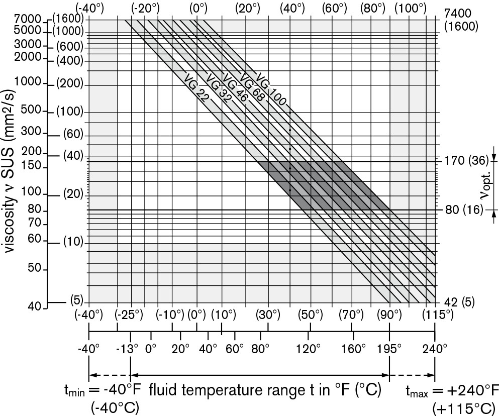
Viscosity and temperature of hydraulic fluid
| Viscosity [SUS (mm2/s)] |
Temperature | Comment | |
| Transport and storage at ambient temperature |
Tmin ≥ -58℉ (-50 ℃) | factory preservation: up to 12 months with standard, up to 24 months with long-term |
|
| Topt = +41 ℉ to +68℉ (+5℃ to + 20℃) |
|||
| (Cold) start-up1) | Vmax=7400(1600) | Tst≥ -40℉(-40℃) | t ≤ 3 min, without load (p ≤ 725 psi (50 bar)), |
| n ≤ 1000 rpm (for sizes 10 to 180), | |||
| n ≤ 0.25 · nnom (for sizes 250) | |||
| Permissible temperature difference | ΔT ≤ 45 ℉(25℃ ) | between axial piston unit and hydraulic fluid | |
| Warm-up phase | ν<7400 to 1850 (1600 to 400) |
T= -40℉ to -13℉ (-40℃ to -25℃) |
at p≤ 0.7·Pnom, n ≤0.5·nnom and t ≤ 15 min |
| Operating phase | |||
| Temperature difference | ΔT = approx. 22 ℉ (12 ℃) | between hydraulic fluid in the bearing and at port T. | |
| Maximum temperature | +240℉ (115℃) | in the bearing | |
| +217 ℉ (103℃) | measured at port T | ||
| Continuous operation | v=1850 to 47 | T=-13℉ to +195℉ | measured at port T, |
| (400 to 10) | (-25℃ to +90℃) | no restriction within the permissible data | |
| Vopt = 170 to 74 (36 to 16) |
|||
| Short-term operation2) | Vmin≥32 (7) | Tmax= +217℉(+103℃) | measured at port T, t < 3 min, p<0.3·Pnom |
| FKM shaft seal1) | T≤ +240℉ (+115℃) | see page 5 | |
| 1) At temperatures below -13℉ (-25 ℃), an NBR shaft seal is required (permissible temperature range:-40℉ to +195℉ (-40℃ to +90 ℃)). |
|||
| 2) Sizes 250, please contact us. | |||
Details regarding the choice of hydraulic fluid
The correct choice of hydraulic fluid requires knowledge of the operating temperature in relation to the ambient temperature: in a closed circuit, the circuit temperature, in an open circuit, the reservoir temperature.
The hydraulic fluid should be chosen so that the operating viscosity in the operating temperature range is within the optimum range (νopt see shaded area of the selection diagram).We recommended that the higher viscosity class be selected in each case.
Example: At an ambient temperature of X℉ (X℃), an opera-ting temperature of 140℉(60℃) is set in the circuit. In the optimum operating viscosity range (νopt, shaded area), this corresponds to the viscosity classes VG 46 or VG 68; to be selected: VG 68.
Note
The case drain temperature, which is affected by pressure and speed, can be higher than the circuit temperature or reservoir temperature. At no point of the component may the temperature be higher than 240℉ (115℃). The temperature difference specified below is to be taken into account when determining the viscosity in the bearing.
If the above conditions cannot be maintained due to extreme operating parameters, we recommend flushing the case at port U (size 250) or using a flushing and boost pressure valve
Filtration of the hydraulic fluid
Finer filtration improves the cleanliness level of the hydraulic fluid, which increases the service life of the axial piston unit.
To ensure the functional reliability of the axial piston unit, a gravimetric analysis of the hydraulic fluid is necessary to determine the amount of solid contaminant and to determine the cleanliness level according to ISO 4406. A cleanliness level of at least 20/18/15 is to be maintained.
At very high hydraulic fluid temperatures (+195℉ to +240℉ (90℃ to maximum 115℃)), a cleanliness level of at least19/17/14 according to ISO 4406 is necessary.
If the above classes cannot be achieved, please contact us.
Shaft seal
Permissible pressure loading
The service life of the shaft seal is influenced by the speed of the axial piston unit and the case drain pressure (case pressure). The mean differential pressure of 30 psi (2 bar) between the case and the ambient pressure may not be enduringly exceeded at normal operating temperature. For a higher differential pressure at reduced speed, see diagram. Momentary pressure spikes (t <0.1 s) of up to 145 psi (10 bar) are permitted. The service life of the shaft seal decreases with an increase in the frequency of pressure spikes.
The case pressure must be equal to or higher than the ambient pressure.

The values are valid for an ambient pressure
Pabs = 15 psi (1 bar).
Temperature range
The FKM shaft seal may be used for case drain temperaturesfrom-13℉ to +240℉ (-25℃ to +115℃).
Note
For application cases below -13℉ (-25℃), an NBR shaft seal is required (permissible temperature range: -40℉ to 195℉(-40℃ to +90℃). State NBR shaft seal in plain text when ordering.
Please contact us.
Direction of flow
| Direction of rotation, viewed on drive shaft | |
| clockwise | counter-clockwise |
| A to B | B to A |
Speed range
No limit to minimum speed nmin. If uniformity of motion is required, speed nmin must not be less than 50 rpm. See table of values on page 7 for maximum speed.
Long-life bearing
Size 250
For long service life and use with HF hydraulic fluids. Identical external dimensions as motor with standard bearings. Subsequent conversion to long-life bearings is possible. Bearing and case flushing via port U is recommended.
Flushing flow (recommended)
| Size | 250 | |
| qv flush | gpm | 2.6 |
| L/min | 10 |
Operating pressure range
(operating with mineral oil)
Pressure at service line port A or B
Sizes 10 to 180
Nominal pressure pnom______________5800 psi (400 bar) absolute
Maximum pressure pmax______________6500 psi (450 bar) absolute
Single operating period__________________10s
Total operating period___________________300h
Summation pressure (pressure A + pressure B)pSu_____________10150 psi (700 bar)
Sizes 250
Nominal pressure pnom____________5100 psi (350 bar) absolute
Maximum pressure pmax____________5800 psi (400 bar) absolute
Single operating period__________________10s
Total operating period__________________300h
Summation pressure (pressure A + pressure B) psu___________10150 psi (700 bar)
Minimum pressure (high-pressure side)___________________365 psi (25 bar) absolute
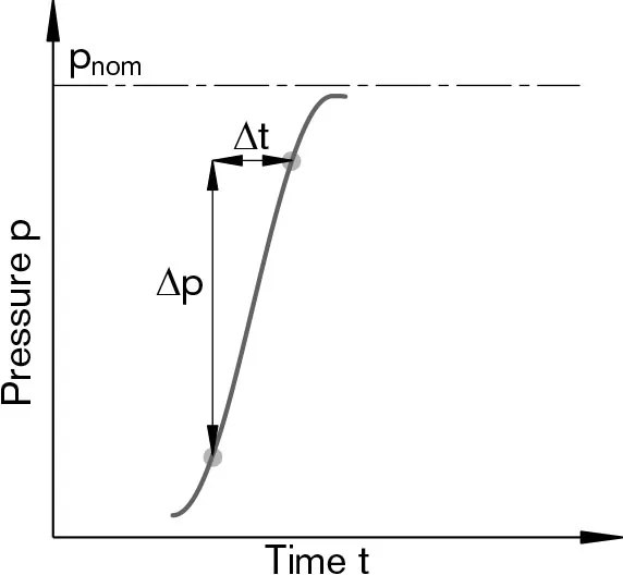
Rate of pressure change RA max
with integrated pressure-relief valve___________130000 psi/s (9000 bar/s)
without pressure-relief valve______________232000 psi/s (16000 bar/s)
Note
Values for other hydraulic fluids, please contact us.
Minimum pressure - pump mode (inlet)
To prevent damage to the axial piston motor in pump operating mode (change of high-pressure side with unchanged direction of rotation, e.g. when braking), a minimum pressure must be guaranteed at the service line port (inlet). The minimum pressure depends on the speed of the axial piston unit (see characteristic curve below).
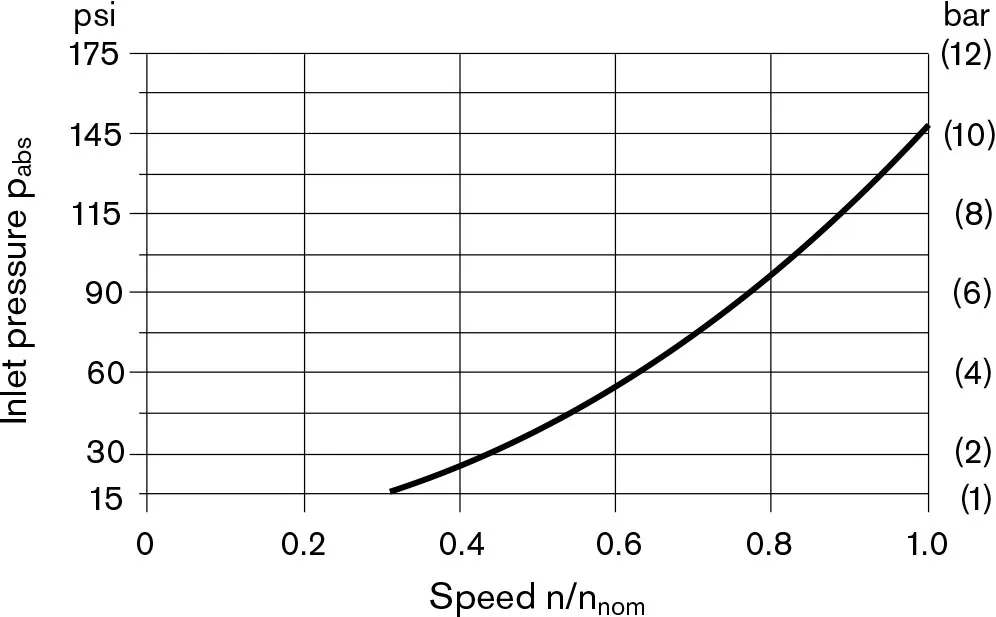
This diagram is valid only for the optimum viscosity range from νopt = 170 to 74 SUS (36 to 16 mm2/s).
Please contact us if these conditions cannot be satisfied.
Definition
Nominal pressure Pnom
The nominal pressure corresponds to the maximum design pressure.
Maximum pressure Pmax
The maximum pressure corresponds to the maximum operating pressure within the single operating period. The sum of the single operating periods must not exceed the total operating period.
Minimum pressure (high-pressure side)
Minimum pressure at the high-pressure side (A or B) which is required in order to prevent damage to the axial piston unit.
Summation pressure pSu
The summation pressure is the sum of the pressures at both service line ports (A and B).
Rate of pressure change RA
Maximum permissible rate of pressure rise and reduction during a pressure change over the entire pressure range.
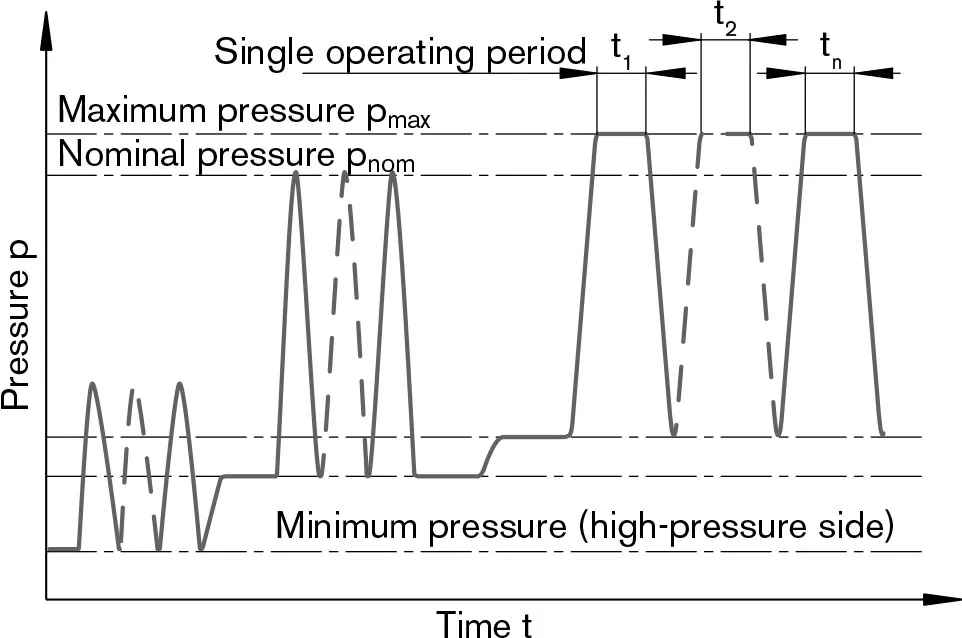
Total operating period = t1 +t2+... +tn
Table of values (theoretical values, without efficiency and tolerances; values rounded)
| Size | NG | 10 | 12 | 16 | 23 | 28 | 32 | 45 | 56 | ||
| Displacement geometric, per revolution |
Vg | in3 | 0.63 | 0.73 | 0.98 | 1.40 | 1.71 | 1.95 | 2.78 | 3.42 | |
| cm3 | 10.3 | 12 | 16 | 22.9 | 28.1 | 32 | 45.6 | 56.1 | |||
| Speed maximum1) | nnom | rpm | 8000 | 8000 | 8000 | 6300 | 6300 | 6300 | 5600 | 5000 | |
| nmax2) | rpm | 8800 | 8800 | 8800 | 6900 | 6900 | 6900 | 6200 | 5500 | ||
| Input flow3) | gpm | 21.8 | 25.3 | 33.9 | 38.2 | 46.8 | 53.4 | 67.4 | 74.2 | ||
| at nnom and Vg | qv | L/min | 82 | 96 | 128 | 144 | 177 | 202 | 255 | 281 | |
| Torque4) | Δp= 5100 psi | T | lb-ft | 42 | 49 | 66 | 94 | 116 | 132 | 188 | 231 |
| at Vg and | Δp = 350 bar | T | Nm | 57 | 67 | 89 | 128 | 157 | 178 | 254 | 313 |
| Δp = 5800 psi | T | lb-ft | 49 | 56 | 75 | 108 | 132 | 150 | 213 | 263 | |
| Δp =400 bar | T | Nm | 66 | 76 | 102 | 146 | 179 | 204 | 290 | 357 | |
| Rotary stiffness | c | kNm/rad | 0.92 | 1.25 | 1.59 | 2.56 | 2.93 | 3.12 | 4.18 | 5.94 | |
| Moment of inertia for rotary group |
JGR | lbs-ft2 | 0.0095 | 0.0095 | 0.0095 | 0.0285 | 0.0285 | 0.0285 | 0.0569 | 0.0997 | |
| kgm2 | 0.0004 | 0.0004 | 0.0004 | 0.0012 | 0.0012 | 0.0012 | 0.0024 | 0.0042 | |||
| Maximum angular acceleration |
α | rad/s2 | 5000 | 5000 | 5000 | 6500 | 6500 | 6500 | 14600 | 7500 | |
| Case volume | V | gal | 0.045 | 0.045 | 0.045 | 0.053 | 0.053 | 0.053 | 0.087 | 0.119 | |
| L | 0.17 | 0.17 | 0.17 | 0.20 | 0.20 | 0.20 | 0.33 | 0.45 | |||
| Mass (approx.) | m | lbs | 12 | 12 | 12 | 21 | 21 | 21 | 30 | 40 | |
| kg | 5.4 | 5.4 | 5.4 | 9.5 | 9.5 | 9.5 | 13.5 | 18 | |||
| Size | NG | 63 | 80 | 90 | 107 | 125 | 160 | 180 | 250 | ||
| Displacement geometric, per revolution |
Vg | in3 | 3.84 | 4.91 | 5.49 | 6.51 | 7.63 | 9.79 | 10.98 | 15.25 | |
| cm3 | 63 | 80.4 | 90 | 106.7 | 125 | 160.4 | 180 | 250 | |||
| Speed maximum1) | nnom | rpm | 5000 | 4500 | 4500 | 4000 | 4000 | 3600 | 3600 | 2700 | |
| nmax2) | rpm | 5500 | 5000 | 5000 | 4400 | 4400 | 4000 | 4000 | - | ||
| Input flow3) | gpm | 83.1 | 95.6 | 106.9 | 112.7 | 132.1 | 152.5 | 171.1 | 178 | ||
| at nnom and Vg | qv | L/min | 315 | 362 | 405 | 427 | 500 | 577 | 648 | 675 | |
| Torque4) | Δp= 5100 psi | T | lb-ft | 259 | 330 | 371 | 438 | 513 | 659 | 740 | 1030 |
| at Vg and | Δp = 350 bar | T | Nm | 351 | 448 | 501 | 594 | 696 | 893 | 1003 | 1393 |
| Δp = 5800 psi | T | lb-ft | 296 | 378 | 423 | 501 | 587 | 753 | 845 | - | |
| Δp =400 bar | T | Nm | 401 | 512 | 573 | 679 | 796 | 1021 | 1146 | - | |
| Rotary stiffness | c | kNm/rad | 6.25 | 8.73 | 9.14 | 11.2 | 11.9 | 17.4 | 18.2 | 73.1 | |
| Moment of inertia for rotary group |
JGR | lbs-ft2 | 0.0997 | 0.1708 | 0.1708 | 0.2753 | 0.2753 | 0.5221 | 0.5221 | 1.4475 | |
| kgm2 | 0.0042 | 0.0072 | 0.0072 | 0.0116 | 0.0116 | 0.0220 | 0.0220 | 0.061 | |||
| Maximum angular acceleration |
α | rad/s2 | 7500 | 6000 | 6000 | 4500 | 4500 | 3500 | 3500 | 10000 | |
| Case volume | V | gal | 0.119 | 0.145 | 0.145 | 0.211 | 0.211 | 0.291 | 0.291 | 0.660 | |
| L | 0.45 | 0.55 | 0.55 | 0.8 | 0.8 | 1.1 | 1.1 | 2.5 | |||
| Mass (approx.) | m | lbs | 40 | 51 | 51 | 71 | 71 | 99 | 99 | 161 | |
| kg | 18 | 23 | 23 | 32 | 32 | 45 | 45 | 73 | |||
1)The values are valid:
- for the optimum viscosity range from
νopt = 170 to 74 SUS (36 to 16 mm2/s)
- with hydraulic fluid based on mineral oils
2)Intermittent maximum speed: overspeed for unload and overhauling processes, t <5 s and Δp <2200 psi (150 bar)
3) Restriction of input flow with counterbalance valve, see page 32
4) Torque without radial force, with radial force see page 9
Note
Operation above the maximum values or below the minimum values may result in a loss of function, a reduced service life or in the destruction of the axial piston unit. Other permissible limit values, with respect to speed variation, reduced angular acceleration as a function of the frequency and the permissible start up angular acceleration (lower than the maximum angular acceleration) can be found in data sheet RE 90261.
Determining the operating characteristics
| Input flow | qv=(Vg∙n)/(231∙ηv) | gpm | (qv=(Vg∙n)/(1000∙ηv) L/min) |
| Speed | n=(qv∙231∙ηv)/Vg | rpm | (n=(qv∙1000∙ηv)/Vg rpm) |
| Torque | T=(Vg∙Δp∙ηmh)/(24∙π) | lb-ft | (T=(Vg∙Δp∙ηmh)/(20∙π) Nm) |
| Power | P=(2π∙T∙n)/33000=(qv∙Δp∙ηt)/1714 | HP | (P=(2π∙T∙n)/60000=(qv∙Δp∙ηt)/600 kW) |
Vg = Displacement per revolution in in3 (cm3)
Δp = Differential pressure in psi (bar)
n = Speed in rpm
ηv= Volumetric efficiency
ηmh = Mechanical-hydraulic efficiency
ηt = Total efficiency (ηt=ηt∙ηmn)
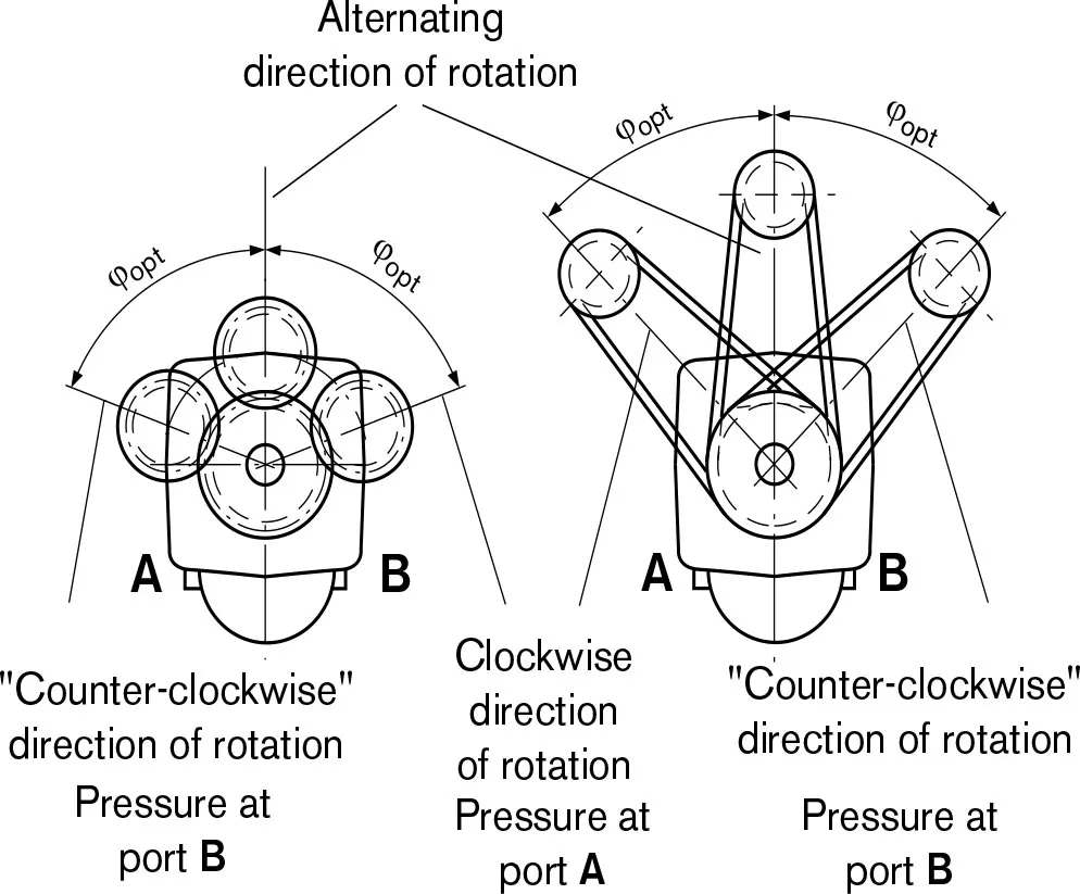
Effect of radial force Fq on the service life of bearings
By selecting a suitable direction of radial force Fq, the load on the bearings, caused by the internal rotary group forces can be reduced, thus optimizing the service life of the bearings. Recommended position of mating gear is dependent on direction of rotation. Examples:
| Toothed gear drive | V-belt output | |
| NG | φopt | φopt |
| 10 to 180 | ±70° | ±45° |
| 250 | ±45° | ±70° |
Permissible radial and axial forces of the drive shafts(splined shaft and parallel keyed shaft)
| Size | NG | 10 | 10 | 10 | 12 | 12 | 12 | 163) | 16 | ||
| Drive shaft | Φ | in | 7/8 | 0.79 | 0.98 | 7/8 | 0.79 | 0.98 | 7/8 | 0.98 | |
| mm | - | 20 | 25 | - | 20 | 25 | - | 25 | |||
| Maximum radial force1) at distance a (from shaft collar) |
 |
Fq max | lbf | 629.5 | 674.4 | 719.4 | 741.9 | 674.4 | 719.4 | 966.7 | 719.4 |
| kN | 2.8 | 3.0 | 3.2 | 3.3 | 3.0 | 3.2 | 4.3 | 3.2 | |||
| a | in | 0.63 | 0.63 | 0.63 | 0.63 | 0.63 | 0.63 | 0.63 | 0.63 | ||
| mm | 16.8 | 16 | 16 | 16.8 | 16 | 16 | 16.8 | 16 | |||
| with permissible torque | Tmax | lb-ft | 47.9 | 49 | 47.9 | 56.1 | 56.1 | 56.9 | 72.3 | 73.8 | |
| Nm | 65 | 66 | 65 | 76 | 76 | 76 | 98 | 100 | |||
| ≜ permissible pressure Δp | Δp perm | psi | 5800 | 5800 | 5800 | 5800 | 5800 | 5800 | 5550 | 5800 | |
| bar | 400 | 400 | 400 | 400 | 400 | 400 | 385 | 400 | |||
| Maximum axial force2) |  |
-Fax max | lbf | 71.9 | 71.9 | 71.9 | 71.9 | 71.9 | 71.9 | 71.9 | 71.9 |
| N | 320 | 320 | 320 | 320 | 320 | 320 | 320 | 320 | |||
| +Fax max | N | 0 | 0 | 0 | 0 | 0 | 0 | 0 | 0 | ||
| Permissible axial force per psi (bar) operating pressure |
±Fax perm/bar | lbf/psi | 0.05 | 0.05 | 0.05 | 0.05 | 0.05 | 0.05 | 0.05 | 0.05 | |
| N/bar | 3.0 | 3.0 | 3.0 | 3.0 | 3.0 | 3.0 | 3.0 | 3.0 | |||
| Size | NG | 23 | 23 | 23 | 28 | 28 | 28 | 32 | 32 | ||
| Drive shaft | Φ | in | 1 1/4 | 0.98 | 1.18 | 1 1/4 | 0.98 | 1.18 | 1 1/4 | 1.18 | |
| mm | - | 25 | 30 | - | 25 | 30 | - | 30 | |||
| Maximum radial force1) at distance a (from shaft collar) |
|
Fq max | lbf | 809.3 | 1281.4 | 1213.9 | 989.1 | 1281.4 | 1213.9 | 1146.5 | 1213.9 |
| kN | 3.6 | 5.7 | 5.4 | 4.4 | 5.7 | 5.4 | 5.1 | 5.4 | |||
| a | in | 0.94 | 0.63 | 0.63 | 0.94 | 0.63 | 0.63 | 0.94 | 0.63 | ||
| mm | 24 | 16 | 16 | 24 | 16 | 16 | 24 | 16 | |||
| with permissible torque | Tmax | lb-ft | 106.2 | 108 | 106.2 | 131.3 | 132 | 131.3 | 150.5 | 150.5 | |
| Nm | 144 | 146 | 144 | 178 | 179 | 178 | 204 | 204 | |||
| ≜ permissible pressure Δp | Δp perm | psi | 5800 | 5800 | 5800 | 5800 | 5800 | 5800 | 5800 | 5800 | |
| bar | 400 | 400 | 400 | 400 | 400 | 400 | 400 | 400 | |||
| Maximum axial force2) | |
-Fax max | lbf | 112.2 | 112.2 | 112.2 | 112.2 | 112.2 | 112.2 | 112.2 | 112.2 |
| N | 500 | 500 | 500 | 500 | 500 | 500 | 500 | 500 | |||
| +Fax max | N | 0 | 0 | 0 | 0 | 0 | 0 | 0 | 0 | ||
| Permissible axial force per psi (bar) operating pressure |
±Fax perm/bar | lbf/psi | 0.08 | 0.08 | 0.08 | 0.08 | 0.08 | 0.08 | 0.08 | 0.08 | |
| N/bar | 5.2 | 5.2 | 5.2 | 5.2 | 5.2 | 5.2 | 5.2 | 5.2 | |||
1) With intermittent operation
2) Maximum permissible axial force during standstill or when the axial piston unit is operating in non-pressurized condition.
3) Restricted technical data
Note
Influence of the direction of the permissible axial force:
+Fax max=Increase in service life of bearings
-Fax max=Reduction in service life of bearings (avoid)
| Size | NG | 45 | 45 | 563) | 56 | 56 | 56 | 633) | 63 | 63 | ||
| Drive shaft | Φ | in | 1 1/4 | 1.18 | 1 1/4 | 1 3/8 | 1.18 | 1.37 | 1 1/4 | 1 3/8 | 1.38 | |
| mm | - | 30 | - | - | 30 | 35 | - | - | 35 | |||
| Maximum radial force1) at distance a (from shaft collar) |
 |
Fq max | lbf | 1641 | 1709 | 1709 | 2068 | 2136 | 2045 | 1708 | 2315 | 2046 |
| kN | 7.3 | 7.6 | 7.6 | 9.2 | 9.5 | 9.1 | 7.6 | 10.3 | 9.1 | |||
| a | in | 0.94 | 0.71 | 0.94 | 0.94 | 0.71 | 0.71 | 0.94 | 0.94 | 0.71 | ||
| mm | 24 | 18 | 24 | 24 | 18 | 18 | 24 | 24 | 18 | |||
| with permissible torque | Tmax | lb-ft | 214 | 214 | 223 | 263 | 263 | 263 | 223 | 295 | 295 | |
| Nm | 290 | 290 | 302 | 356 | 357 | 356 | 302 | 400 | 400 | |||
| ≜ permissible pressure Δp | Δp perm | psi | 5800 | 5800 | 4950 | 5800 | 5800 | 5800 | 4350 | 5800 | 5800 | |
| bar | 400 | 400 | 339 | 400 | 400 | 400 | 301 | 400 | 400 | |||
| Maximum axial force2) |  |
-Fax max | lbf | 142 | 142 | 180 | 180 | 180 | 180 | 180 | 180 | 180 |
| N | 630 | 630 | 800 | 800 | 800 | 800 | 800 | 800 | 800 | |||
| +Fax max | N | 0 | 0 | 0 | 0 | 0 | 0 | 0 | 0 | 0 | ||
| Permissible axial force per psi (bar) operating pressure |
±Fax perm/bar | lbf/psi | 0.11 | 0.11 | 0.13 | 0.13 | 0.13 | 0.13 | 0.13 | 0.13 | 0.13 | |
| N/bar | 7.0 | 7.0 | 8.7 | 8.7 | 8.7 | 8.7 | 8.7 | 8.7 | 8.7 | |||
| Size | NG | 803) | 803) | 80 | 80 | 903) | 903 | 90 | 1073) | 107 | ||
| Drive shaft | Φ | in | 1 1/4 | 1 3/8 | 1.37 | 1.57 | 1 1/4 | 1 3/8 | 1.57 | 1 1/2 | 1 3/4 | |
| mm | - | - | 35 | 40 | - | - | 40 | - | - | |||
| Maximum radial force1) at distance a (from shaft collar) |
|
Fq max | lbf | 1709 | 2608 | 2608 | 2563 | 1709 | 2608 | 2563 | 2788 | 2743 |
| kN | 7.6 | 11.6 | 11.6 | 11.4 | 7.6 | 11.6 | 11.4 | 12.4 | 12.2 | |||
| a | in | 0.94 | 0.94 | 0.79 | 0,79 | 0.94 | 0.94 | 0.79 | 1.06 | 1.32 | ||
| mm | 24 | 24 | 20 | 20 | 24 | 24 | 20 | 27 | 33.5 | |||
| with permissible torque | Tmax | lb-ft | 223 | 332 | 378 | 378 | 223 | 332 | 423 | 438 | 502 | |
| Nm | 302 | 450 | 512 | 512 | 302 | 450 | 573 | 594 | 680 | |||
| ≜ permissible pressure Δp | Δp perm | psi | 3450 | 5100 | 5800 | 5800 | 3050 | 4550 | 5800 | 5100 | 5800 | |
| bar | 237 | 352 | 400 | 400 | 211 | 314 | 400 | 349 | 400 | |||
| Maximum axial force2) | |
-Fax max | lbf | 225 | 225 | 225 | 225 | 225 | 225 | 225 | 281 | 281 |
| N | 1000 | 1000 | 1000 | 1000 | 1000 | 1000 | 1000 | 1250 | 1250 | |||
| +Fax max | N | 0 | 0 | 0 | 0 | 0 | 0 | 0 | 0 | 0 | ||
| Permissible axial force per psi (bar) operating pressure |
±Fax perm/bar | lbf/psi | 0.16 | 0.16 | 0.16 | 0.16 | 0.16 | 0.16 | 0.16 | 0.20 | 0.20 | |
| N/bar | 10.6 | 10.6 | 10.6 | 10.6 | 10.6 | 10.6 | 10.6 | 12.9 | 12.9 | |||
1.With intermittent operation
2.Maximum permissible axial force during standstill or when theaxial piston unit is operating in non-pressurized condition.
3.Restricted technical data
Note
Influence of the direction of the permissible axial force:
+Fax max=Increase in service life of bearings
-Fax max=Reduction in service life of bearings (avoid)
| Size | NG | 107 | 107 | 1253) | 125 | 125 | 1603) | 160 | 160 | 1803) | 180 | ||
| Drive shaft | Φ | in | 1.57 | 1.77 | 1 1/2 | 1 3/4 | 1.77 | 1 3/4 | 1.77 | 1.97 | 1 3/4 | 1.97 | |
| mm | 40 | 45 | - | - | 45 | - | 45 | 50 | - | 50 | |||
| Maximum radial force1) at distance a (from shaft collar) |
|
Fq max | lbf | 3057 | 3169 | 2788 | 3215 | 3170 | 3350 | 4069 | 4114 | 3350 | 4114 |
| kN | 13.6 | 14.1 | 12.4 | 14.3 | 14.1 | 14.9 | 18.1 | 18.3 | 14.9 | 18.3 | |||
| a | in | 0.79 | 0.79 | 1.06 | 1.32 | 0.79 | 1.32 | 0.98 | 0.98 | 1.32 | 0.98 | ||
| mm | 20 | 20 | 27 | 33.5 | 20 | 33.5 | 25 | 25 | 33.5 | 25 | |||
| with permissible torque | Tmax | lb-ft | 501 | 502 | 438 | 587 | 587 | 611 | 753 | 749 | 611 | 844 | |
| Nm | 679 | 680 | 594 | 796 | 796 | 828 | 1021 | 1016 | 828 | 1144 | |||
| ≜ permissible pressure Δp | Δp perm | psi | 5800 | 5800 | 4350 | 5800 | 5800 | 4700 | 5800 | 5800 | 4200 | 5800 | |
| bar | 400 | 400 | 298 | 400 | 400 | 325 | 400 | 400 | 289 | 400 | |||
| Maximum axial force2) | |
-Fax max | lbf | 281 | 281 | 281 | 281 | 281 | 360 | 360 | 360 | 360 | 360 |
| N | 1250 | 1250 | 1250 | 1250 | 1250 | 1600 | 1600 | 1600 | 1600 | 1600 | |||
| +Fax max | N | 0 | 0 | 0 | 0 | 0 | 0 | 0 | 0 | 0 | 0 | ||
| Permissible axial force per psi (bar) operating pressure |
±Fax perm/bar | lbf/psi | 0.20 | 0.20 | 0.20 | 0.20 | 0.20 | 0.26 | 0.26 | 0.26 | 0.26 | 0.26 | |
| N/bar | 12.9 | 12.9 | 12.9 | 12.9 | 12.9 | 16.7 | 16.7 | 16.7 | 16.7 | 16.7 | |||
| Size | NG | 250 | ||
| Drive shaft | Φ | in | 1.97 | |
| mm | 50 | |||
| Maximum radial force1) at distance a (from shaft collar) |
|
Fq max | lbf | 2705) |
| kN | 1.25) | |||
| a | in | 1.61 | ||
| mm | 41 | |||
| with permissible torque | Tmax | lb-ft | 1027 | |
| Nm | 1393 | |||
| ≜ permissible pressure Δp | Δp perm | psi | 5100 | |
| bar | 350 | |||
| Maximum axial force2) | |
-Fax max | lbf | 450 |
| N | 2000 | |||
| +Fax max | N | 0 | ||
| Permissible axial force per psi (bar) operating pressure |
±Fax perm/bar | lbf/psi | 4) | |
| N/bar | ||||
1)With intermittent operation
2)Maximum permissible axial force during standstill or when theaxial piston unit is operating in non-pressurized condition.
3) Restricted technical data
4) Please contact us.
5) When at a standstill or when axial piston unit operating in non-pressurized conditions. Higher forces are permissible when under pressure, please contact us.
Note
Influence of the direction of the permissible axial force:
+Fax max = Increase in service life of bearings
-Fax max = Reduction in service life of bearings (avoid)
