Wenzhou Prance Hydraulic Equipment Co., Ltd

")
")
")
")
")
.")
Industrial Variable Piston Pump A10VO 32 Series
1.Variable Displacment Axial piston Pump of swashplate design for hydraulic open circuit system
2.Flow is proportional to drive speed and displacment .It can be infinitely Varied by adjustment of the swashplate
3.ISO Mounting Flange
4.Flange connections to SAE metric
5.2 case drain ports
6.Good suction Characteristics
Detailed description
This is a swashplate-designed variable displacement axial piston pump specially engineered for hydraulic open circuit systems. Its output flow is strictly proportional to the driving speed and displacement volume. By precisely adjusting the swashplate angle, the pump displacement can be steplessly and infinitely varied to accurately match different flow and pressure demands of the hydraulic system. The pump adopts standard ISO mounting flange design, which ensures convenient installation, reliable positioning and strong versatility for equipment assembly. It is configured with flange connections complying with SAE metric specifications, realizing standardised pipeline matching and easy modular connection. Two independent case drain ports are reserved for smooth discharge of internal leakage oil and effective heat dissipation. Meanwhile, the pump delivers excellent suction performance and stable suction characteristics, enabling reliable operation under normal working conditions and adapting to various complex hydraulic application scenarios.
Selection and RFQ
This product series should be selected against the approved hydraulic circuit. Confirm required flow or displacement, continuous and peak pressure, drive speed, control arrangement, fluid and installation interface before final selection.
Information to include in your RFQ
- Required displacement or flow at operating speed
- Continuous and peak system pressure
- Drive speed, control requirement and circuit type
- Mounting flange, shaft, ports, fluid and filtration requirement
Related resources
Ordering code
| 01 | 02 | 03 | 04 | 05 | 06 | 07 | 08 | 09 | 10 | 11 | 12 | ||
| A10V | ○ | / | 32 | - | v |
Axial piston unit
| 01 | Swashplate design, variable, nominal pressure 280 bar, maximum pressure 350 bar | A10V |
Operation mode
| 02 | Pump, open circuit | ○ |
Size(NG)
| 03 | Geometric displacement, see "Technical data" on page 7 | 045 | 071 | 100 | 140 | 180 |
Control devices
| 04 | Pressure controller | Hydraulic | ● | ● | ● | ● | ● | DR | |||
| with flow controller | Hydraulic | X-T open | ● | ● | ● | ● | ● | DRF | |||
| X-T plugged | with flushing function | ● | ● | ● | ● | ● | DRS | ||||
| X-T plugged | without flushing function | ● | ● | ● | ● | ● | DRSC | ||||
| Pressure cut-off | Hydraulic | remotely controlled | ● | ● | ● | ● | ● | DRG | |||
| electrical | negative control | U=12V | ● | ● | ● | ● | ● | ED71 | |||
| U=24V | ● | ● | ● | ● | ● | ED72 | |||||
| electrical | positive control | U=12V | ● | ● | ● | ● | ● | ER711) | |||
| U=24V | ● | ● | ● | ● | ● | ER722) | |||||
| Differential pressure
control |
electrical | negative control | see data sheet 92709 | ● | ● | ● | ● | ○ | EF. | ||
| Power controller with | |||||||||||
| Pressure cut-off | Hydraulic | Beginning of control | to | 50 bar | ● | ● | ● | ● | ● | LA5D | |
| from | 51 to 90 bar | ● | ● | ● | ● | ● | LA6D | ||||
| 91 to 160 bar | ● | ● | ● | ● | ● | LA7D | |||||
| 161 to 240 bar | ● | ● | ● | ● | ● | LA8D | |||||
| above | 240 bar | ● | ● | ● | ● | ● | LA9D | ||||
| Pressure cut-off and flow control | Hydraulic | Beginning of control | see LA.D | ● | ● | ● | ● | ● | LA.DS | ||
| Remote-controlled
pressure cut-off |
Hydraulic | Beginning of control | see LA.D | ● | ● | ● | ● | ● | LA.DG | ||
| Separate flow control | Hydraulic | Beginning of control | see LA.D | ● | ● | ● | ● | ● | LA.S | ||
Series
| 05 | Series 3, index 2 | 32 |
Direction of rotation
| 06 | Viewed on drive shaft | clockwise | R |
| counter-clockwise | L |
Seal
| 07 | FKM (fluoroelastomer) | V |
Drive shaft
| 08 | Splined shaft
ANSI B92.1a |
standard shaft | ● | ● | ● | ● | ● | S |
| similar to shaft "S" however for higher input torque | ● | ● | - | - | - | R | ||
| reduced diameter, limited suitability for through drive | ● | ● | ● | ● | - | U | ||
| same as shaft "U", but for higher torque, limited suitability for through drive | - | - | ● | ● | ● | W |
Mounting flange
| 045 | 071 | 100 | 140 | 180 | 045 | |||
| 09 | ISO 3019-1 (SAE) | SAE C; 2-hole | ● | ● | ● | ● | - | C |
| SAE C; 4-hole | ● | ● | ● | ● | ● | D | ||
| SAE D; 4-hole | - | ● | - | - | - | U |
Working port
| 10 | SAE flange port (Port plates and through drive assignment,
see position 11) |
rear, metric fastening thread (not for through drive) | ● | ● | ● | ● | ● | 11 |
| at top, at bottom, on opposite side, metric fastening thread | ● | ● | ● | ● | - | 12 | ||
| at top, at bottom, on opposite side, metric fastening thread with universal through drive U..; without pulsation damping | ○ | ○ | ○ | ○ | ● | 221) | ||
| at top, at bottom, on opposite side, metric fastening thread with universal through drive U..; with pulsation damping | ○ | ○ | ○ | ○ | ● | 321) |
Through drive
| 11 | Flange IS0 3019-1
Diameter |
Attach-
ment4) |
Hub for splined shaft2)
Diameter |
|||||||
| 045 | 071 | 100 | 140 | 180 | ||||||
| without through drive | (Only for port plates 11 and 12) | ● | ● | ● | ● | ● | N00 | |||
| 82-2 (A) | 5/8 in | 9T 16/32DP | ● | ● | ● | ● | - | K01 | ||
| 3/4 in | 11T 16/32DP | ● | ● | ● | ● | - | K52 | |||
| 101-2 (B) | 7/8in | 13T 16/32DP | ● | ● | ● | ● | - | K68 | ||
| 1in | 15T 16/32DP | ● | ● | ● | ● | - | K04 | |||
| 127-2 (C) | 1 1/4in | 14T 12/24DP | - | ● | ● | ● | - | K07 | ||
| 1 1/2 in | 17T12/24DP | - | - | ● | ● | - | K24 | |||
| 127-4 (C) | 1 1/4 in | 14T 12/24DP | - | ○ | ● | ● | - | K15 | ||
| 152-4 (D) | 1 3/4 in | 13T 8/16DP | - | - | - | ● | - | K17 | ||
| without through drive | (Only possible with port plates 22 and 32)3) | ○ | ○ | ○ | ○ | ● | U00 | |||
| 82-2 (A) | 5/8 in | 9T 16/32DP | ○ | ○ | ○ | ○ | ● | U01 | ||
| 3/4 in | 13T 16/32DP | ○ | ○ | ○ | ○ | ● | U52 | |||
| 101-2(B) | 7/8in | 13T 16/32DP | ○ | ○ | ○ | ○ | ● | U68 | ||
| 1in | 15T 16/32DP | ○ | ○ | ○ | ○ | ● | U04 | |||
| 127-2 (C) | 1 1/4in | 14T 12/24DP | - | ○ | ○ | ○ | ● | U07 | ||
| 1 1/2 in | 17T 12/24DP | - | - | ○ | ○ | ● | U24 | |||
| 127-4 (C) | 1 in | 15T 16/32DP | ○ | ○ | ○ | ○ | ○ | UE2 | ||
| 1 1/4 in | 14T 12/24DP | - | - | ○ | ○ | ● | U15 | |||
| 152-4 (D) | 1 3/4 in | 13T 8/16DP | - | - | - | ○ | ● | U17 | ||
Connectors for solenoids5)
| 12 | Without connector (without solenoid, with hydraulic control only, without code) | |
| DEUTSCH molded connector, 2-pin - without suppressor diode | P |
•=Available ○=On request -=Not available
Notes
Note the project planning notes on page 54!
In addition to the type code, please specify the relevant technical data when placing your order.
1)Only with mounting flange (ordering code position 09) D or U
2)According to ANSI B92.1a (splined shafts according to SAE J744)
3)With through-drive shaft, without hub, without intermediate flange,closed on a functionally reliable basis with cover. For mounting kits,see data sheet 95581.
4)Mounting through bores pattern viewed from through drive with control at top.
5)Connectors for other electric components may deviate.
Technical data
| Size | NG | 045 | 071 | 100 | 140 | 180 | |||
| Displacement, geometric, per revolution | Vg max | cm3 | 45 | 71.1 | 100 | 140 | 180 | ||
| Maximum rotational speed1)2) | at | Vg max | nnom | rpm | 3000 | 2550 | 2300 | 2200 | 1800 |
| Flow | at | nnom and Vg max | qv | I/min | 135 | 181 | 230 | 308 | 324 |
| Power | at | nnom, Vg max and Δp = 280 bar | P | kW | 63 | 85 | 107 | 144 | 151 |
| Torque | at | Vg max and Δp = 280 bar | T | Nm | 200 | 317 | 446 | 624 | 802 |
| at | Vg max and Δp = 100 bar | T | Nm | 72 | 113 | 159 | 223 | 286 | |
| Rotary stiffness ofdrive shaft | S | c | Nm/rad | 37500 | 71884 | 121142 | 169537 | 171107 | |
| R | c | Nm/rad | 41025 | 76545 | - | - | - | ||
| U | c | Nm/rad | 30077 | 52779 | 91093 | on | - | ||
| request | |||||||||
| W | c | Nm/rad | 34463 | 57460 | 101847 | 165594 | - | ||
| Moment of inertia for rotary group | JTW | Kgm2 | 0.0035 | 0.0087 | 0.0167 | 0.0242 | 0.033 | ||
| Maximum angular acceleration3) | α | rad/s2 | 4000 | 2900 | 2400 | 2000 | 2000 | ||
| Case volume | V | L | 1.0 | 1.6 | 2.2 | 3.0 | 2.7 | ||
| Weight (11N00 and 12N00 without through drive) approx. | m | kg | 25.8 | 40.4 | 56.4 | 70.5 | 75.2 | ||
| Weight (12Kxx) approx. | m | kg | 27.4 | 43.3 | 62.6 | 79.5 | - | ||
| Weight (22Uxx/32Uxx)approx. | m | kg | 32.6 | 51.8 | 76 | 90.2 | 89.4 | ||
Determining the operating characteristics
| Flow | qv=(Vg ∙ n ∙ ηv) / 1000 | I/min |
| Torque | T=(Vg ∙ Δp) / 20 ∙ π ∙ ηmh | Nm |
| Power | P=(2π ∙ T ∙ n)/60000=(qv ∙ Δp)/600 ∙ ηt | kW |
Key
Vg Displacement per revolution in [cm3]
Δp Differential pressure [bar]
n Rotational speed [rpm]
ηv Volumetric efficiency
ηmh Hydraulic-mechanical efficiency
ηt Total efficiency (ηt= ηv*ηhm)
Notice
▶Theoretical values, without efficiency and tolerances;values rounded
▶Operation above the maximum values or below the minimum values may result in a loss of function, a reduced service life or in the destruction of the axial piston unit. Bosch Rexroth recommend testing the load by means of experiment or calculation/simulation and comparison with the permissible values.
1) The values are applicable:
- to the optimum viscosity range from Vopt = 36 to 16 mm2/s
- to hydraulic fluid based on mineral oils
2) The values apply at absolute pressure pabs = 1.0 bar at suction port S.
3)The data are valid for values between the minimum required and maximum permissible rotational speed. Valid for external excitation(e.g. diesel engine 2 to 8 times rotary frequency, cardan shaft twice the rotary frequency). The limit value is only valid for a single pump.The load capacity of the connecting parts must be considered.
Permissible radial and axial forces on the drive shaft
| Size | NG | 45 | 71 | 100 | 140 | 180 | ||
| Maximum radial force at a/2 |  |
Fq max | N | 1500 | 1900 | 2300 | 2800 | 2300 |
| Maximum axial force | ±Fax max | N | 1500 | 2400 | 4000 | 4800 | 800 | |
Notice
▶For drives with radial loading (pinion, V-belt), please contact us!
▶The values given are maximum values and do not apply to continuous operation.
Permissible input and through-drive torques
| Size | 45 | 71 | 100 | 140 | 180 | |||
| Torque at Vg max and Δp = 280 bar1) | Tmax | Nm | 200 | 316 | 446 | 624 | 802 | |
| Input torque at drive shaft, maximum2) | ||||||||
| S | TE max | Nm | 319 | 626 | 1104 | 1620 | 1834 | |
| ∅ | in | 1 | 1 1/4 | 1 1/2 | 1 3/4 | 1 3/4 | ||
| R | TE max | Nm | 400 | 644 | - | - | - | |
| ∅ | in | 1 | 1 1/4 | - | - | - | ||
| U | TE max | Nm | 188 | 300 | 595 | on
request |
- | |
| ∅ | in | 7/8 | 1 | 1 1/4 | 1 1/2 | - | ||
| W | TE max | Nm | - | 394 | 636 | 1220 | 1488 | |
| ∅ | in | - | 1 | 1 1/4 | 1 1/2 | 1 1/2 | ||
| Maximum through-drive torque | ||||||||
| S | TD max | Nm | 319 | 492 | 778 | 1266 | 1266 | |
| R | TD max | Nm | 365 | 548 | - | - | - | |
| U | TD max | Nm | 188 | - | 595 | on
request |
- | |
| W | TD max | Nm | - | - | 636 | 1220 | 1266 | |
Distribution of torques
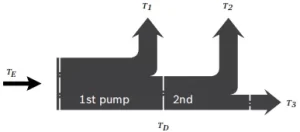
| Torque at 1st pump | T1 |
| Torque at 2nd pump | T2 |
| Torque at 3rd pump | T3 |
| Input torque | TE=T1+T2+T3 |
| TE < TE max | |
| Through∙drive torque | TD=T2+T3 |
| TD < TD max |
1)Efficiency not considered
2) For drive shafts with no radial force
