Wenzhou Prance Hydraulic Equipment Co., Ltd

")
")
")
")
")
")
Variable Axial Pump A10VZO
1.Suitable for start/stop operations
2.Suitable for long-term pressure holding operations
3.Well-tried A10 rotary assembly technology
4.optional through-shaft drive
5.high efficiency
6.for first, second and fourth quadrant operations
Detailed description
This hydraulic pump is designed with excellent adaptability to various working conditions, being fully suitable for frequent start/stop operations without affecting its service life or performance stability, which makes it ideal for scenarios requiring intermittent operation. It also performs reliably in long-term pressure holding operations, maintaining stable pressure output for extended periods without obvious pressure loss, effectively meeting the requirements of systems that need continuous pressure retention. The pump adopts well-tried and mature A10 rotary assembly technology, which has been verified through long-term practical application, ensuring high operational stability, low failure rate and easy maintenance. For enhanced versatility, it offers an optional through-shaft drive, allowing flexible connection with other components and expanding its application scope in complex hydraulic systems. Additionally, the pump features high efficiency, which can effectively convert input power into hydraulic energy, reducing energy consumption and improving the overall operational efficiency of the system. It is also compatible with first, second and fourth quadrant operations, enabling bidirectional energy flow and adapting to diverse motion control requirements of hydraulic drives.
Selection and RFQ
This product series should be selected against the approved hydraulic circuit. Confirm required flow or displacement, continuous and peak pressure, drive speed, control arrangement, fluid and installation interface before final selection.
Information to include in your RFQ
- Required displacement or flow at operating speed
- Continuous and peak system pressure
- Drive speed, control requirement and circuit type
- Mounting flange, shaft, ports, fluid and filtration requirement
Related resources
Type code A10VZ0
| 01 | 02 | 03 | 04 | 05 | 06 | 07 | 08 | 09 | 10 | 11 | 12 | 13 | ||
| A10V | Z | ○ | / | 10 | - | V | C | N00 |
Axial piston unit
| 01 | Swashplate design, variable | A10V |
Application area
| 02 | Variable-speed drives | Z |
Operating mode
| 03 | Pump, open circuit | ○ |
Size(NG)
| 04 | Geometric displacement, see table of values on page 31 | 010 | 018 | 028 | 045 | 071 | 100 | 140 | 180 |
| Other available intermediate sizes | 003,006,008 |
Control device
| 05 | Two-point control | electrical | U=12V | ● | ● | ● | ● | ○ | ○ | ○ | ○ | EZ3001) |
| U=24V | ● | ● | ● | ● | ○ | ○ | ○ | ○ | EZ4001) | |||
| hydraulic | ● | ● | ● | ● | ○ | ○ | ○ | ○ | DGO001) | |||
| Pressure controller | hydraulic | ● | ● | ● | ● | ○ | ○ | ○ | ○ | DRO00 | ||
| remote controlled hydraulically | ● | ● | ● | ● | ○ | ○ | ○ | ○ | DRGO0 | |||
| Torque controller | Size 018 to 180 | |||||||||||
| Beginning of control |
up to 50 bar |
- | ● | ● | ● | ○ | ○ | ○ | ○ | LA5D0 | ||
|
51 to 90 bar |
- | ● | ● | ● | ○ | ○ | ○ | ○ | LA6D0 | |||
|
91 to 160 bar |
- | ● | ● | ● | ○ | ○ | ○ | ○ | LA7D0 | |||
|
161 to 240 bar |
- | ● | ● | ● | ○ | ○ | ○ | ○ | LA8D0 | |||
|
over 240 bar |
- | ● | ● | ● | ○ | ○ | ○ | ○ | LA9D0 | |||
Series
| 06 | Series 1, index 0 | ● |
Direction of rotation2)
| 07 | Viewed on drive shaft | clockwise | R |
| counter-clockwise | L |
Sealing material
| 08 | FKM (fluoroelastomer) | V |
Drive shaft
| 09 | Splined shaft
ANSI B92.1a |
standard shaft | ● | - | - | - | - | ○ | ○ | ○ | S |
| similar to shaft "S" however for higher input torque | - | ● | ● | ● | ○ | - | - | - | R |
Mounting flange
| 10 | ISO 3019-1 (SAE) | 2-hole | ● | ● | ● | - | - | - | - | - | C |
| 4-hole | - | - | - | ● | ○ | ○ | ○ | ○ | D |
1) Please specify mechanical flow control Vg max and Vg min in the order text.
2)Changing direction of rotation permissible with the same pressure side for decompression
Working port3)
| 003 to 010 | 018 | 028 | 045 | 071 | 100 | 140 | 180 | |||
| 11 | SAE flange ports at top and bottom, on opposite sides, metric fastening thread with universal through drive | - | - | - | - | ○ | ○ | ○ | ○ | 22U5) |
| SAE flange ports at top and bottom, on opposite sides, metric fastening thread | - | ● | ● | ● | ○ | ○ | ○ | - | 123)5) | |
| DIN 3852 threaded ports at rear, not for through drive | ● | - | - | - | - | - | - | - | 14 | |
| DIN 3852 threaded ports on opposite side, only for through drive | ● | - | - | - | - | - | - | - | 07 |
Through drive
| 003 to 010 | 018 | 028 | 045 | 071 | 100 | 140 | 180 | ||||||
| 12 | With through-drive shaft, without hub, without intermediate flange;
fastening thread metric, with universal through drive, only port plate 22U |
- | - | - | - | ○ | ○ | ○ | ○ | 004)5) | |||
| Without through drive, only port plates 12 and 14 | ● | ● | ● | ● | ○ | ○ | ○ | ○ | N00 | ||||
| Port plate 12 and 07 | |||||||||||||
| Flange IS0 3019-1 | Hub for splined shaft6)
Diameter |
||||||||||||
| Diameter | Mounting7) | ||||||||||||
| 82-2 (A) | 5/8in | 9T 16/32DP | ● | ● | ● | ● | - | - | - | - | K01 | ||
| 3/4 in | 11T 16/32DP | ● | ● | ● | ● | - | - | - | - | K52 | |||
| 101-2(B) | 7/8 in | 13T 16/32DP | - | - | ● | ● | - | - | - | - | K68 | ||
| 1in | 15T 16/32DP | - | - | - | ● | - | - | - | - | K04 | |||
| Port plate 22U | |||||||||||||
| Flange ISO 3019-1 | Hub for splined shaft6)
Diameter |
||||||||||||
| Diameter | |||||||||||||
| 82-2 (A) | 5/8 in | 9T 16/32DP | - | - | - | - | ○ | ○ | ○ | ○ | 01 | ||
| 3/4 in | 11T 16/32DP | - | - | - | - | ○ | ○ | ○ | ○ | 52 | |||
| 101-2(B) | 7/8 in | 13T 16/32DP | - | - | - | - | ○ | ○ | ○ | ○ | 68 | ||
| 1in | 15T 16/32DP | - | - | - | - | ○ | ○ | ○ | ○ | 04 | |||
| 1 1/4in | 14T 12/24DP | - | - | - | - | ○ | ○ | ○ | ○ | 06 | |||
| 127-4 (C) | 1in | 15T 16/32DP | - | - | - | - | ○ | ○ | ○ | ○ | E2 | ||
| 1 1/4in | 14T 12/24DP | - | - | - | - | ○ | ○ | ○ | ○ | 15 | |||
| 152-4 (D) | 1 1/2in | 17T 12/24DP | - | - | - | - | - | ○ | ○ | ○ | 96 | ||
| 1 3/4in | 13T 8/16DP | - | - | - | - | - | ○ | ○ | ○ | 17 | |||
Connectors for solenoids
| 13 | without, with hydraulic controllers | 0 |
| HIRSCHMANN connector - without suppressor diode | H |
•= Available ○ = On request - = Not available
3)A stepless mechanical flow control is only standard on version 12 N00 in sizes 018 to 140
Vg max: Setting range Vg max to 50% Vg max stepless
Vg min: Please specify setting range Vg min to 40% Vg max stepless,settings to be specified in plain text.
Vg max and Vg min limitations on through drives with port plates 12K..and 22U..can only be carried out via fixed set values, this should also be specified in plain text.
4)See data sheet 95581 universal through drive
5)When ordering sizes 071 to 180 with port plate 22, please order the relevant through drive "U"
Example: A10VZO045DR000/10R-VSD22U01
When ordering sizes 018 to 045 with port plate 12, please order the relevant through drive with "K"
Example: A10VZ0018DR000/10R-VSD12K01
6)Splined shaft according to ANSI B92.1a (splined shafts according to SAE J744)
7) Mounting holes pattern viewed on through drive with control at top
Technical data A10VZO size 3 to 45
| Size | NG | 3 | 6 | 8 | 10 | 18 | 28 | 45 | ||
| Displacement, geometric,per revolution | Vg max | cm3 | 3.5 | 6 | 8 | 10.5 | 18 | 28 | 45 | |
| Rotational speed
maximum1) |
at Vg max | |||||||||
| Suction speed operation as a pump1) | nnom | rpm | 3600 | 3600 | 3600 | 3600 | 3300 | 3000 | 3000 | |
| Max. speed decompression operation2) | nnom | rpm | 3600 | 3600 | 3600 | 3600 | 3300 | 3000 | 3000 | |
| Flow | at nnom and Vg max | qv | I/min | 12.6 | 21.6 | 28.8 | 38 | 59 | 84 | 135 |
| Power
Operation as a pump at nnom,Vg max |
and Δp = 250 bar | P | kW | 5 | 10 | 15 | 16 | - | - | - |
| and Δp = 315 bar | P | kW | - | - | - | - | 34 | 39 | 44 | |
| Torque | at Vg max and Δp = 250 bar | T | Nm | 14 | 24 | 32 | 42 | - | - | - |
| at Vg max and Δp = 315 bar | T | Nm | - | - | - | - | 90 | 140 | 225 | |
| at Vg max and Δp = 100 bar | T | Nm | 6 | 9 | 13 | 17 | 29 | 140 | 225 | |
| Rotary stiffness of
drive shaft |
S | c | Nm/rad | 8100 | 8100 | 8100 | 8100 | - | - | - |
| R | c | Nm/rad | - | - | - | - | 14800 | 26300 | 41000 | |
| Moment of inertia for rotary group | JTW | Kgm2 | 0.0006 | 0.0006 | 0.0006 | 0.0006 | 0.00093 | 0.0017 | 0.0033 | |
| Maximum angular acceleration2)3) | α | rad/s2 | 14000 | 14000 | 14000 | 14000 | 12600 | 11200 | 9500 | |
| Case volume | V | L | 0.2 | 0.2 | 0.2 | 0.2 | 0.25 | 0.3 | 1.0 | |
| Weight without through drive (14N00, 12N00 approx.) | m | kg | 8 | 8 | 8 | 8 | 12 | 15 | 27 | |
| Weight without through drive (22U00 approx.) | m | kg | - | - | - | - | - | - | - | |
| Weight with through drive (07K.., 12K..approx.) | m | kg | 10.5 | 10.5 | 10.5 | 10.5 | 14 | 18 | 28 | |
| Weight with through drive (22U..approx.) | m | kg | - | - | - | - | - | - | - | |
Determining the operating characteristics
| Flow | qv=(Vg ∙ n ∙ ηv) / 1000 | I/min |
| Torque | M=(Vg ∙ Δp) / (20 ∙ π ∙ ηhm) | Nm |
| Power | P=(2π ∙ M ∙ n)/60000=(qv ∙ Δp)/(600 ∙ ηt) | kW |
Key
Vg Displacement per revolution in [cm3]
Δp Differential pressure [bar]
n Rotational speed [rpm]
ηv Volumetric efficiency
ηhm Hydraulic-mechanical efficiency
ηt Total efficiency (ηt= ηv*ηhm)
1)The values are applicable:
- At absolute pressure Pabs = 1 bar at suction port S
- For the optimal viscosity range of vopt = 36 to 16 mm2/s
- For hydraulic fluid based on mineral oils
2)Higher values on request
3) The limit value is only valid for a single pump, multiple pump version available on request. The load capacity of the connecting parts must be considered.
Technical data A10VZO size 71 to 180
| Size | NG | 71 | 100 | 140 | 180 | ||
| Displacement, geometric,per revolution | Vg max | cm3 | 71.1 | 100 | 140 | 180 | |
| Rotational speed
maximum1) |
at Vg max | ||||||
| Suction speed operation as a pump1) | nnom | rpm | 2550 | 2300 | 2200 | 1800 | |
| Max. speed decompression operation2) | nnom | rpm | On request | ||||
| Flow | at nnom and Vg max | qv | I/min | 181 | 230 | 308 | 324 |
| Power
Operation as a pump at nnom,Vg max |
and Δp = 280 bar
|
P
|
kW
|
84 | 107 | 143 | 151 |
| Torque | at Vg max and Δp = 280 bar | T | Nm | 317 | 445 | 623 | 801 |
| at Vg max and Δp = 100 bar | T | Nm | 113 | 159 | 223 | 286 | |
| Rotary stiffness of
drive shaft |
S | c | Nm/rad | 8100 | 8100 | 8100 | 8100 |
| R | c | Nm/rad | - | 121142 | 169537 | 171107 | |
| Moment of inertia for rotary group | JTW | Kgm2 | 0.0087 | 0.0185 | 0.0276 | 0.033 | |
| Maximum angular acceleration2)3) | α | rad/s2 | 7500 | 6200 | 5000 | 4000 | |
| Case volume | V | L | 1.6 | 2.2 | 3.0 | 2.7 | |
| Weight without through drive (12N00, 42N00 approx.) | m | kg | 36.5 | 55 | 70 | - | |
| Weight without through drive (22U00 approx.) | m | kg | 47 | 69 | 73 | 78 | |
| Weight with through drive (12K..approx.) | m | kg | - | - | - | - | |
| Weight with through drive (22U..approx.) | m | kg | 47 | 69 | 73 | 78 | |
Determining the operating characteristics
| Flow | qv=(Vg ∙ n ∙ ηv) / 1000 | I/min |
| Torque | T=(Vg ∙ Δp) / (20 ∙ π ∙ ηhm) | Nm |
| Power | P=(2π ∙ T ∙ n)/60000=(qv ∙ Δp)/(600 ∙ ηt) | kW |
Key
Vg Displacement per revolution in [cm3]
Δp Differential pressure [bar]
n Rotational speed [rpm]
ηv Volumetric efficiency
ηhm Hydraulic-mechanical efficiency
ηt Total efficiency (ηt= ηv*ηhm)
1)The values are applicable:
- At absolute pressure Pabs = 1 bar at suction port S
- For the optimal viscosity range of vopt = 36 to 16 mm2/s
- For hydraulic fluid based on mineral oils
2)Higher values on request
3) The limit value is only valid for a single pump, multiple pump version available on request. The load capacity of the connecting parts must be considered.
4) With port plates 7 or 14
Permissible input and through-drive torques
| Size | 003 to 10 | 18 | 28 | 45 | 71 | 100 | 140 | 180 | |||
| Input torque | |||||||||||
| at drive shaft, maximum2) |
S | TE max | Nm | 126 | - | - | - | - | 1104 | 1620 | 1620 |
| ∅ | in | 3/4 | - | - | - | - | 1 1/2 | 1 3/4 | 1 3/4 | ||
| R | TE max | Nm | - | 160 | 250 | 400 | 650 | - | - | - | |
| ∅ | in | - | 3/4 | 7/8 | 1 | 1 1/4 | - | - | - | ||
| Maximum through- drive torque |
S | TD max | Nm | 41 | - | - | - | - | 778 | 1266 | 1266 |
| R | TD max | Nm | - | 92 | 127 | 229 | 480 | - | - | - | |
Distribution of torques
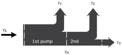
| Torque at 1st pump | T1 |
| Torque at 2nd pump | T2 |
| Torque at 3rd pump | T3 |
| Input torque | TE=T1+T2+T3 |
| TE < TE max | |
| Through-drive torque | TD=T2+T3 |
| TD < TD max |
1)Efficiency not considered
2) For drive shafts with no radial force
