Wenzhou Prance Hydraulic Equipment Co., Ltd.

-1.webp "A10VO63DFR1-53R(01) (1)")
-2.webp "A10VO63DFR1-53R(01) (2)")
-3.webp "A10VO63DFR1-53R(01) (3)")
-4.webp "A10VO63DFR1-53R(01) (4)")
-5.webp "A10VO63DFR1-53R(01) (5)")
-6.webp "A10VO63DFR1-53R(01) (6)")
Bomba hidráulica de desplazamiento variable personalizada A10VO serie 53
1. Bomba de caudal variable con grupo rotativo de pistones axiales en diseño de plato oscilante para transmisiones hidrostáticas en circuito abierto.
2.High permissible drive speed
3.Favorable power-to-weight ratio – compact dimensions
4.Excellent suction characteristics
5.Electro-hydraulic pressure control
6.Power control
Descripción detallada
This axial piston variable pump adopts a swashplate rotary group structure, professionally designed for open-circuit hydrostatic drive systems and suitable for various industrial hydraulic operation scenarios. It supports a high permissible drive speed, enabling efficient and high-speed operation of the whole equipment to meet high-frequency working demands. Featuring an optimized power-to-weight ratio, the pump boasts compact overall dimensions and lightweight construction, which facilitates flexible installation and equipment integration while saving layout space. It delivers excellent suction performance with low suction resistance and stable oil filling capacity, effectively preventing cavitation and air suction issues to ensure continuous and reliable hydraulic system operation. Equipped with electro-hydraulic pressure control and independent power control functions, the pump can precisely adjust system pressure and output power according to actual load changes, realizing stable operation, reasonable power matching and effective energy consumption reduction.
Selección y solicitud de cotización
Esta serie de productos debe seleccionarse en función del circuito hidráulico aprobado. Confirme el caudal o desplazamiento requerido, la presión continua y de punta, la velocidad de accionamiento, el tipo de control, el fluido y la interfaz de instalación antes de la selección final.
Información que debe incluir en su RFQ
- Desplazamiento o caudal requerido a la velocidad de operación
- Presión del sistema continua y máxima
- Velocidad de accionamiento, requisito de control y tipo de circuito
- Brida de montaje, eje, puertos, requisitos de fluido y filtración
Recursos relacionados
Datos técnicos
| Tamaño | NG | 10 | 18 | 28 | 45 | 60 | 63 | 72 | 85 | 100 | ||
| Desplazamiento geométrico por revolución | Vg máx | cm3 | 10.5 | 18 | 28 | 45 | 60 | 63 | 72 | 85 | 100 | |
| Velocidad de giro
máximo1) |
en VG máximo | nNombre | rpm | 3600 | 3300 | 3000 | 26004) | 2700 | 2600 | 2600 | 2500 | 2300 |
| en Vg <Vg máx 2) | nadm. máx. | rpm | 4320 | 3960 | 3600 | 3120 | 3140 | 3140 | 3140 | 3000 | 2500 | |
| Flujo | enNombre y VG máximo | qv | l/min | 37 | 59 | 84 | 117 | 162 | 163 | 187 | 212 | 230 |
| enE = 1500 rpm | qvE | l/min | 15 | 27 | 42 | 68 | 90 | 95 | 108 | 128 | 150 | |
| Poder | Con NNombre, VG máximo
y Δp = 250 bar |
P | kW | 16 | 25 | 35 | 49 | 65 | 68 | 77 | 89 | 96 |
| enE= 1500 rpm | PE | kW | 7 | 11 | 18 | 28 | 37 | 39 | 45 | 53 | 62 | |
| Par de torsión | en VG máximo
y Δp = 250 bar |
M | Nm | 42 | 71 | 111 | 179 | 238 | 250 | 286 | 338 | 398 |
| en VG máximo
y Δp = 100 bar |
M | Nm | 17 | 29 | 45 | 72 | 95 | 100 | 114 | 135 | 159 | |
| Rigidez torsional del eje de transmisión | S | c | Nm/rad | 9200 | 11000 | 22300 | 37500 | 65500 | 65500 | 65500 | 143000 | 143000 |
| R | c | Nm/rad | - | 14800 | 26300 | 41000 | 69400 | 69400 | 69400 | 152900 | 152900 | |
| U | c | Nm/rad | 6800 | 8000 | 16700 | 30000 | 49200 | 49200 | 49200 | 102900 | 102900 | |
| W | c | Nm/rad | - | - | 19900 | 34400 | 54000 | 54000 | 54000 | 117900 | 117900 | |
| P | c | Nm/rad | 10700 | - | - | - | - | - | - | - | - | |
| Moment of inertia of the rotary group | JTW | Kgm2 | 0.0006 | 0.0009 | 0.0017 | 0.003 | 0.0056 | 0.0056 | 0.0056 | 0.012 | 0.012 | |
| Aceleración angular máxima3) | α | rad/s2 | 8000 | 6800 | 5500 | 4000 | 3300 | 3300 | 3300 | 2700 | 2700 | |
| Volumen de casos | V | L | 0.2 | 0.25 | 0.3 | 0.5 | 0.8 | 0.8 | 0.8 | 1 | 1 | |
| Weight without through drive (approx.)
Weight with through drive (approx.) |
m | kg | 8 | 11.5 | 15 | 18 | 22 | 22 | 22 | 36 | 36 | |
| - | 13 | 18 | 24 | 28 | 28 | 28 | 45 | 45 | ||||
Determinación de las características de funcionamiento
| Flujo | qv=(Vg ∙ n ∙ ηv) / 1000 | l/min |
| Par de torsión | M=(Vg ∙ Δp) /(20 ∙ π ∙ ηhm) | Nm |
| Poder | P=(2π ∙ M ∙ n)/60000=(qv ∙ Δp)/(600 ∙ ηt) | kW |
Clave
Vg Cilindrada por revolución en [cm3]
Δp Presión diferencial [bar]
n Velocidad de giro [rpm]
ηv Eficiencia volumétrica
ηhm Rendimiento hidráulico-mecánico
ηt Eficiencia total (ηt= ηv*ηhm)
1) Los valores son aplicables:
- At an abs. pressure pabdominales = 1 bar at the suction port S
- for the optimum viscosity range from Velegir = 36 a 16 mm2/s
- with hydraulic fluid on the basis of mineral oils
2)See diagram on page 9 at speed increase up to nmax adm.
3)The data are valid for values between the minimum required and maximum permissible rotational speed. It applies for external stimuli (e.g. diesel engine 2 to 8 times rotary frequency, cardan shaft twice the rotary frequency). The limit value is only valid fora single pump. The load capacity of the connection parts must be considered.
Permissible radial and axial forces on the drive shaft
| Tamaño | NG | 10 | 18 | 28 | 45 | 60/63 | 72 | 85 | 100 | ||
| Maximum radial force at a/2 | 
radial force |
Fq max | N | 250 | 350 | 1200 | 1500 | 1700 | 1500 | 2000 | 2000 |
| Maximum axial force | 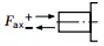
axial force |
±Fax max | N | 400 | 700 | 1000 | 1500 | 2000 | 1500 | 3000 | 3000 |
Permissible input and through-drive torques
| Tamaño | 10 | 18 | 28 | 45 | 60/63 | 72 | 85 | 100 | |||
| Torque at VG máximo y Δp = 250 bar1) | Mmáx | Nm | 42 | 71 | 111 | 179 | 250 | 321 | 338 | 398 | |
| Maximum input torque on drive shaft2) | |||||||||||
| S | ME max | Nm | 126 | 124 | 198 | 319 | 630 | 630 | 1157 | 1157 | |
| ∅ | in | 3/4 | 3/4 | 7/8 | 1 | 1 1/4 | 1 1/4 | 1 1/2 | 1 1/2 | ||
| R | ME max | Nm | - | 160 | 250 | 400 | 650 | 650 | 1215 | 1215 | |
| ∅ | in | - | 3/4 | 7/8 | 1 | 1 1/4 | 1 1/4 | 1 1/2 | 1 1/2 | ||
| U | ME max | Nm | 60 | 59 | 105 | 188 | 306 | 306 | 628 | 628 | |
| ∅ | in | 5/8 | 5/8 | 3/4 | 7/8 | 1 | 1 | 1 1/4 | 1 1/4 | ||
| W | ME max | Nm | - | - | 140 | 220 | 396 | 383 | 650 | 650 | |
| ∅ | in | - | - | 3/4 | 7/8 | 1 | 1 | 1 1/4 | 1 1/4 | ||
| P | ME max | Nm | 90 | - | - | - | - | - | - | - | |
| ∅ | mm | 18 | - | - | - | - | - | - | - | ||
| Maximum through-drive torque | |||||||||||
| S | MD max | Nm | - | 108 | 160 | 319 | 484 | 484 | 698 | 698 | |
| R | MD max | Nm | - | 120 | 176 | 365 | 484 | 484 | 698 | - | |
| U | MD max | Nm | - | 59 | 105 | 188 | 306 | 306 | 628 | 628 | |
| W | MD max | Nm | - | - | 140 | 220 | 396 | 383 | 650 | 650 | |
Distribution of torques
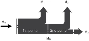
| Torque at 1st pump | M1 |
| Torque at 2nd pump | M2 |
| Torque at 3rd pump | M3 |
| Input torque | ME=M1+M2+M3 |
| ME < ME max | |
| Through∙drive torque | MD=M2+M3 |
| MD < MD max |
1)Efficiency not considered
2) For drive shafts with no radial force
