Wenzhou Prance Hydraulic Equipment Co., Ltd


CE Proportional Valve With Electronics 4WRPEH
1.4/4-way version
2.With control spool and sleeve in servo quality
3.Operated on one side, 4/4-fail-safe position in switched off state
4.Electric position feedback and integrated electronics (OBE), calibrated in the factory
5.Electrical connection 6P+PE; signal input differential amplifier with interface “A1” ± 10V or interface “F1” 4 … 20 mA (Rsh = 200 Ω)
6.Use for electro-hydraulic controls in production and testing systems
Detailed description
This valve is available in a 4/4-way version, which enables comprehensive control of hydraulic fluid direction and flow, supporting multi-directional actuation of hydraulic components and meeting the complex control needs of various hydraulic systems. It is equipped with a control spool and sleeve of servo quality, featuring high precision, tight fit, and excellent wear resistance, ensuring stable and accurate control performance even during long-term continuous operation. The valve is operated on one side, with a 4/4-fail-safe position when in the switched-off state; this design ensures that the valve automatically returns to a pre-set safe position in the event of power failure or signal interruption, preventing system damage and ensuring operational safety. It is equipped with electric position feedback and integrated electronics (OBE), which are factory-calibrated to ensure high control accuracy and consistent performance, eliminating the need for on-site calibration and simplifying commissioning. The electrical connection is 6P+PE, with a signal input differential amplifier that supports two interfaces: “A1” ± 10V or “F1” 4 … 20 mA (Rsh = 200 Ω), adapting to different control signal requirements. Additionally, the valve is specifically designed for electro-hydraulic controls in production and testing systems, where precise, stable, and reliable control is critical, making it suitable for a wide range of industrial production and testing scenarios.
Selection and RFQ
This valve series should be selected from the circuit function and approved control requirements. Confirm flow, pressure, spool or control function, electrical interface, mounting pattern and fluid cleanliness before final selection.
Information to include in your RFQ
- Required flow and working pressure
- Circuit function, spool or proportional-control requirement
- Electrical supply, command signal and feedback requirement where applicable
- Mounting pattern, port size, fluid and filtration class
Related resources
Ordering code
| 01 | 02 | 03 | 04 | 05 | 06 | 07 | 08 | 09 | 10 | 11 | 12 | 13 | 14 | |||
| 4 | WRP | E | H | 6 | B | - | 3X | / | / | 24 | * |
| 01 | 4 main ports | 4 |
| 02 | High-response valve, direct operated | WRP |
| 03 | With integrated electronics | E |
| 04 | Control spool/sleeve | H |
| 05 | Size 6 | 6 |
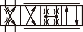
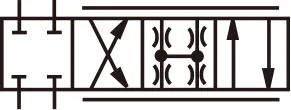
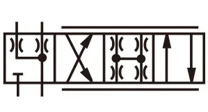
Control spool symbols
| 06 | Symbol | Flow characteristics L | Flow characteristics P | |
 |
||||
 |
● | ● | c | |
 |
● | ● | c1 1) | |
| ● | ● | c4 | ||
 |
● | ● | c3 | |
| ● | ● | c5 1) | ||
| 1) With symbols C1 and C5: P→A:qVnom B→T:qVnom/2 P→B:qVnom/2 A→T:qVnom qVnom 2:1 only with rated flow = 40 l/min |
||||
| 07 | Installation side of the inductive position transducer | B |
Rated flow of size 6 with 70 bar valve pressure differential (35 bar/control edge)
| Flow characteristics L | Flow characteristics P | |||
| 8 | 04 l/min | ● | ●(inflection at 40 %) | 04 |
| 12 l/min | ● | 12 | ||
| 15 l/min | ●(inflection at 60 %) | 15 | ||
| 24 l/min | ● | 24 | ||
| 25 l/min | ●(inflection at 60 %) | 25 | ||
| 40 l/min | ● | ●(inflection at 40 %) | 40 | |
●=Delivery range
Flow characteristics
| 09 | Linear | L |
| Inflected characteristic curve, linear | P |
| 10 | Component series 30 ... 39 (30 ... 39: Unchanged installation and connection dimensions) | 3X |
Seal material
| 11 | NBR seals | M |
| FKM seals | V |
| 12 | Supply voltage of the integrated electronics: 24 VDC | 24 |
Interfaces of the control electronics
| 13 | Command value input ± 10 V | A1 |
| Command value input 4 ... 20 mA | F1 |
| 14 | Further details in the plain text |
Technical data(For applications outside these parameters, please consult us!)
general
| Design | Spool valve, direct operated, with steel sleeve | |
| Actuation | Proportional solenoid with position control, OBE | |
| Type of connection | Subplate mounting, porting pattern according to ISO 4401 | |
| Installation position | Any | |
| Ambient temperature range | ℃ | -20 ...+60 |
| Storage temperature range with UV protection | ℃ | +10...+40 |
| Transport temperature | ℃ | -30...+80 |
| Sine test according to DIN EN 60068-2-6 | 10...2000 Hz / maximum of 10 g/ 10 cycles/3 axes | |
| Noise test according to DIN EN 60068-2-64 | 20...2000 Hz / 10 gRMS / 30 g peak / 30 min /3 axes | |
| Transport shock according to DIN EN 60068-2-27 | 15g/11 ms/3 axes | |
| Weight | kg | 2.9 |
| Maximum relative humidity (no condensation) | % | 95 |
| Maximum solenoid surface temperature | ℃ | 150 |
| MTTFd value according to EN ISO 13849 | Yaers | 150 (for further details see data sheet 08012) |
Hydraulic
| Hydraulic fluid | See table on page 6 | ||||||
| Viscosity range | -recommended | mm2/s | 20...100 | ||||
| -maximum admissible | mm2/s | 10...800 | |||||
| Hydraulic fluid temperature range (flown-through) | ℃ | -20 ...+70 | |||||
| Maximum admissible degree of contamination of the hydraulic fluid,cleanliness class according to ISO 4406 (c) | Class 18/16/131) | ||||||
| Rated flow at Δp = 35 bar per edge 2) | l/min | 4 | 12 | 15 | 24/25 | 40 | |
| Maximum operating pressure |
- Ports A, B, P | bar | 350 | ||||
| -Port T | bar | 250 | |||||
| Limitation of use withregard to the transitionto failsafe(values apply to sum-mated edge) | - Spool symbols C3, C5, C | bar | 350 | 350 | 350 | 350 | 160 |
| -Spool symbols C1, C4 | bar | 350 | 350 | 280 | 250 | 100 | |
| Leakage flow at 100 bar | -Linear characteristic curve L | cm3/min | < 180 | < 300 | - | < 500 | < 900 |
| -Inflected characteristic curve P | cm3/min | < 150 | - | < 180 | < 300 | < 450 | |
static/dynamic
| Hysteresis | % | < 0.1 |
| Range of inversion | % | < 0.05 |
| Response sensitivity | % | < 0.05 |
| Manufacturing tolerance qVmax | % | < 10 |
| Temperature drift (temperature range 20℃ ... 80 ℃) | Zero shift < 0.25 % with Δ∂= 10 K | |
| Pressure drift | % 100 bar | Zero shift < 0.15 |
| Zero compensation | Ex factory ±1 % |
1) The cleanliness classes specified for the components must be adhered to in hydraulic systems. Effective filtration prevents faults and at the same time increases the life cycle of the components.
2)Flow with different Δp:qx=qνnom·√(Δpx/35)
| Hydraulic fluid | Classification | Suitable sealing materials |
Standards | |
| Mineral oils and related hydrocarbons | HL, HLP, HLPD, HVLP, HVLPD | NBR,FKM | DIN 51524 | |
| Bio-degradable | -insoluble in water | HETG | NBR,FKM | ISO 15380 |
| HEES | FKM | |||
| -soluble in water | HEPG | FKM | ISO 15380 | |
| Flame-resistant | -water-free | HFDU, HFDR | FKM | ISO 12922 |
| -containing water | HFC (Fuchs HYDROTHERM 46M, Petrofer Ultra Safe 620) |
NBR | ISO 12922 | |
| Important information on hydraulic fluids! ▶There may be limitations regarding the technical valve data (temperature, pressure range, life cycle, maintenance intervals, etc.)! ▶The flash point of the hydraulic fluid used must be 40 K higher than the maximum solenoid surface temperature. ▶Mineral oils and related hydrocarbons: - If mineral oils and related hydrocarbons are used,data sheet 90220 must be complied with! ▶Bio-degradable: - If bio-degradable hydraulic fluids are used, data sheet 90221 must be complied with! ▶Flame-resistant - water-free: - If flame-resistant, water-free hydraulic fluids are used, datasheet 90222 must be complied with! ▶Flame-resistant - containing water: The maximum pressure differential per control edge is 50 bar. Pressure pre-loading atthe tank port > 20 % of the pressure differential; otherwise,increased cavitation. Life cycle as compared to operation with mineral oil HL, HLP 50 % to 100 %. |
||||
electrical, integrated electronics (OBE)
| Relative duty cycle (%) | 100 (continuous operation) |
| Protection class according to EN 60529 | IP 65 with mounted and locked plug-in connectors |
| Supply voltage Terminal A: Terminal B: Maximum admissible residual ripple |
24 V= At least 19 V=/maximum 36 V= 0V 2.5 Vpp |
| Maximum power consumption | 40 VA |
| Fuse protection, external | 2.5AT |
| Input, version A1 Terminal D: UE Terminal E: |
Differential amplifier, Ri = 100 kΩ 0...±10V 0V |
| Input, version F1 Terminal D: ID-E Terminal E: ID-E |
Load, Rsh = 200 Ω 4 ... (12) ... 20 mA Current loop ID-E feedback |
| Maximum voltage of the differential inputs against 0 V |
|
| Test signal, version A1 Terminal F: Utest Terminal C: |
LVDT 0...±10V Reference 0 V |
| Test signal, version F1 Terminal F: IF-C Terminal C: IF-C |
LVDT signal 4 ... 20 mA at external load 200 ... 500 Ω maximum 4 ... 20 mA output Current loop IF-C feedback |
| Functional earth and screening | See pin assignment (CE-compliant installation) |
| Adjustment | Calibrated in the factory, see valve characteristic curve |
| Conformity | CE according to EMC Directive 2004/108/EC Tested according to EN 61000-6-2 and EN 61000-6-3 |
