شركة ونزهو برانس للمعدات الهيدروليكية المحدودة


A10VO Series 32 Variable Piston Pump
The A10VO Series 32 variable pump is offered with ISO mounting, SAE metric flange connections and two case-drain ports. Its model series and control suffix must be preserved when checking a replacement against another A10VO generation.
- Series 32 pump identification
- ISO mounting reference
- SAE metric flange connections
- Two case-drain ports
PRANCE HYDRAULIC · PRODUCT SERIES
A10VO Series 32 Variable Piston Pump
Axial piston; variable swashplate · Open circuit
The A10VO Series 32 variable pump is offered with ISO mounting, SAE metric flange connections and two case-drain ports. Its model series and control suffix must be preserved when checking a replacement against another A10VO generation.
Model
✓
Request a Quotationعرض البيانات الفنية وورقة البياناتA10VO Series 32Axial piston; variable swashplate
Confirm the complete model and approved specification with Prance Hydraulic. Product-series references alone do not establish interchangeability.
Configuration review · Technical documentation · Product selection
تفاصيل المنتج
- Series 32 pump identification
- ISO mounting reference
- SAE metric flange connections
- Two case-drain ports
CATEGORIES: مضخة مكبسية, مضخة ذات إزاحة متغيرة
A10VO Series 32 Features & Application
Series 32 pump identification
Include the series and all order-code suffixes in the enquiry. A common nominal size does not establish compatibility.
ISO mounting reference
Check pilot diameter, bolt pattern, shaft engagement or port pattern against the approved installation drawing.
SAE metric flange connections
Check pilot diameter, bolt pattern, shaft engagement or port pattern against the approved installation drawing.
Two case-drain ports
Specify the full A17FO Series 10 order code, installation drawing and operating duty so the quotation can identify the proposed configuration.
A10VO Series 32 Specifications
| Series / model | A10VO Series 32 |
|---|---|
| Product type | A10VO Series 32 Variable Piston Pump |
| تصميم | Axial piston; variable swashplate |
| Circuit / selection | Open circuit |
| Published nominal sizes | 45, 71, 100, 140 and 180 |
| Listed maximum geometric displacement | 45, 71.1, 100, 140 and 180 cm³/rev |
A10VO Series 32 Selection & Configuration
The A10VO Series 32 variable pump is offered with ISO mounting, SAE metric flange connections and two case-drain ports. Its model series and control suffix must be preserved when checking a replacement against another A10VO generation.
Identify the required mounting, shaft and port orientation using the drawing, then choose the drain port appropriate to the installation. Match the control function and operating point to the Series 32 data rather than reusing Series 31 settings without review.

Your Application.
The Right Configuration.
Hydraulic pumps · Hydraulic motors · Hydraulic valves
Send the A17FO Series 10 nameplate, operating requirements and installation drawing for a configuration review before quoting.
- Model review — send the full model code or an existing nameplate photograph.
- Interface matching — confirm shaft, mounting flange, rotation and ports.
- Operating conditions — provide flow, pressure, speed, fluid and duty cycle.
- Documentation — request the relevant product data and drawings for your review.

A10VO Series 32 Buying Guide
Use this sequence to prepare the A10VO Series 53 configuration for review and quotation.
- Define required flow at the actual drive speed and continuous pressure.
- Identify peak pressure, duration and the work cycle.
- Confirm the selected displacement control and any auxiliary-drive requirement.
- Match rotation viewed from the shaft end, shaft, flange and ports.
- Review inlet conditions, drain routing and the installation envelope.
- Confirm fluid, viscosity, temperature, filtration and seals.
- Approve the complete model, control, drawing, quantity and delivery terms.

Selection, Documentation & Project Support

Selection Support
Learn more →Share your hydraulic circuit, operating point and installation requirements for a configuration discussion.
Flow · Pressure · Speed · Interfaces

Technical Resources
Learn more →Review product documentation, model codes and technical data before finalizing the specification.
Datasheets · Model codes · Drawings

Project Inquiries
Learn more →Send your required model, quantity, application and project requirements to discuss your inquiry.
Product inquiries · Configuration review
Configuration, Quantity & Delivery
Confirm the complete A17FO Series 10 code, approved drawing and operating limits. Availability, quantity, documentation and delivery date are confirmed in the quotation.
Discuss Your A10VO Series 32 Application
Send the full model code, operating duty, installation details and quantity.
Request a A10VO Series 32 QuotationA10VO Series 32 Questions Before Ordering
What type of product is the A10VO Series 32?
A10VO Series 32 Variable Piston Pump. Design: Axial piston; variable swashplate. Open circuit. Confirm the complete order code for the offered version.
Can a similar pump replace the A10VO Series 32?
cURL Too many subrequests by single Worker invocation. To configure this limit, refer to https://developers.cloudflare.com/workers/wrangler/configuration/#limits.
cURL Too many subrequests by single Worker invocation. To configure this limit, refer to https://developers.cloudflare.com/workers/wrangler/configuration/#limits
Define required flow at the actual drive speed and continuous pressure. Identify peak pressure, duration and the work cycle. Attach the nameplate, complete order code, installation drawing and required quantity.
A10VO Series 32 Technical Data & Documents
View A10VO Series 32 catalog data and operating conditions
cURL Too many subrequests by single Worker invocation. To configure this limit, refer to https://developers.cloudflare.com/workers/wrangler/configuration/#limits.
البيانات الفنية
| حجم | غير مقبول | 045 | 071 | 100 | 140 | 180 | |||
| الإزاحة الهندسية لكل دورة | Vجي ماكس | سم3 | 45 | 71.1 | 100 | 140 | 180 | ||
| Maximum rotational speed1)2) | at | Vجي ماكس | nالاسمية | دورة في الدقيقة | 3000 | 2550 | 2300 | 2200 | 1800 |
| عزم الدوران | at | Vجي ماكس and Δp = 280 bar | T | لا شيء جديد | 200 | 317 | 446 | 624 | 802 |
| at | Vجي ماكس و Δp = 100 بار | T | لا شيء جديد | 72 | 113 | 159 | 223 | 286 | |
| Rotary stiffness ofdrive shaft | S | c | نيوتن متر/راديان | 37500 | 71884 | 121142 | 169537 | 171107 | |
| R | c | نيوتن متر/راديان | 41025 | 76545 | – | – | – | ||
| U | c | نيوتن متر/راديان | 30077 | 52779 | 91093 | on | – | ||
| request | |||||||||
| W | c | نيوتن متر/راديان | 34463 | 57460 | 101847 | 165594 | – | ||
| عزم القصور الذاتي للمجموعة الدوارة | JTW | كجم.م2 | 0.0035 | 0.0087 | 0.0167 | 0.0242 | 0.033 | ||
| التسارع الزاوي الأقصى3) | α | راديان/ثانية2 | 4000 | 2900 | 2400 | 2000 | 2000 | ||
| حجم الحالة | V | L | 1.0 | 1.6 | 2.2 | 3.0 | 2.7 | ||
| Weight (11N00 and 12N00 without through drive) approx. | m | kg | 25.8 | 40.4 | 56.4 | 70.5 | 75.2 | ||
| Weight (12Kxx) approx. | m | kg | 27.4 | 43.3 | 62.6 | 79.5 | – | ||
| Weight (22Uxx/32Uxx)approx. | m | kg | 32.6 | 51.8 | 76 | 90.2 | 89.4 | ||
تحديد خصائص التشغيل
مفتاح
Vg الإزاحة لكل دورة في [سم3] Δp Differential pressure [bar] n Rotational speed [rpm] ηv Volumetric efficiency ηمم Hydraulic-mechanical efficiency ηt الكفاءة الكلية (ηt= ηv*ηhm)ملاحظة
▶Theoretical values, without efficiency and tolerances;values rounded ▶Operation above the maximum values or below the minimum values may result in a loss of function,a reduced service life or in the destruction of the axial piston unit. Prance recommends testing the loads by means of experiment or calculation /simulation and comparison with the permissible values. 1) The values are applicable: – to the optimum viscosity range from Vاختيار = 36 إلى 16 ملم2/s – to hydraulic fluid based on mineral oils 2) The values apply at absolute pressure pabs = 1.0 bar at suction port S. 3)4)The data are valid for values between the minimum required and maximum permissible rotational speed. Valid for external excitation(e.g. diesel engine 2 to 8 times rotary frequency; cardan shaft twice the rotary frequency). The limit value is only valid for a single pump. The load capacity of the connecting parts must be considered.القوى الشعاعية والمحورية المسموح بها على عمود القيادة
| حجم | غير مقبول | 45 | 71 | 100 | 140 | 180 | ||
| أقصى قوة شعاعية عند a/2 |  |
Fq الحد الأقصى | N | 1500 | 1900 | 2300 | 2800 | 2300 |
| القوة المحورية القصوى |  |
±Fax max | N | 1500 | 2400 | 4000 | 4800 | 800 |
ملاحظة
▶For drives with radial loading (pinion, V-belt), please contact us! ▶The values given are maximum values and do not apply to continuous operation.عزم الإدخال والعزم المسموح بهما للقيادة عبر
| حجم | 45 | 71 | 100 | 140 | 180 | |||
| Input torque at drive shaft, maximum2) | ||||||||
| S | TE max | لا شيء جديد | 319 | 626 | 1104 | 1620 | 1834 | |
| ∅ | in | 1 | 1 1/4 | 1 1/2 | 1 3/4 | 1 3/4 | ||
| R | TE max | لا شيء جديد | 400 | 644 | – | – | – | |
| ∅ | in | 1 | 1 1/4 | – | – | – | ||
| U | TE max | لا شيء جديد | 188 | 300 | 595 | on request | – | |
| ∅ | in | 7/8 | 1 | 1 1/4 | 1 1/2 | – | ||
| W | TE max | لا شيء جديد | – | 394 | 636 | 1220 | 1488 | |
| ∅ | in | – | 1 | 1 1/4 | 1 1/2 | 1 1/2 | ||
| عزم الدوران المسموح به عبر القيادة القصوى | ||||||||
| S | TD max | لا شيء جديد | 319 | 492 | 778 | 1266 | 1266 | |
| R | TD max | لا شيء جديد | 365 | 548 | – | – | – | |
| U | TD max | لا شيء جديد | 188 | – | 595 | on request | – | |
| W | TD max | لا شيء جديد | – | – | 636 | 1220 | 1266 | |
توزيع عزم الدوران
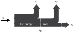
| عزم الدوران الإدخالي | TE=T1+T2+T3 |
| TE < TE max | |
| عزم الدوران عبر القيادة | TD=T2+T3 |
| TD < TD max |
Watch A10VO Series 32 Product Video
Related Selection Resources
Request a A10VO Series 32 Quotation
أخبرنا بالتكوين المطلوب، الكمية والتطبيق.
المنتجات ذات الصلة
Compare related hydraulic pumps and confirm the complete configuration for your application.


رمز الطلب
| 01 | 02 | 03 | 04 | 05 | 06 | 07 | 08 | 09 | 10 | 11 | 12 | ||
| A10V | ○ | / | 32 | - | v |
وحدة كباس محوري
| 01 | تصميم الصفيحة المائلة، متغير، الضغط الاسمي 280 بار، أقصى ضغط 350 بار | A10V |
وضع التشغيل
| 02 | مضخة، الدائرة المفتوحة | ○ |
الحجم (نيجيريا)
| 03 | الازاحة الهندسية، انظر "البيانات الفنية" في الصفحة 7 | 045 | 071 | 100 | 140 | 180 |
أجهزة التحكم
| 04 | منظم الضغط | هيدروليكي | ● | ● | ● | ● | ● | دكتور | |||
| مع وحدة تحكم التدفق | هيدروليكي | إكس - تي مفتوح | ● | ● | ● | ● | ● | دي آر إف | |||
| تم توصيل X-T | مع وظيفة الشطف | ● | ● | ● | ● | ● | نظام تقليل المقاومة | ||||
| تم توصيل X-T | بدون وظيفة التنظيف | ● | ● | ● | ● | ● | DRSC | ||||
| قطع الضغط | هيدروليكي | تحكم عن بعد | ● | ● | ● | ● | ● | دي إر جي | |||
| كهربائي | تحكم سلبي | الجهد = 12 فولت | ● | ● | ● | ● | ● | ED71 | |||
| الجهد = 24 فولت | ● | ● | ● | ● | ● | ED72 | |||||
| كهربائي | شاهد إيجابي | الجهد = 12 فولت | ● | ● | ● | ● | ● | ER711) | |||
| الجهد = 24 فولت | ● | ● | ● | ● | ● | ER722) | |||||
| ضغط تفاضلي
سيطرة |
كهربائي | تحكم سلبي | راجع ورقة البيانات 92709 | ● | ● | ● | ● | ○ | إي إف. | ||
| وحدة تحكم بالطاقة مع | |||||||||||
| قطع الضغط | هيدروليكي | بداية التحكم | إلى | ٥٠ بار | ● | ● | ● | ● | ● | LA5D | |
| من | من 51 إلى 90 بار | ● | ● | ● | ● | ● | LA6D | ||||
| من 91 إلى 160 بار | ● | ● | ● | ● | ● | لاحظ | |||||
| من 161 إلى 240 بار | ● | ● | ● | ● | ● | LA8D | |||||
| فوق | ٢٤٠ بار | ● | ● | ● | ● | ● | لاقد | ||||
| قطع الضغط والتحكم في التدفق | هيدروليكي | بداية التحكم | راجع LA.D | ● | ● | ● | ● | ● | لوس أنجلوس | ||
| تحكم عن بعد
قطع الضغط |
هيدروليكي | بداية التحكم | راجع LA.D | ● | ● | ● | ● | ● | لوس أنجلوس.دي جي | ||
| فصل التحكم في التدفق | هيدروليكي | بداية التحكم | راجع LA.D | ● | ● | ● | ● | ● | LA.S | ||
مسلسل
| 05 | المسلسل 3، الفهرس 2 | 32 |
اتجاه الدوران
| 06 | تمت معاينته على عمود الدوران | مع عقارب الساعة | R |
| عكس عقارب الساعة | L |
ختم
| 07 | FKM (إيلاستومر فلوري) | V |
عمود الدوران
| 08 | عمود مسنن
ANSI B92.1a |
عمود قياسي | ● | ● | ● | ● | ● | S |
| مشابه للعمود "S" ولكن لعزم دوران أدخل أعلى | ● | ● | - | - | - | R | ||
| قطر مخفض، ملاءمة محدودة للتشغيل النافذ | ● | ● | ● | ● | - | U | ||
| مثل العمود "U"، ولكن لعزم دوران أعلى، ومناسبية محدودة للتشغيل النافذ | - | - | ● | ● | ● | W |
شفة التركيب
| 045 | 071 | 100 | 140 | 180 | 045 | |||
| 09 | آي إس أو 3019-1 (إس إيه إي) | SAE C؛ فتحتان | ● | ● | ● | ● | - | C |
| SAE C؛ 4 فتحات | ● | ● | ● | ● | ● | D | ||
| SAE D؛ 4 فتحات | - | ● | - | - | - | U |
منفذ عامل
| 10 | منفذ شفة SAE (لوحات المنافذ وتخصيص الدفع النافذ،,
انظر إلى الموضع 11 |
لولب تثبيت متري خلفي (ليس للتشغيل النافذ) | ● | ● | ● | ● | ● | 11 |
| في الأعلى، في الأسفل، على الجانب المقابل، سن ربط متري | ● | ● | ● | ● | - | 12 | ||
| في الأعلى، في الأسفل، على الجانب المقابل، سن ربط متري مع فتحة تمرير شاملة U..؛ بدون مخمد نبضات | ○ | ○ | ○ | ○ | ● | 221) | ||
| في الأعلى، في الأسفل، على الجانب المقابل، سن ربط متري مع تجويف تمرير شامل U..؛ مع مخمد للنبضات | ○ | ○ | ○ | ○ | ● | 321) |
من خلال القيادة
| 11 | شفة ISO 3019-1
قطر |
أرفق
أنا4) |
سرّة لعمود مسنن2)
قطر |
|||||||
| 045 | 071 | 100 | 140 | 180 | ||||||
| بدون محرك مرور | (فقط للوحات المنافذ 11 و 12) | ● | ● | ● | ● | ● | N00 | |||
| ٢-٨٢ (أ) |  |
٥/٨ بوصة | 9T 16/32DP | ● | ● | ● | ● | - | K01 | |
| ٣/٤ بوصة | 11 سن 16/32DP | ● | ● | ● | ● | - | K52 | |||
| ١٠١-٢ (ب) | |
7/8 بوصة | 13 سن 16/32DP | ● | ● | ● | ● | - | K68 | |
| ١ بوصة | 15T 16/32DP | ● | ● | ● | ● | - | K04 | |||
| 127-2 (C) |  |
١ وربع بوصة | 14 سن 12/24 دي بي | - | ● | ● | ● | - | K07 | |
| 1 1/2 بوصة | 17T12/24DP | - | - | ● | ● | - | K24 | |||
| 127-4 (C) |  |
١ ١/٤ بوصة | 14 سن 12/24 دي بي | - | ○ | ● | ● | - | K15 | |
| 152-4 (D) | |
١ ٣/٤ بوصة | 13 سن 8/16DP | - | - | - | ● | - | K17 | |
| بدون محرك مرور | (ممكن فقط مع لوحات المنافذ 22 و 32)3) | ○ | ○ | ○ | ○ | ● | U00 | |||
| ٢-٨٢ (أ) | |
٥/٨ بوصة | 9T 16/32DP | ○ | ○ | ○ | ○ | ● | U01 | |
| ٣/٤ بوصة | 13 سن 16/32DP | ○ | ○ | ○ | ○ | ● | U52 | |||
| 101-2(ب) | |
7/8 بوصة | 13 سن 16/32DP | ○ | ○ | ○ | ○ | ● | U68 | |
| ١ بوصة | 15T 16/32DP | ○ | ○ | ○ | ○ | ● | U04 | |||
| 127-2 (C) | |
١ وربع بوصة | 14 سن 12/24 دي بي | - | ○ | ○ | ○ | ● | U07 | |
| 1 1/2 بوصة | 17 سن 12/24DP | - | - | ○ | ○ | ● | ي 24 | |||
| 127-4 (C) | |
واحد في | 15T 16/32DP | ○ | ○ | ○ | ○ | ○ | الاتحاد الأوروبي 2 | |
| ١ ١/٤ بوصة | 14 سن 12/24 دي بي | - | - | ○ | ○ | ● | تحت 15 | |||
| 152-4 (D) | |
١ ٣/٤ بوصة | 13 سن 8/16DP | - | - | - | ○ | ● | تحت 17 سنة | |
موصلات الملفات اللولبية5)
| 12 | بدون موصل (بدون ملف لولبي، بالتحكم الهيدروليكي فقط، بدون رمز) | |
| موصل ديوتش مصبوب، ذو طرفين - بدون ديود مانع للتشويش | P |
•=متوفر ○=عند الطلب -=غير متوفر
ملاحظات
لاحظ ملاحظات التخطيط للمشروع في الصفحة 54!
بالإضافة إلى رمز النوع، يرجى تحديد البيانات الفنية ذات الصلة عند تقديم طلبك.
1)فقط مع شفة التثبيت (موضع رمز الطلب 09) D أو U
2)وفقاً للمعيار ANSI B92.1a (أعمدة مسننة وفقاً لـ SAE J744)
3)مع عمود إدارة نافذ، بدون سرة، بدون شفة وسيطة، مغلق على أساس موثوق وظيفياً بغطاء. لمجموعات التثبيت، انظر ورقة البيانات 95581.
4)نمط الثقوب النافذة للتركيب يُنظر إليه من جهة محرك التدوير مع وجود وحدة التحكم في الأعلى.
5)قد تختلف موصلات المكونات الكهربائية الأخرى.
البيانات الفنية
| حجم | غير مقبول | 045 | 071 | 100 | 140 | 180 | |||
| الإزاحة الهندسية لكل دورة | Vجي ماكس | سم3 | 45 | 71.1 | 100 | 140 | 180 | ||
| Maximum rotational speed1)2) | at | Vجي ماكس | nالاسمية | دورة في الدقيقة | 3000 | 2550 | 2300 | 2200 | 1800 |
| تدفق | at | nالاسمية و Vجي ماكس | qv | لتر/دقيقة | 135 | 181 | 230 | 308 | 324 |
| طاقة | at | nالاسمية, Vجي ماكس and Δp = 280 bar | P | كيلوواط | 63 | 85 | 107 | 144 | 151 |
| عزم الدوران | at | Vجي ماكس and Δp = 280 bar | T | لا شيء جديد | 200 | 317 | 446 | 624 | 802 |
| at | Vجي ماكس و Δp = 100 بار | T | لا شيء جديد | 72 | 113 | 159 | 223 | 286 | |
| Rotary stiffness ofdrive shaft | S | c | نيوتن متر/راديان | 37500 | 71884 | 121142 | 169537 | 171107 | |
| R | c | نيوتن متر/راديان | 41025 | 76545 | - | - | - | ||
| U | c | نيوتن متر/راديان | 30077 | 52779 | 91093 | on | - | ||
| request | |||||||||
| W | c | نيوتن متر/راديان | 34463 | 57460 | 101847 | 165594 | - | ||
| عزم القصور الذاتي للمجموعة الدوارة | JTW | كجم.م2 | 0.0035 | 0.0087 | 0.0167 | 0.0242 | 0.033 | ||
| التسارع الزاوي الأقصى3) | α | راديان/ثانية2 | 4000 | 2900 | 2400 | 2000 | 2000 | ||
| حجم الحالة | V | L | 1.0 | 1.6 | 2.2 | 3.0 | 2.7 | ||
| Weight (11N00 and 12N00 without through drive) approx. | m | kg | 25.8 | 40.4 | 56.4 | 70.5 | 75.2 | ||
| Weight (12Kxx) approx. | m | kg | 27.4 | 43.3 | 62.6 | 79.5 | - | ||
| Weight (22Uxx/32Uxx)approx. | m | kg | 32.6 | 51.8 | 76 | 90.2 | 89.4 | ||
تحديد خصائص التشغيل
| تدفق | qv=(Vg ∙ n ∙ ηv) / 1000 | لتر/دقيقة |
| عزم الدوران | T=(Vg ∙ Δp) / 20 ∙ π ∙ ηمم | لا شيء جديد |
| طاقة | P=(2π ∙ T ∙ n)/60000=(qv ∙ Δp)/600 ∙ ηt | كيلوواط |
مفتاح
Vg الإزاحة لكل دورة في [سم3]
Δp ضغط تفاضلي [بار]
ن سرعة الدوران [دورة في الدقيقة]
ηv الكفاءة الحجمية
ηمم الكفاءة الهيدروليكية الميكانيكية
ηt الكفاءة الكلية (ηt= ηv*ηhm)
ملاحظة
▶القيم النظرية، بدون الكفاءة والتحملات؛ القيم مقربة
▶Operation above the maximum values or below the minimum values may result in a loss of function, a reduced service life or in the destruction of the axial piston unit. Bosch Rexroth recommend testing the load by means of experiment or calculation/simulation and comparison with the permissible values.
1) القيم قابلة للتطبيق:
- to the optimum viscosity range from Vاختيار = 36 إلى 16 ملم2/s
- to hydraulic fluid based on mineral oils
2) The values apply at absolute pressure pabs = 1.0 bar at suction port S.
3)4)The data are valid for values between the minimum required and maximum permissible rotational speed. Valid for external excitation(e.g. diesel engine 2 to 8 times rotary frequency; cardan shaft twice the rotary frequency). The limit value is only valid for a single pump. The load capacity of the connecting parts must be considered.
القوى الشعاعية والمحورية المسموح بها على عمود القيادة
| حجم | غير مقبول | 45 | 71 | 100 | 140 | 180 | ||
| أقصى قوة شعاعية عند a/2 | |
Fq الحد الأقصى | N | 1500 | 1900 | 2300 | 2800 | 2300 |
| القوة المحورية القصوى | |
±Fax max | N | 1500 | 2400 | 4000 | 4800 | 800 |
ملاحظة
▶For drives with radial loading (pinion, V-belt), please contact us!
The values given are maximum values and do not apply to continuous operation
عزم الإدخال والعزم المسموح بهما للقيادة عبر
| حجم | 45 | 71 | 100 | 140 | 180 | |||
| عزم الدوران عند Vجي ماكس and Δp = 280 bar1) | Tالحد الأقصى | لا شيء جديد | 200 | 316 | 446 | 624 | 802 | |
| Input torque at drive shaft, maximum2) | ||||||||
| S | TE max | لا شيء جديد | 319 | 626 | 1104 | 1620 | 1834 | |
| ∅ | in | 1 | 1 1/4 | 1 1/2 | 1 3/4 | 1 3/4 | ||
| R | TE max | لا شيء جديد | 400 | 644 | - | - | - | |
| ∅ | in | 1 | 1 1/4 | - | - | - | ||
| U | TE max | لا شيء جديد | 188 | 300 | 595 | on
request |
- | |
| ∅ | in | 7/8 | 1 | 1 1/4 | 1 1/2 | - | ||
| W | TE max | لا شيء جديد | - | 394 | 636 | 1220 | 1488 | |
| ∅ | in | - | 1 | 1 1/4 | 1 1/2 | 1 1/2 | ||
| عزم الدوران المسموح به عبر القيادة القصوى | ||||||||
| S | TD max | لا شيء جديد | 319 | 492 | 778 | 1266 | 1266 | |
| R | TD max | لا شيء جديد | 365 | 548 | - | - | - | |
| U | TD max | لا شيء جديد | 188 | - | 595 | on
request |
- | |
| W | TD max | لا شيء جديد | - | - | 636 | 1220 | 1266 | |
توزيع عزم الدوران
| عزم الدوران عند المضخة الأولى | T1 |
| عزم الدوران عند المضخة الثانية | T2 |
| عزم الدوران عند المضخة الثالثة | T3 |
| عزم الدوران الإدخالي | TE=T1+T2+T3 |
| TE < TE max | |
| عزم الدوران عبر القيادة | TD=T2+T3 |
| TD < TD max |
1)الكفاءة غير محسوبة
2) لأعمدة القيادة بدون قوة شعاعية
