Wenzhou Prance Hydraulic Equipment Co., Ltd


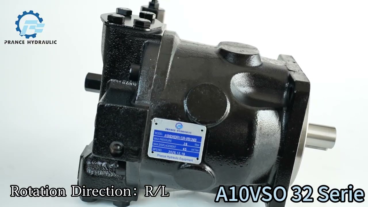
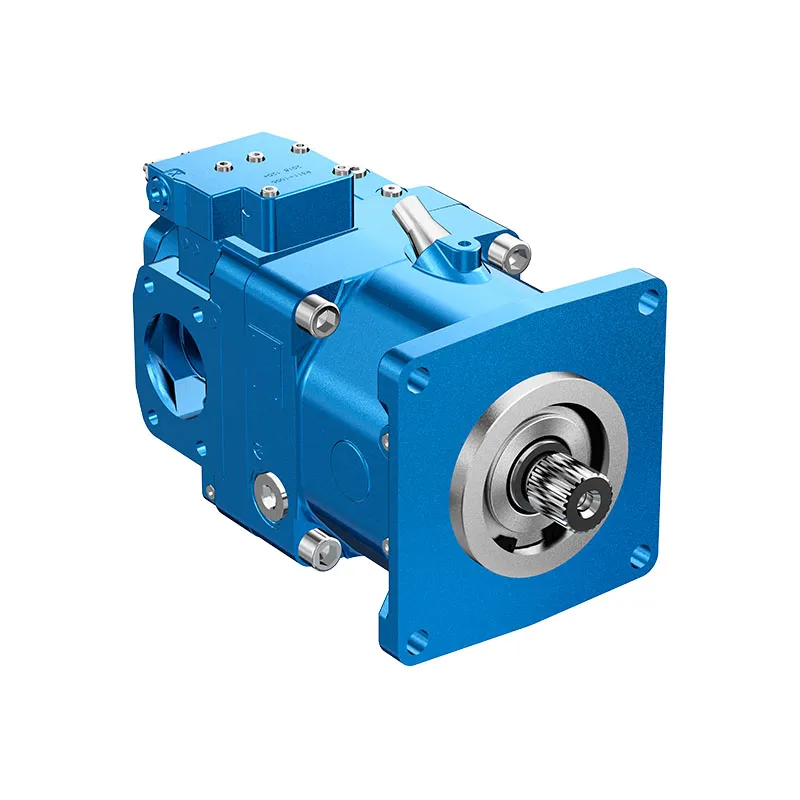
A10VO Series 32 Variable Piston Pump
The A10VO Series 32 variable pump is offered with ISO mounting, SAE metric flange connections and two case-drain ports. Its model series and control suffix must be preserved when checking a replacement against another A10VO generation.
- Series 32 pump identification
- ISO mounting reference
- SAE metric flange connections
- Two case-drain ports
PRANCE HYDRAULIC · PRODUCT SERIES
A10VO Series 32 Variable Piston Pump
Axial piston; variable swashplate · Open circuit
The A10VO Series 32 variable pump is offered with ISO mounting, SAE metric flange connections and two case-drain ports. Its model series and control suffix must be preserved when checking a replacement against another A10VO generation.
Modèle
✓
Demander un devisVoir les données techniques et la fiche techniqueA10VO Series 32Axial piston; variable swashplate
Confirm the complete model and approved specification with Prance Hydraulic. Product-series references alone do not establish interchangeability.
Étude de configuration · Documentation technique · Sélection de produits
Détails du produit
- Series 32 pump identification
- ISO mounting reference
- SAE metric flange connections
- Two case-drain ports
CATÉGORIES : Pompe à piston, Pompe à cylindrée variable
A10VO Series 32 Features & Application
Series 32 pump identification
Include the series and all order-code suffixes in the enquiry. A common nominal size does not establish compatibility.
ISO mounting reference
Check pilot diameter, bolt pattern, shaft engagement or port pattern against the approved installation drawing.
SAE metric flange connections
Check pilot diameter, bolt pattern, shaft engagement or port pattern against the approved installation drawing.
Two case-drain ports
Specify the full A17FO Series 10 order code, installation drawing and operating duty so the quotation can identify the proposed configuration.
A10VO Series 32 Specifications
| Series / model | A10VO Series 32 |
|---|---|
| Product type | A10VO Series 32 Variable Piston Pump |
| Conception | Axial piston; variable swashplate |
| Circuit / selection | Circuit ouvert |
| Published nominal sizes | 45, 71, 100, 140 and 180 |
| Listed maximum geometric displacement | 45, 71.1, 100, 140 and 180 cm³/rev |
A10VO Series 32 Selection & Configuration
The A10VO Series 32 variable pump is offered with ISO mounting, SAE metric flange connections and two case-drain ports. Its model series and control suffix must be preserved when checking a replacement against another A10VO generation.
Identify the required mounting, shaft and port orientation using the drawing, then choose the drain port appropriate to the installation. Match the control function and operating point to the Series 32 data rather than reusing Series 31 settings without review.

Your Application.
The Right Configuration.
Hydraulic pumps · Hydraulic motors · Hydraulic valves
Send the A17FO Series 10 nameplate, operating requirements and installation drawing for a configuration review before quoting.
- Model review — send the full model code or an existing nameplate photograph.
- Interface matching — confirm shaft, mounting flange, rotation and ports.
- Operating conditions — provide flow, pressure, speed, fluid and duty cycle.
- Documentation — request the relevant product data and drawings for your review.

A10VO Series 32 Buying Guide
Use this sequence to prepare the A10VO Series 53 configuration for review and quotation.
- Define required flow at the actual drive speed and continuous pressure.
- Identify peak pressure, duration and the work cycle.
- Confirm the selected displacement control and any auxiliary-drive requirement.
- Match rotation viewed from the shaft end, shaft, flange and ports.
- Review inlet conditions, drain routing and the installation envelope.
- Confirm fluid, viscosity, temperature, filtration and seals.
- Approve the complete model, control, drawing, quantity and delivery terms.

Selection, Documentation & Project Support

Selection Support
Learn more →Share your hydraulic circuit, operating point and installation requirements for a configuration discussion.
Flow · Pressure · Speed · Interfaces

Technical Resources
Learn more →Review product documentation, model codes and technical data before finalizing the specification.
Datasheets · Model codes · Drawings

cURL Too many subrequests by single Worker invocation. To configure this limit, refer to https://developers.cloudflare.com/workers/wrangler/configuration/#limits
Learn more →cURL Too many subrequests by single Worker invocation. To configure this limit, refer to https://developers.cloudflare.com/workers/wrangler/configuration/#limits.
cURL Too many subrequests by single Worker invocation. To configure this limit, refer to https://developers.cloudflare.com/workers/wrangler/configuration/#limits
Configuration, Quantity & Delivery
Confirm the complete A17FO Series 10 code, approved drawing and operating limits. Availability, quantity, documentation and delivery date are confirmed in the quotation.
Discuss Your A10VO Series 32 Application
Send the full model code, operating duty, installation details and quantity.
Request a A10VO Series 32 QuotationA10VO Series 32 Questions Before Ordering
What type of product is the A10VO Series 32?
A10VO Series 32 Variable Piston Pump. Design: Axial piston; variable swashplate. Open circuit. Confirm the complete order code for the offered version.
Can a similar pump replace the A10VO Series 32?
cURL Too many subrequests by single Worker invocation. To configure this limit, refer to https://developers.cloudflare.com/workers/wrangler/configuration/#limits.
cURL Too many subrequests by single Worker invocation. To configure this limit, refer to https://developers.cloudflare.com/workers/wrangler/configuration/#limits
Define required flow at the actual drive speed and continuous pressure. Identify peak pressure, duration and the work cycle. Attach the nameplate, complete order code, installation drawing and required quantity.
A10VO Series 32 Technical Data & Documents
View A10VO Series 32 catalog data and operating conditions
cURL Too many subrequests by single Worker invocation. To configure this limit, refer to https://developers.cloudflare.com/workers/wrangler/configuration/#limits.
Données techniques
| Taille | NG | 045 | 071 | 100 | 140 | 180 | |||
| Cylindrée géométrique par tour | VGiga | cm3 | 45 | 71.1 | 100 | 140 | 180 | ||
| Vitesse de rotation maximale1)2) | at | VGiga | nnom | tours par minute | 3000 | 2550 | 2300 | 2200 | 1800 |
| Couple | at | VGiga and Δp = 280 bar | T | Rien | 200 | 317 | 446 | 624 | 802 |
| at | VGiga et Δp = 100 bar | T | Rien | 72 | 113 | 159 | 223 | 286 | |
| Rotary stiffness ofdrive shaft | S | c | Nm/rad | 37500 | 71884 | 121142 | 169537 | 171107 | |
| R | c | Nm/rad | 41025 | 76545 | – | – | – | ||
| U | c | Nm/rad | 30077 | 52779 | 91093 | on | – | ||
| request | |||||||||
| W | c | Nm/rad | 34463 | 57460 | 101847 | 165594 | – | ||
| Moment d'inertie pour le groupe rotatif | JTW | Kgm2 | 0.0035 | 0.0087 | 0.0167 | 0.0242 | 0.033 | ||
| Accélération angulaire maximale3) | α | rad/s2 | 4000 | 2900 | 2400 | 2000 | 2000 | ||
| Volume du boîtier | V | L | 1.0 | 1.6 | 2.2 | 3.0 | 2.7 | ||
| Weight (11N00 and 12N00 without through drive) approx. | m | kg | 25.8 | 40.4 | 56.4 | 70.5 | 75.2 | ||
| Weight (12Kxx) approx. | m | kg | 27.4 | 43.3 | 62.6 | 79.5 | – | ||
| Weight (22Uxx/32Uxx)approx. | m | kg | 32.6 | 51.8 | 76 | 90.2 | 89.4 | ||
Définir les caractéristiques de fonctionnement
Clé
Vg Déplacement par révolution en [cm3] Δp Differential pressure [bar] n Rotational speed [rpm] ηv Volumetric efficiency ηhm Hydraulic-mechanical efficiency ηt Efficacité totale (ηt= ηv*ηhm)Avis
▶Theoretical values, without efficiency and tolerances;values rounded ▶Operation above the maximum values or below the minimum values may result in a loss of function, a reduced service life or in the destruction of the axial piston unit. Bosch Rexroth recommend testing the loads by means of experiment or calculation / simulation and comparison with the permissible values. 1) The values are applicable: – to the optimum viscosity range from Vopt = 36 à 16 mm2/s – to hydraulic fluid based on mineral oils 2) The values apply at absolute pressure pabdos = 1.0 bar at suction port S. 3)4)The data are valid for values between the minimum required and maximum permissible rotational speed. Valid for external excitation(e.g. diesel engine 2 to 8 times rotary frequency; cardan shaft twice the rotary frequency). The limit value is only valid for a single pump. The load capacity of the connecting parts must be considered.Forces radiales et axiales admissibles sur l'arbre d'entraînement
| Taille | NG | 45 | 71 | 100 | 140 | 180 | ||
| Force radiale maximale à a/2 |  |
Fq max | N | 1500 | 1900 | 2300 | 2800 | 2300 |
| Force axiale maximale |  |
±Fax max | N | 1500 | 2400 | 4000 | 4800 | 800 |
Avis
▶For drives with radial loading (pinion, V-belt), please contact us! ▶The values given are maximum values and do not apply to continuous operation.couples d'entrée et de transmission admissibles
| Taille | 45 | 71 | 100 | 140 | 180 | |||
| Input torque at drive shaft, maximum2) | ||||||||
| S | TE max | Rien | 319 | 626 | 1104 | 1620 | 1834 | |
| ∅ | in | 1 | 1 1/4 | 1 1/2 | 1 3/4 | 1 3/4 | ||
| R | TE max | Rien | 400 | 644 | – | – | – | |
| ∅ | in | 1 | 1 1/4 | – | – | – | ||
| U | TE max | Rien | 188 | 300 | 595 | on request | – | |
| ∅ | in | 7/8 | 1 | 1 1/4 | 1 1/2 | – | ||
| W | TE max | Rien | – | 394 | 636 | 1220 | 1488 | |
| ∅ | in | – | 1 | 1 1/4 | 1 1/2 | 1 1/2 | ||
| Couple maximal en traversée | ||||||||
| S | TD max | Rien | 319 | 492 | 778 | 1266 | 1266 | |
| R | TD max | Rien | 365 | 548 | – | – | – | |
| U | TD max | Rien | 188 | – | 595 | on request | – | |
| W | TD max | Rien | – | – | 636 | 1220 | 1266 | |
Répartition des couples
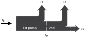
| Couple d'entrée | TE=T1+T2+T3 |
| TE < TE max | |
| Couple en traversée | TD=T2+T3 |
| TD < TD max |
Watch A10VO Series 32 Product Video
Related Selection Resources
Request a A10VO Series 32 Quotation
Tell us your required configuration, quantity and application.
Produits associés
Compare related hydraulic pumps and confirm the complete configuration for your application.


Code de commande
| 01 | 02 | 03 | 04 | 05 | 06 | 07 | 08 | 09 | 10 | 11 | 12 | ||
| A10V | ○ | / | 32 | - | v |
Unité à pistons axiaux
| 01 | Conception à plateau oblique, variable, pression nominale 280 bar, pression maximale 350 bar | A10V |
Mode de fonctionnement
| 02 | Pompe à circuit ouvert | ○ |
Taille (NG)
| 03 | Cylindrée géométrique, voir " Caractéristiques techniques " à la page 7 | 045 | 071 | 100 | 140 | 180 |
Dispositifs de contrôle
| 04 | Régulateur de pression | Hydraulique | ● | ● | ● | ● | ● | Dr | |||
| avec régulateur de débit | Hydraulique | X-T ouvert | ● | ● | ● | ● | ● | DRF | |||
| X-T branché | avec fonction de chasse d'eau | ● | ● | ● | ● | ● | SRD | ||||
| X-T branché | sans fonction de chasse d'eau | ● | ● | ● | ● | ● | DRSC | ||||
| Coupure par pression | Hydraulique | télécommandé | ● | ● | ● | ● | ● | GDR | |||
| électrique | témoin négatif | U=12V | ● | ● | ● | ● | ● | ED71 | |||
| U=24V | ● | ● | ● | ● | ● | ED72 | |||||
| électrique | témoin positif | U=12V | ● | ● | ● | ● | ● | ER711) | |||
| U=24V | ● | ● | ● | ● | ● | ER722) | |||||
| Pression différentielle
contrôle |
électrique | témoin négatif | voir la fiche technique 92709 | ● | ● | ● | ● | ○ | EF. | ||
| Régulateur de puissance avec | |||||||||||
| Coupure par pression | Hydraulique | Début du contrôle | à | 50 bars | ● | ● | ● | ● | ● | LA5D | |
| de | de 51 à 90 bars | ● | ● | ● | ● | ● | LA6D | ||||
| de 91 à 160 bars | ● | ● | ● | ● | ● | LA7D | |||||
| de 161 à 240 bars | ● | ● | ● | ● | ● | LA8D | |||||
| au-dessus | 240 bars | ● | ● | ● | ● | ● | LA9D | ||||
| Coupure de pression et régulation de débit | Hydraulique | Début du contrôle | voir LA.D | ● | ● | ● | ● | ● | LA.DS | ||
| Télécommandé
coupure par pression |
Hydraulique | Début du contrôle | voir LA.D | ● | ● | ● | ● | ● | LA.DG | ||
| Séparation du contrôle de flux | Hydraulique | Début du contrôle | voir LA.D | ● | ● | ● | ● | ● | LA.S | ||
Séries
| 05 | Série 3, indice 2 | 32 |
Sens de rotation
| 06 | Vu sur l'arbre de transmission | dans le sens des aiguilles d'une montre | R |
| dans le sens inverse des aiguilles d'une montre | L |
Phoque
| 07 | FKM (fluoroélastomère) | V |
Arbre de transmission
| 08 | Arbre cannelé
ANSI B92.1a |
arbre standard | ● | ● | ● | ● | ● | S |
| similaire à l'arbre " S ", mais pour un couple d'entrée plus élevé | ● | ● | - | - | - | R | ||
| diamètre réduit, aptitude limitée pour l'entraînement traversant | ● | ● | ● | ● | - | U | ||
| identique à l'arbre " U ", mais pour un couple plus élevé, aptitude limitée pour l'entraînement traversant | - | - | ● | ● | ● | W |
Bride de fixation
| 045 | 071 | 100 | 140 | 180 | 045 | |||
| 09 | ISO 3019-1 (SAE) | SAE C ; 2 trous | ● | ● | ● | ● | - | C |
| SAE C ; 4 trous | ● | ● | ● | ● | ● | D | ||
| SAE D ; 4 trous | - | ● | - | - | - | U |
Port en eau profonde
| 10 | Orifice à bride SAE (Plaques d'orifice et affectation d'entraînement traversant,
voir la position 11) |
filetage de fixation métrique arrière (pas pour entraînement traversant) | ● | ● | ● | ● | ● | 11 |
| en haut, en bas, du côté opposé, filetage de fixation métrique | ● | ● | ● | ● | - | 12 | ||
| en haut, en bas, du côté opposé, filetage de fixation métrique avec entraînement traversant universel U.. ; sans amortissement des pulsations | ○ | ○ | ○ | ○ | ● | 221) | ||
| en haut, en bas, du côté opposé, filetage de fixation métrique avec entraînement traversant universel U.. ; avec amortissement des pulsations | ○ | ○ | ○ | ○ | ● | 321) |
Drive
| 11 | Bride ISO 3019-1
Diamètre |
Attacher
mensonge4) |
Moyeu pour arbre cannelé2)
Diamètre |
|||||||
| 045 | 071 | 100 | 140 | 180 | ||||||
| sans entraînement direct | (Uniquement pour les plaques à orifices 11 et 12) | ● | ● | ● | ● | ● | N00 | |||
| 82-2 (A) |  |
5/8 po | 9T 16/32DP | ● | ● | ● | ● | - | K01 | |
| 3/4 po | 11T 16/32DP | ● | ● | ● | ● | - | K52 | |||
| 101-2 (B) | |
7/8 po | 13T 16/32DP | ● | ● | ● | ● | - | K68 | |
| 1 po | 15T 16/32DP | ● | ● | ● | ● | - | K04 | |||
| 127-2 (C) |  |
1 1/4 po | 14T 12/24DP | - | ● | ● | ● | - | K07 | |
| 1 1/2 po | 17T12/24DP | - | - | ● | ● | - | K24 | |||
| 127-4 (C) |  |
1 1/4 po | 14T 12/24DP | - | ○ | ● | ● | - | K15 | |
| 152-4 (D) | |
1 3/4 po | 13T 8/16DP | - | - | - | ● | - | K17 | |
| sans entraînement direct | (Uniquement possible avec les plaques à orifices 22 et 32)3) | ○ | ○ | ○ | ○ | ● | U00 | |||
| 82-2 (A) | |
5/8 po | 9T 16/32DP | ○ | ○ | ○ | ○ | ● | U01 | |
| 3/4 po | 13T 16/32DP | ○ | ○ | ○ | ○ | ● | U52 | |||
| 101-2(B) | |
7/8 po | 13T 16/32DP | ○ | ○ | ○ | ○ | ● | U68 | |
| 1 po | 15T 16/32DP | ○ | ○ | ○ | ○ | ● | U04 | |||
| 127-2 (C) | |
1 1/4 po | 14T 12/24DP | - | ○ | ○ | ○ | ● | U07 | |
| 1 1/2 po | 17T 12/24DP | - | - | ○ | ○ | ● | U24 | |||
| 127-4 (C) | |
1 sur | 15T 16/32DP | ○ | ○ | ○ | ○ | ○ | UE2 | |
| 1 1/4 po | 14T 12/24DP | - | - | ○ | ○ | ● | U15 | |||
| 152-4 (D) | |
1 3/4 po | 13T 8/16DP | - | - | - | ○ | ● | U17 | |
Connecteurs pour solénoïdes5)
| 12 | Sans connecteur (sans solénoïde, à commande hydraulique uniquement, sans code) | |
| Connecteur moulé DEUTSCH, 2 broches - sans diode de suppression | P |
•=Disponible ○=Sur demande -=Non disponible
Notes
Prenez note des notes de planification du projet à la page 54 !
En plus du code type, veuillez spécifier les données techniques pertinentes lors de votre commande.
1)Uniquement avec bride de fixation (code de commande position 09) D ou U
2)Selon la norme ANSI B92.1a (arbres cannelés selon SAE J744)
3)Avec arbre traversant, sans moyeu, sans bride intermédiaire, fermé de manière fonctionnelle par un couvercle. Pour les kits de montage, voir la fiche technique 95581.
4)Schéma des trous de fixation traversants vu depuis l'entraînement traversant avec la commande en haut.
5)Les connecteurs pour d'autres composants électriques peuvent différer.
Données techniques
| Taille | NG | 045 | 071 | 100 | 140 | 180 | |||
| Cylindrée géométrique par tour | VGiga | cm3 | 45 | 71.1 | 100 | 140 | 180 | ||
| Vitesse de rotation maximale1)2) | at | VGiga | nnom | tours par minute | 3000 | 2550 | 2300 | 2200 | 1800 |
| Flux | at | nnom et VGiga | qv | L/min | 135 | 181 | 230 | 308 | 324 |
| Puissance | at | nnom, VGiga and Δp = 280 bar | P | kW | 63 | 85 | 107 | 144 | 151 |
| Couple | at | VGiga and Δp = 280 bar | T | Rien | 200 | 317 | 446 | 624 | 802 |
| at | VGiga et Δp = 100 bar | T | Rien | 72 | 113 | 159 | 223 | 286 | |
| Rotary stiffness ofdrive shaft | S | c | Nm/rad | 37500 | 71884 | 121142 | 169537 | 171107 | |
| R | c | Nm/rad | 41025 | 76545 | - | - | - | ||
| U | c | Nm/rad | 30077 | 52779 | 91093 | on | - | ||
| request | |||||||||
| W | c | Nm/rad | 34463 | 57460 | 101847 | 165594 | - | ||
| Moment d'inertie pour le groupe rotatif | JTW | Kgm2 | 0.0035 | 0.0087 | 0.0167 | 0.0242 | 0.033 | ||
| Accélération angulaire maximale3) | α | rad/s2 | 4000 | 2900 | 2400 | 2000 | 2000 | ||
| Volume du boîtier | V | L | 1.0 | 1.6 | 2.2 | 3.0 | 2.7 | ||
| Weight (11N00 and 12N00 without through drive) approx. | m | kg | 25.8 | 40.4 | 56.4 | 70.5 | 75.2 | ||
| Weight (12Kxx) approx. | m | kg | 27.4 | 43.3 | 62.6 | 79.5 | - | ||
| Weight (22Uxx/32Uxx)approx. | m | kg | 32.6 | 51.8 | 76 | 90.2 | 89.4 | ||
Définir les caractéristiques de fonctionnement
| Flux | qv=(Vg ∙ n ∙ ηv) / 1000 | L/min |
| Couple | T=(Vg ∙ Δp) / 20 ∙ π ∙ ηhm | Rien |
| Puissance | P=(2π ∙ T ∙ n)/60000=(qv ∙ Δp)/600 ∙ ηt | kW |
Clé
Vg Déplacement par révolution en [cm3]
Δp Pression différentielle [bar]
n Vitesse de rotation [tr/min]
ηv Efficacité volumétrique
ηhm Efficacité hydraulico-mécanique
ηt Efficacité totale (ηt= ηv*ηhm)
Avis
▶Valeurs théoriques, sans efficacité ni tolérances ; valeurs arrondies
▶Operation above the maximum values or below the minimum values may result in a loss of function, a reduced service life or in the destruction of the axial piston unit. Bosch Rexroth recommend testing the load by means of experiment or calculation/simulation and comparison with the permissible values.
1) Les valeurs sont applicables :
- to the optimum viscosity range from Vopt = 36 à 16 mm2/s
- to hydraulic fluid based on mineral oils
2) The values apply at absolute pressure pabdos = 1.0 bar at suction port S.
3)4)The data are valid for values between the minimum required and maximum permissible rotational speed. Valid for external excitation(e.g. diesel engine 2 to 8 times rotary frequency; cardan shaft twice the rotary frequency). The limit value is only valid for a single pump. The load capacity of the connecting parts must be considered.
Forces radiales et axiales admissibles sur l'arbre d'entraînement
| Taille | NG | 45 | 71 | 100 | 140 | 180 | ||
| Force radiale maximale à a/2 | |
Fq max | N | 1500 | 1900 | 2300 | 2800 | 2300 |
| Force axiale maximale | |
±Fax max | N | 1500 | 2400 | 4000 | 4800 | 800 |
Avis
▶For drives with radial loading (pinion, V-belt), please contact us!
cURL Too many subrequests by single Worker invocation. To configure this limit, refer to https://developers.cloudflare.com/workers/wrangler/configuration/#limits
couples d'entrée et de transmission admissibles
| Taille | 45 | 71 | 100 | 140 | 180 | |||
| Couple à VGiga and Δp = 280 bar1) | Tmax | Rien | 200 | 316 | 446 | 624 | 802 | |
| Input torque at drive shaft, maximum2) | ||||||||
| S | TE max | Rien | 319 | 626 | 1104 | 1620 | 1834 | |
| ∅ | in | 1 | 1 1/4 | 1 1/2 | 1 3/4 | 1 3/4 | ||
| R | TE max | Rien | 400 | 644 | - | - | - | |
| ∅ | in | 1 | 1 1/4 | - | - | - | ||
| U | TE max | Rien | 188 | 300 | 595 | on
request |
- | |
| ∅ | in | 7/8 | 1 | 1 1/4 | 1 1/2 | - | ||
| W | TE max | Rien | - | 394 | 636 | 1220 | 1488 | |
| ∅ | in | - | 1 | 1 1/4 | 1 1/2 | 1 1/2 | ||
| Couple maximal en traversée | ||||||||
| S | TD max | Rien | 319 | 492 | 778 | 1266 | 1266 | |
| R | TD max | Rien | 365 | 548 | - | - | - | |
| U | TD max | Rien | 188 | - | 595 | on
request |
- | |
| W | TD max | Rien | - | - | 636 | 1220 | 1266 | |
Répartition des couples
| Couple à la première pompe | T1 |
| Couple à la deuxième pompe | T2 |
| Couple à la troisième pompe | T3 |
| Couple d'entrée | TE=T1+T2+T3 |
| TE < TE max | |
| Couple en traversée | TD=T2+T3 |
| TD < TD max |
1)Efficacité non prise en compte
2) For drive shafts with no radial force
