Wenzhou Prance Hydraulic Equipment Co., Ltd.


A10VO Series 32 Variable Piston Pump
The A10VO Series 32 variable pump is offered with ISO mounting, SAE metric flange connections and two case-drain ports. Its model series and control suffix must be preserved when checking a replacement against another A10VO generation.
- Series 32 pump identification
- ISO mounting reference
- SAE metric flange connections
- Two case-drain ports
PRANCE HYDRAULIC · PRODUCT SERIES
A10VO Series 32 Variable Piston Pump
Axial piston; variable swashplate · Open circuit
The A10VO Series 32 variable pump is offered with ISO mounting, SAE metric flange connections and two case-drain ports. Its model series and control suffix must be preserved when checking a replacement against another A10VO generation.
Model
✓
Request a QuotationTechnische Daten & Datenblatt anzeigenA10VO Series 32Axial piston; variable swashplate
Confirm the complete model and approved specification with Prance Hydraulic. Product-series references alone do not establish interchangeability.
Configuration review · Technical documentation · Product selection
Produktdetails
- Series 32 pump identification
- ISO mounting reference
- SAE metric flange connections
- Two case-drain ports
CATEGORIES: Kolbenpumpe, Verstellpumpe
A10VO Series 32 Features & Application
Series 32 pump identification
Include the series and all order-code suffixes in the enquiry. A common nominal size does not establish compatibility.
ISO mounting reference
Check pilot diameter, bolt pattern, shaft engagement or port pattern against the approved installation drawing.
SAE metric flange connections
Check pilot diameter, bolt pattern, shaft engagement or port pattern against the approved installation drawing.
Two case-drain ports
Specify the full A17FO Series 10 order code, installation drawing and operating duty so the quotation can identify the proposed configuration.
A10VO Series 32 Specifications
| Series / model | A10VO Series 32 |
|---|---|
| Product type | A10VO Series 32 Variable Piston Pump |
| Design | Axial piston; variable swashplate |
| Circuit / selection | Open circuit |
| Published nominal sizes | 45, 71, 100, 140 and 180 |
| Listed maximum geometric displacement | 45, 71.1, 100, 140 and 180 cm³/rev |
A10VO Series 32 Selection & Configuration
The A10VO Series 32 variable pump is offered with ISO mounting, SAE metric flange connections and two case-drain ports. Its model series and control suffix must be preserved when checking a replacement against another A10VO generation.
Identify the required mounting, shaft and port orientation using the drawing, then choose the drain port appropriate to the installation. Match the control function and operating point to the Series 32 data rather than reusing Series 31 settings without review.

cURL Too many subrequests by single Worker invocation. To configure this limit, refer to https://developers.cloudflare.com/workers/wrangler/configuration/#limits.
cURL Too many subrequests by single Worker invocation. To configure this limit, refer to https://developers.cloudflare.com/workers/wrangler/configuration/#limits.
Hydraulic pumps · Hydraulic motors · Hydraulic valves
Send the A17FO Series 10 nameplate, operating requirements and installation drawing for a configuration review before quoting.
- Model review — send the full model code or an existing nameplate photograph.
- Interface matching — confirm shaft, mounting flange, rotation and ports.
- Operating conditions — provide flow, pressure, speed, fluid and duty cycle.
- Documentation — request the relevant product data and drawings for your review.

A10VO Series 32 Buying Guide
Use this sequence to prepare the A10VO Series 53 configuration for review and quotation.
- Define required flow at the actual drive speed and continuous pressure.
- Identify peak pressure, duration and the work cycle.
- Confirm the selected displacement control and any auxiliary-drive requirement.
- Match rotation viewed from the shaft end, shaft, flange and ports.
- Review inlet conditions, drain routing and the installation envelope.
- Confirm fluid, viscosity, temperature, filtration and seals.
- Approve the complete model, control, drawing, quantity and delivery terms.

Selection, Documentation & Project Support

Selection Support
Learn more →Share your hydraulic circuit, operating point and installation requirements for a configuration discussion.
Flow · Pressure · Speed · Interfaces

Technical Resources
Learn more →Review product documentation, model codes and technical data before finalizing the specification.
Datasheets · Model codes · Drawings

Project Inquiries
Learn more →Send your required model, quantity, application and project requirements to discuss your inquiry.
Product inquiries · Configuration review
Configuration, Quantity & Delivery
Confirm the complete A17FO Series 10 code, approved drawing and operating limits. Availability, quantity, documentation and delivery date are confirmed in the quotation.
Discuss Your A10VO Series 32 Application
Send the full model code, operating duty, installation details and quantity.
Request a A10VO Series 32 QuotationA10VO Series 32 Questions Before Ordering
What type of product is the A10VO Series 32?
A10VO Series 32 Variable Piston Pump. Design: Axial piston; variable swashplate. Open circuit. Confirm the complete order code for the offered version.
Can a similar pump replace the A10VO Series 32?
cURL Too many subrequests by single Worker invocation. To configure this limit, refer to https://developers.cloudflare.com/workers/wrangler/configuration/#limits.
cURL Too many subrequests by single Worker invocation. To configure this limit, refer to https://developers.cloudflare.com/workers/wrangler/configuration/#limits
Define required flow at the actual drive speed and continuous pressure. Identify peak pressure, duration and the work cycle. Attach the nameplate, complete order code, installation drawing and required quantity.
A10VO Series 32 Technical Data & Documents
View A10VO Series 32 catalog data and operating conditions
cURL Too many subrequests by single Worker invocation. To configure this limit, refer to https://developers.cloudflare.com/workers/wrangler/configuration/#limits.
Technische Daten
| Größe | NG | 045 | 071 | 100 | 140 | 180 | |||
| Geometrisches Fördervolumen pro Umdrehung | VG-Max | cm3 | 45 | 71.1 | 100 | 140 | 180 | ||
| Maximale Drehzahl1)2) | bei | VG-Max | nnom | U/min | 3000 | 2550 | 2300 | 2200 | 1800 |
| Drehmoment | bei | VG-Max und Δp = 280 bar | T | Machs gut | 200 | 317 | 446 | 624 | 802 |
| bei | VG-Max und Δp = 100 bar | T | Machs gut | 72 | 113 | 159 | 223 | 286 | |
| Verdrehsteifigkeit der Gelenkwelle | S | c | Nm/rad | 37500 | 71884 | 121142 | 169537 | 171107 | |
| R | c | Nm/rad | 41025 | 76545 | – | – | – | ||
| U | c | Nm/rad | 30077 | 52779 | 91093 | an | – | ||
| Anfrage | |||||||||
| W | c | Nm/rad | 34463 | 57460 | 101847 | 165594 | – | ||
| Trägheitsmoment der Drehgruppe | JTW | Kgm2 | 0.0035 | 0.0087 | 0.0167 | 0.0242 | 0.033 | ||
| Maximale Winkelbeschleunigung3) | α | rad/s2 | 4000 | 2900 | 2400 | 2000 | 2000 | ||
| Fallzahl | V | L | 1.0 | 1.6 | 2.2 | 3.0 | 2.7 | ||
| Gewicht (11N00 und 12N00 ohne Durchtrieb) ca. | m | kg | 25.8 | 40.4 | 56.4 | 70.5 | 75.2 | ||
| Gewicht (12Kxx) ca. | m | kg | 27.4 | 43.3 | 62.6 | 79.5 | – | ||
| Gewicht (22Uxx/32Uxx) ca. | m | kg | 32.6 | 51.8 | 76 | 90.2 | 89.4 | ||
Bestimmung der Betriebskennlinien
Schlüssel
Vg Fördervolumen pro Umdrehung in [cm3] Δp Differential pressure [bar] n Rotational speed [rpm] ηv Volumetric efficiency ηmh Hydraulic-mechanical efficiency ηt Gesamtwirkungsgrad (ηt= ηv*ηhm)Hinweis
▶Theoretical values, without efficiency and tolerances;values rounded ▶Operation above the maximum values or below the minimum values may result in a loss of function,a reduced service life or in the destruction of the axial piston unit. Prance recommends testing the loads by means of experiment or calculation /simulation and comparison with the permissible values. 1) The values are applicable: – to the optimum viscosity range from Ventscheiden = 36 bis 16 mm2/s – to hydraulic fluid based on mineral oils 2) Die Werte gelten beim absoluten Druck pABS = 1,0 bar am Saugstutzen S. 3)Die Daten gelten für Werte zwischen der minimal erforderlichen und der maximal zulässigen Drehzahl. Gültig für äußere Erregung (z. B. Dieselmotor das 2- bis 8-fache der Drehfrequenz, Kardanwelle das doppelte der Drehfrequenz). Der Grenzwert gilt nur für eine einzelne Pumpe. Die Belastbarkeit der Verbindungsteile muss berücksichtigt werden.Zulässige Radial- und Axialkräfte auf die Antriebswelle
| Größe | NG | 45 | 71 | 100 | 140 | 180 | ||
| Maximale Radialkraft bei a/2 |  |
FQ-max | N | 1500 | 1900 | 2300 | 2800 | 2300 |
| Maximale Axialkraft |  |
±FAch, Max | N | 1500 | 2400 | 4000 | 4800 | 800 |
Hinweis
▶For drives with radial loading (pinion, V-belt), please contact us! ▶The values given are maximum values and do not apply to continuous operation.Zulässige Eingangs- und Durchtriebsdrehmomente
| Größe | 45 | 71 | 100 | 140 | 180 | |||
| Eingangsdrehmoment an Antriebswelle, maximal2) | ||||||||
| S | TE max | Machs gut | 319 | 626 | 1104 | 1620 | 1834 | |
| ∅ | in | 1 | 1 1/4 | 1 1/2 | 1 3/4 | 1 3/4 | ||
| R | TE max | Machs gut | 400 | 644 | – | – | – | |
| ∅ | in | 1 | 1 1/4 | – | – | – | ||
| U | TE max | Machs gut | 188 | 300 | 595 | on request | – | |
| ∅ | in | 7/8 | 1 | 1 1/4 | 1 1/2 | – | ||
| W | TE max | Machs gut | – | 394 | 636 | 1220 | 1488 | |
| ∅ | in | – | 1 | 1 1/4 | 1 1/2 | 1 1/2 | ||
| Maximales Durchtriebsdrehmoment | ||||||||
| S | TD max | Machs gut | 319 | 492 | 778 | 1266 | 1266 | |
| R | TD max | Machs gut | 365 | 548 | – | – | – | |
| U | TD max | Machs gut | 188 | – | 595 | on request | – | |
| W | TD max | Machs gut | – | – | 636 | 1220 | 1266 | |
Drehmomentverteilung
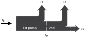
| Eingangsdrehmoment | TE=T1+T2+T3 |
| TE < TE max | |
| Durchtriebsdrehmoment | TD=T2+T3 |
| TD < TD max |
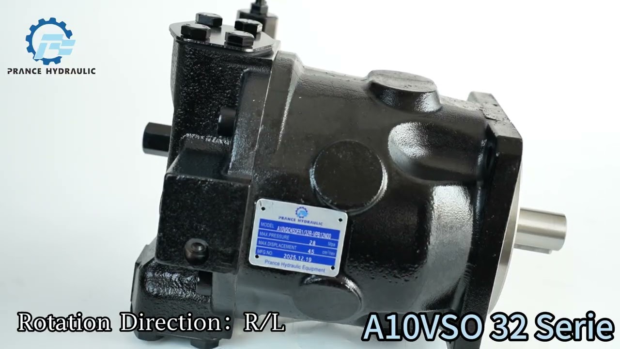
Watch A10VO Series 32 Product Video
Related Selection Resources
Request a A10VO Series 32 Quotation
Tell us your required configuration, quantity and application.
Ähnliche Produkte
Compare related hydraulic pumps and confirm the complete configuration for your application.


Bestellcode
| 01 | 02 | 03 | 04 | 05 | 06 | 07 | 08 | 09 | 10 | 11 | 12 | ||
| A10V | ○ | / | 32 | - | v |
Axialkolbeneinheit
| 01 | Schrägtscheibenbauweise, verstellbar, Nenndruck 280 bar, Maximaldruck 350 bar | A10V |
Betriebsart
| 02 | Pumpe, offener Kreisklauf | ○ |
Größe (NG)
| 03 | Geometrisches Verdrängungsvolumen, siehe "Technische Daten" auf Seite 7 | 045 | 071 | 100 | 140 | 180 |
Steuergeräte
| 04 | Druckregler | Hydraulisch | ● | ● | ● | ● | ● | DR | |||
| mit Durchflussregler | Hydraulisch | X-T öffnen | ● | ● | ● | ● | ● | DRF | |||
| X-T eingesteckt | mit Spülfunktion | ● | ● | ● | ● | ● | DRS | ||||
| X-T eingesteckt | ohne Spülfunktion | ● | ● | ● | ● | ● | DRSC | ||||
| Druckabschaltung | Hydraulisch | fernbedient | ● | ● | ● | ● | ● | DRG | |||
| elektrisch | Negativkontrolle | U=12V | ● | ● | ● | ● | ● | ED71 | |||
| U=24V | ● | ● | ● | ● | ● | ED72 | |||||
| elektrisch | Positivkontrolle | U=12V | ● | ● | ● | ● | ● | ER711) | |||
| U=24V | ● | ● | ● | ● | ● | ER722) | |||||
| Differenzdruck
Steuerung |
elektrisch | Negativkontrolle | siehe Datenblatt 92709 | ● | ● | ● | ● | ○ | EF. | ||
| Leistungsregler mit | |||||||||||
| Druckabschaltung | Hydraulisch | Beginn der Steuerung | zu | 50 bar | ● | ● | ● | ● | ● | LA5D | |
| von | 51 bis 90 bar | ● | ● | ● | ● | ● | LA6D | ||||
| 91 bis 160 bar | ● | ● | ● | ● | ● | LA7D | |||||
| 161 bis 240 bar | ● | ● | ● | ● | ● | LA8D | |||||
| oben | 240 bar | ● | ● | ● | ● | ● | LA9D | ||||
| Druckabschaltung und Volumenstromregelung | Hydraulisch | Beginn der Steuerung | siehe LA.D | ● | ● | ● | ● | ● | LA.DS | ||
| Ferngesteuert
Druckabschaltung |
Hydraulisch | Beginn der Steuerung | siehe LA.D | ● | ● | ● | ● | ● | LA.DG | ||
| Separate flow control | Hydraulisch | Beginn der Steuerung | siehe LA.D | ● | ● | ● | ● | ● | LA.S | ||
Serie
| 05 | Reihe 3, Index 2 | 32 |
Drehrichtung
| 06 | Auf Antriebswelle betrachtet | im Uhrzeigersinn | R |
| gegen den Uhrzeigersinn | L |
Robbe
| 07 | FKM (Fluorelastomer) | V |
Antriebswelle
| 08 | Kerbwelle
ANSI B92.1a |
Standardwelle | ● | ● | ● | ● | ● | S |
| ähnlich wie Welle "S", jedoch für höheres Eingangsdrehmoment | ● | ● | - | - | - | R | ||
| reduzierter Durchmesser, eingeschränkte Eignung für den Durchtrieb | ● | ● | ● | ● | - | U | ||
| wie Welle "U", jedoch für höheres Drehmoment, bedingt geeignet für Durchtrieb | - | - | ● | ● | ● | W |
Montageflansch
| 045 | 071 | 100 | 140 | 180 | 045 | |||
| 09 | ISO 3019-1 (SAE) | SAE C; 2-Loch | ● | ● | ● | ● | - | C |
| SAE C; 4-Loch | ● | ● | ● | ● | ● | D | ||
| SAE D; 4-Loch | - | ● | - | - | - | U |
Funktionierender Port
| 10 | SAE-Flanschanschluss (Anschlussplatten- und Durchtriebszuordnung),
siehe Position 11) |
Rückseitiges metrisches Befestigungsgewinde (nicht für Durchsteckmontage) | ● | ● | ● | ● | ● | 11 |
| oben, unten, auf der gegenüberliegenden Seite, metrisches Befestigungsgewinde | ● | ● | ● | ● | - | 12 | ||
| oben, unten, auf der gegenüberliegenden Seite, metrisches Befestigungsgewinde mit universellem Durchtrieb U..; ohne Pulsationsdämpfung | ○ | ○ | ○ | ○ | ● | 221) | ||
| oben, unten, auf der gegenüberliegenden Seite, metrisches Befestigungsgewinde mit universellem Durchtrieb U..; mit Pulsationsdämpfung | ○ | ○ | ○ | ○ | ● | 321) |
Durchfahrt
| 11 | Flansch ISO 3019-1
Durchmesser |
Anhängen
ment4) |
Nabe für Keilwelle2)
Durchmesser |
|||||||
| 045 | 071 | 100 | 140 | 180 | ||||||
| ohne Durchgangsantrieb | (Nur für Anschlussplatten 11 und 12) | ● | ● | ● | ● | ● | N00 | |||
| 82-2 (A) |  |
5/8 Zoll | 9T 16/32DP | ● | ● | ● | ● | - | K01 | |
| 3/4 Zoll | 11Z 16/32DP | ● | ● | ● | ● | - | K52 | |||
| 101-2 (B) | |
7/8 Zoll | 13Z 16/32DP | ● | ● | ● | ● | - | K68 | |
| 1 in | 15Z 16/32DP | ● | ● | ● | ● | - | K04 | |||
| 127-2 (C) |  |
1 1/4 Zoll | 14Z 12/24DP | - | ● | ● | ● | - | K07 | |
| 1 1/2 Zoll | 17T12/24DP | - | - | ● | ● | - | K24 | |||
| 127-4 (C) |  |
1 1/4 Zoll | 14Z 12/24DP | - | ○ | ● | ● | - | K15 | |
| 152-4 (D) | |
1 3/4 Zoll | 13T 8/16DP | - | - | - | ● | - | K17 | |
| ohne Durchgangsantrieb | (Nur mit Anschlussplatten 22 und 32 möglich)3) | ○ | ○ | ○ | ○ | ● | U00 | |||
| 82-2 (A) | |
5/8 Zoll | 9T 16/32DP | ○ | ○ | ○ | ○ | ● | U01 | |
| 3/4 Zoll | 13Z 16/32DP | ○ | ○ | ○ | ○ | ● | U52 | |||
| 101-2(B) | |
7/8 Zoll | 13Z 16/32DP | ○ | ○ | ○ | ○ | ● | U68 | |
| 1 in | 15Z 16/32DP | ○ | ○ | ○ | ○ | ● | U04 | |||
| 127-2 (C) | |
1 1/4 Zoll | 14Z 12/24DP | - | ○ | ○ | ○ | ● | U07 | |
| 1 1/2 Zoll | 17T 12/24DP | - | - | ○ | ○ | ● | U24 | |||
| 127-4 (C) | |
1 in | 15Z 16/32DP | ○ | ○ | ○ | ○ | ○ | UE2 | |
| 1 1/4 Zoll | 14Z 12/24DP | - | - | ○ | ○ | ● | U15 | |||
| 152-4 (D) | |
1 3/4 Zoll | 13T 8/16DP | - | - | - | ○ | ● | U17 | |
Steckverbinder für Magnetventile5)
| 12 | Ohne Stecker (ohne Magnetventil, nur mit hydraulischer Steuerung, ohne Code) | |
| DEUTSCH Flachsteckergehäuse, 2-polig – ohne Löschdiode | P |
•=Verfügbar ○=Auf Anfrage -=Nicht verfügbar
Notizen
Beachten Sie die Projektplanungsnotizen auf Seite 54!
Bitte geben Sie bei Ihrer Bestellung zusätzlich zum Typencode die relevanten technischen Daten an.
1)Nur mit Befestigungsflansch (Bestellcode Position 09) D oder U
2)Nach ANSI B92.1a (Keilwellen nach SAE J744)
3)Mit Durchtriebswelle, ohne Nabe, ohne Zwischenflansch, funktionssicher mit Deckel verschlossen. Für Anbausätze siehe Datenblatt 95581.
4)Anordnung der Befestigungsdurchgangslöcher, gesehen vom Durchtrieb aus mit der Steuerung oben.
5)Anschlüsse für andere elektrische Komponenten können abweichen.
Technische Daten
| Größe | NG | 045 | 071 | 100 | 140 | 180 | |||
| Geometrisches Fördervolumen pro Umdrehung | VG-Max | cm3 | 45 | 71.1 | 100 | 140 | 180 | ||
| Maximale Drehzahl1)2) | bei | VG-Max | nnom | U/min | 3000 | 2550 | 2300 | 2200 | 1800 |
| Fluss | bei | nnom und VG-Max | qv | l/min | 135 | 181 | 230 | 308 | 324 |
| Macht | bei | nnom, VG-Max und Δp = 280 bar | P | kW | 63 | 85 | 107 | 144 | 151 |
| Drehmoment | bei | VG-Max und Δp = 280 bar | T | Machs gut | 200 | 317 | 446 | 624 | 802 |
| bei | VG-Max und Δp = 100 bar | T | Machs gut | 72 | 113 | 159 | 223 | 286 | |
| Verdrehsteifigkeit der Gelenkwelle | S | c | Nm/rad | 37500 | 71884 | 121142 | 169537 | 171107 | |
| R | c | Nm/rad | 41025 | 76545 | - | - | - | ||
| U | c | Nm/rad | 30077 | 52779 | 91093 | an | - | ||
| Anfrage | |||||||||
| W | c | Nm/rad | 34463 | 57460 | 101847 | 165594 | - | ||
| Trägheitsmoment der Drehgruppe | JTW | Kgm2 | 0.0035 | 0.0087 | 0.0167 | 0.0242 | 0.033 | ||
| Maximale Winkelbeschleunigung3) | α | rad/s2 | 4000 | 2900 | 2400 | 2000 | 2000 | ||
| Fallzahl | V | L | 1.0 | 1.6 | 2.2 | 3.0 | 2.7 | ||
| Gewicht (11N00 und 12N00 ohne Durchtrieb) ca. | m | kg | 25.8 | 40.4 | 56.4 | 70.5 | 75.2 | ||
| Gewicht (12Kxx) ca. | m | kg | 27.4 | 43.3 | 62.6 | 79.5 | - | ||
| Gewicht (22Uxx/32Uxx) ca. | m | kg | 32.6 | 51.8 | 76 | 90.2 | 89.4 | ||
Bestimmung der Betriebskennlinien
| Fluss | qv=(Vg ∙ n ∙ ηv) / 1000 | l/min |
| Drehmoment | T=(Vg ∙ Δp) / 20 ∙ π ∙ ηmh | Machs gut |
| Macht | P=(2π ∙ T ∙ n)/60000=(qv ∙ Δp)/600 ∙ ηt | kW |
Schlüssel
Vg Fördervolumen pro Umdrehung in [cm3]
Δp Differenzdruck [bar]
n Drehzahl [U/min]
ηv Volumetrischer Wirkungsgrad
ηmh Hydraulisch-mechanischer Wirkungsgrad
ηt Gesamtwirkungsgrad (ηt= ηv*ηhm)
Hinweis
▶ Theoretische Werte, ohne Wirkungsgrad und Toleranzen; Werte gerundet
▶Der Betrieb oberhalb der Maximalwerte oder unterhalb der Minimalwerte kann zum Funktionsverlust, zu einer verkürzten Lebensdauer oder zur Zerstörung der Axialkolbeneinheit führen. Bosch Rexroth empfiehlt, die Belastung durch Experimente oder Berechnung/Simulation zu überprüfen und mit den zulässigen Werten zu vergleichen.
1) Die Werte gelten:
- auf den optimalen Viskositätsbereich von Ventscheiden = 36 bis 16 mm2/s
- auf Basis von Mineralölen als Hydraulikflüssigkeit
2) Die Werte gelten beim absoluten Druck pABS = 1,0 bar am Saugstutzen S.
3)Die Daten gelten für Werte zwischen der minimal erforderlichen und der maximal zulässigen Drehzahl. Gültig für äußere Erregung (z. B. Dieselmotor das 2- bis 8-fache der Drehfrequenz, Kardanwelle das doppelte der Drehfrequenz). Der Grenzwert gilt nur für eine einzelne Pumpe. Die Belastbarkeit der Verbindungsteile muss berücksichtigt werden.
Zulässige Radial- und Axialkräfte auf die Antriebswelle
| Größe | NG | 45 | 71 | 100 | 140 | 180 | ||
| Maximale Radialkraft bei a/2 | |
FQ-max | N | 1500 | 1900 | 2300 | 2800 | 2300 |
| Maximale Axialkraft | |
±FAch, Max | N | 1500 | 2400 | 4000 | 4800 | 800 |
Hinweis
▶Bei Antrieben mit Radialbelastung (Ritzel, Keilriemen) sprechen Sie uns bitte an!
▶Die angegebenen Werte sind Höchstwerte und gelten nicht für den Dauerbetrieb.
Zulässige Eingangs- und Durchtriebsdrehmomente
| Größe | 45 | 71 | 100 | 140 | 180 | |||
| Drehmoment bei VG-Max und Δp = 280 bar1) | TMax | Machs gut | 200 | 316 | 446 | 624 | 802 | |
| Eingangsdrehmoment an Antriebswelle, maximal2) | ||||||||
| S | TE max | Machs gut | 319 | 626 | 1104 | 1620 | 1834 | |
| ∅ | in | 1 | 1 1/4 | 1 1/2 | 1 3/4 | 1 3/4 | ||
| R | TE max | Machs gut | 400 | 644 | - | - | - | |
| ∅ | in | 1 | 1 1/4 | - | - | - | ||
| U | TE max | Machs gut | 188 | 300 | 595 | an
Anfrage |
- | |
| ∅ | in | 7/8 | 1 | 1 1/4 | 1 1/2 | - | ||
| W | TE max | Machs gut | - | 394 | 636 | 1220 | 1488 | |
| ∅ | in | - | 1 | 1 1/4 | 1 1/2 | 1 1/2 | ||
| Maximales Durchtriebsdrehmoment | ||||||||
| S | TD max | Machs gut | 319 | 492 | 778 | 1266 | 1266 | |
| R | TD max | Machs gut | 365 | 548 | - | - | - | |
| U | TD max | Machs gut | 188 | - | 595 | an
Anfrage |
- | |
| W | TD max | Machs gut | - | - | 636 | 1220 | 1266 | |
Drehmomentverteilung
| Drehmoment an der 1. Pumpe | T1 |
| Drehmoment an der 2. Pumpe | T2 |
| Drehmoment an der 3. Pumpe | T3 |
| Eingangsdrehmoment | TE=T1+T2+T3 |
| TE < TE max | |
| Durchtriebsdrehmoment | TD=T2+T3 |
| TD < TD max |
1)Effizienz nicht berücksichtigt
2) Für Gelenkwellen ohne Radialkraft
