Wenzhou Prance Hydraulic Equipment Co., Ltd.

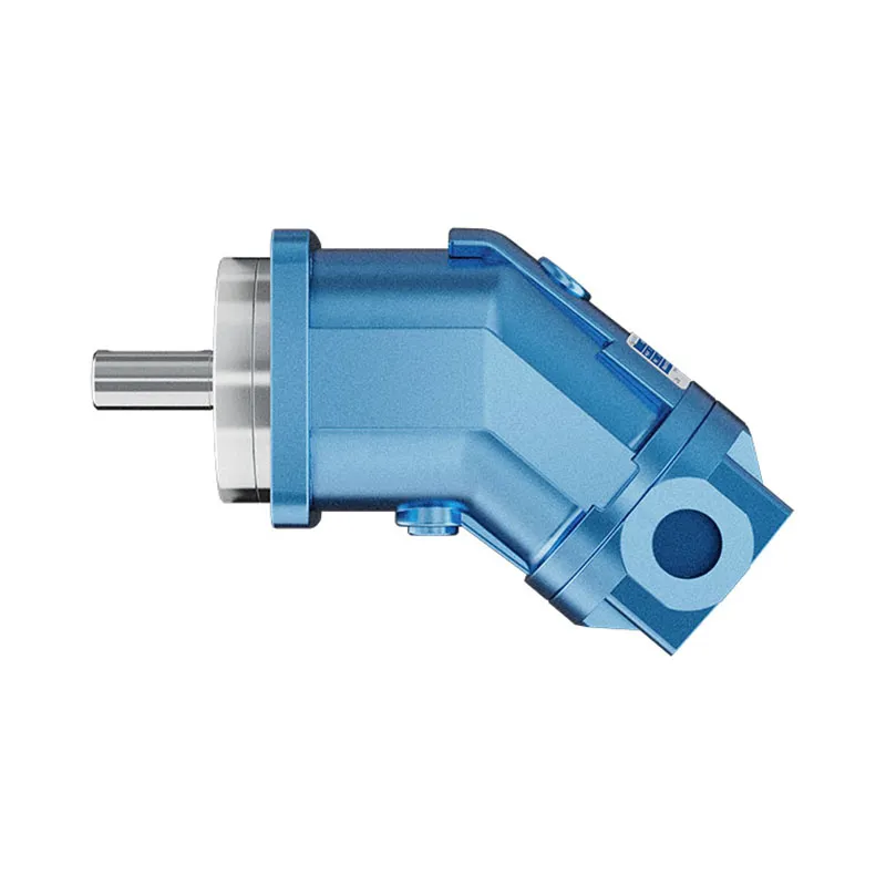
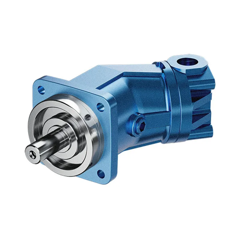
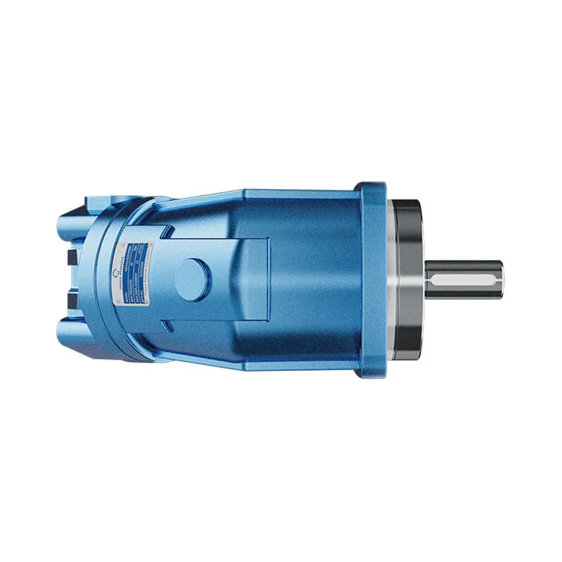
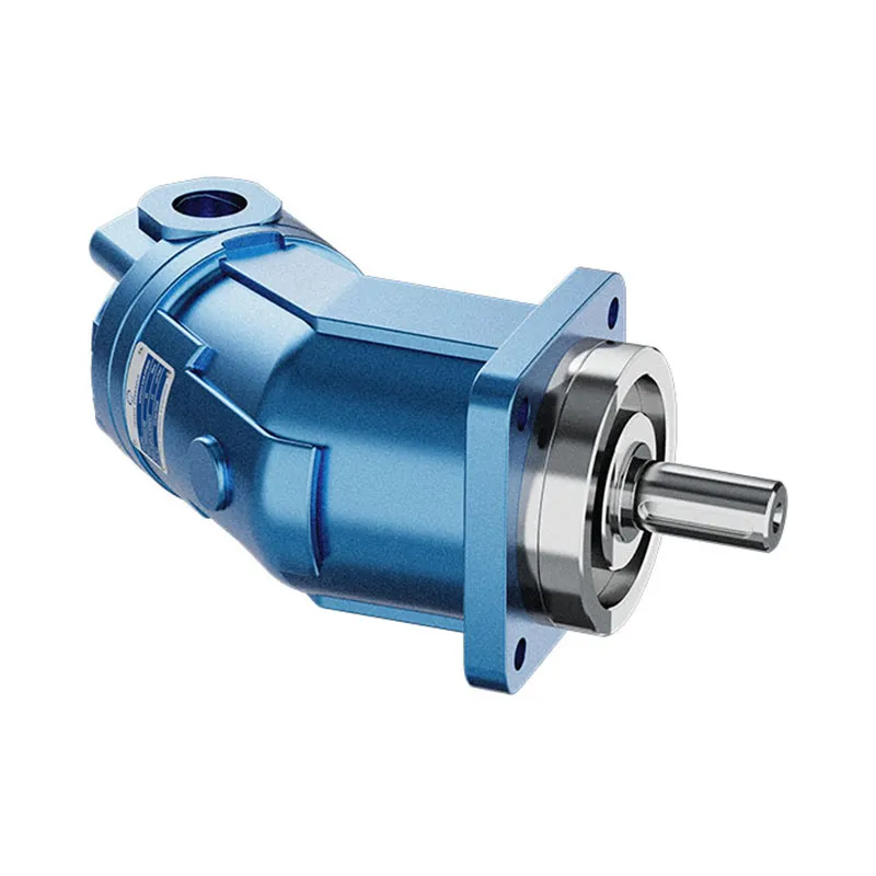
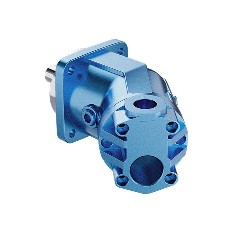
Axialkolben-Konstantpumpe der Serie A2FO
1. Axialkolben-Konstantpumpe A2FO in Schrägachsenbauweise, geeignet für hydrostatische Antriebe in offenen Kreisläufen.
2. Einsatz in mobilen und industriellen Anwendungen
Der Ausgangsfluss ist proportional zu Antriebsdrehzahl und Verdrängung.
Die Antriebswellenlager sind so ausgelegt, dass sie die in diesen Einsatzbereichen erwartete Lebensdauer erbringen.
5. Hohe Leistungsdichte
Axialkolben-Konstantpumpe der Serie A2FO
Fixed displacement, bent-axis pump for open-circuit hydrostatic drives
The A2FO series combines an axial piston, bent-axis design with fixed displacement for mobile and industrial hydraulic applications. Output flow is proportional to drive speed and displacement, with the final configuration selected to match your hydraulic system.
Model
✓
Request a QuotationA2FO Series Axial Piston PumpFixed displacement · Bent-axis design · Open circuit
Configuration review · Technical documentation · Product selection
◉Fixed Displacement
⟲Offener Stromkreis
▦Mobile & Industrial
Produktdetails
- Fixed displacement axial piston pump with bent-axis design
- Suitable for hydrostatic drives in open circuits
- Use in mobile and industrial applications
- Output flow proportional to drive speed and displacement
- Drive shaft bearings designed for these areas of operation
- Compact construction with high power density
CATEGORIES: Kolbenpumpe, Konstantpumpe
Beschreibung
Key Features & Typical Use
Open-circuit operation
A fixed displacement pump for hydrostatic drives in open circuits. Match the inlet conditions and circuit arrangement to the approved technical data.
Bent-axis construction
The axial piston, bent-axis design offers a compact pump layout with high power density for mobile and industrial hydraulic installations.
Speed-dependent flow
For a fixed displacement, output flow varies with drive speed and volumetric efficiency. Confirm your required flow at the intended operating speed.
Configuration matching
Choose the shaft, mounting flange, rotation, seals and service-line ports for the installation. Nominal size alone does not establish compatibility.
Specifications
| Serie | A2FO |
|---|---|
| Product Type | Axial piston fixed displacement pump |
| Design | Bent axis |
| Schaltkreis | Open circuit |
| Anwendungen | Mobile and industrial hydraulic drives |
| Nominal Sizes Listed | 10, 12, 16, 23, 28, 32, 45, 56, 63, 80, 90, 107, 125, 160, 180 |
| Listed Displacement Range | 10.3–180 mL/rev |
| Drehung | Clockwise or counterclockwise; confirm selected model code |
| Robben | NBR or FKM options listed; confirm configuration and fluid compatibility |
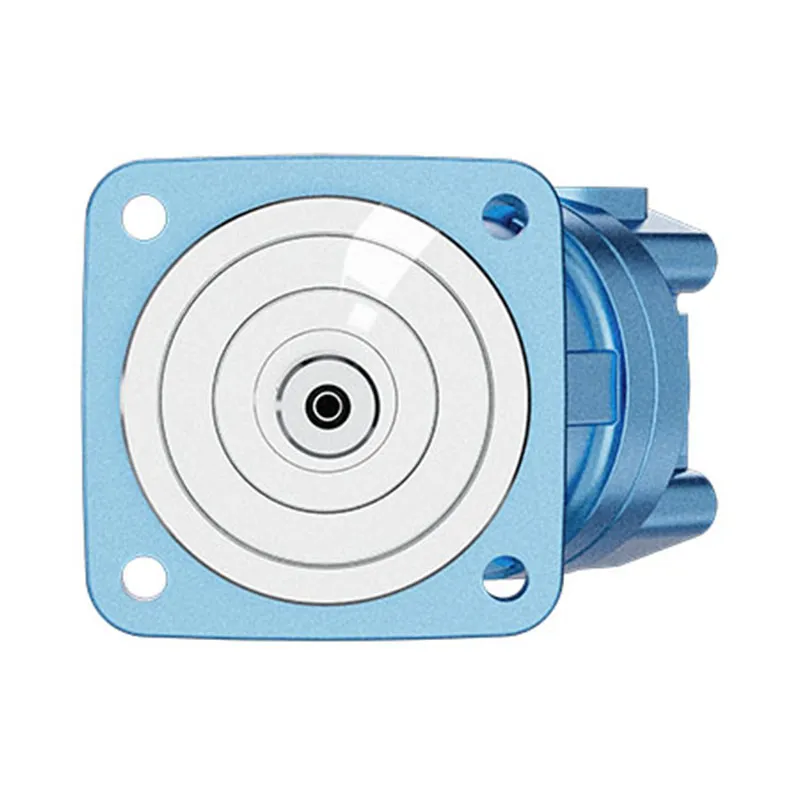
| Mounting, Shaft & Ports | Confirm availability for the selected nominal size in the datasheet |
| Technical Documentation | A2FO Series Datasheet — Download PDF ↗ |
A2FO Series — Fixed Displacement Power for Open-Circuit Systems
The A2FO is a fixed displacement pump with an axial piston, bent-axis design. It is intended for hydrostatic drives in open circuits and is used in mobile machinery and industrial hydraulic installations.
Flow depends on displacement, drive speed and volumetric efficiency. Select the pump around your required operating point, then check the shaft, flange, rotation and connections against the installation.
The product’s compact design and drive shaft bearings support its intended mobile and industrial use. Final operating limits must be confirmed for the selected configuration.
Hydraulic Product & Configuration Support
Your Application.
The Right Configuration.
Hydraulic pumps · Hydraulic motors · Hydraulic valves
Prance provides hydraulic products and application support. For the A2FO series, begin with the hydraulic circuit and installation requirements so the proposed configuration can be reviewed before ordering.
- Model review — send the full model code or an existing nameplate photograph.
- Interface matching — confirm shaft, mounting flange, rotation and ports.
- Operating conditions — provide flow, pressure, speed, fluid and duty cycle.
- Documentation — request the relevant product data and drawings for your review.

Buying Guide
Before ordering an A2FO pump, confirm the operating point and mechanical interface. For a replacement, a full model code and clear photographs help establish the starting configuration.
- Confirm the required displacement or flow at operating speed.
- Specify continuous and peak system pressure and duty cycle.
- Review the open-circuit layout and inlet conditions.
- Confirm direction of rotation viewed from the shaft end.
- Match the shaft, mounting flange and service-line ports.
- Specify the fluid, seals, filtration and temperature requirements.
- Review the proposed model, documentation and quantity before ordering.
How We Support Your Business

Selection Support
Learn more →Share your hydraulic circuit, operating point and installation requirements for a configuration discussion.
Flow · Pressure · Speed · Interfaces

Technical Resources
Learn more →Review product documentation, model codes and technical data before finalizing the specification.
Datasheets · Model codes · Drawings

Project Inquiries
Learn more →Send your required model, quantity, application and project requirements to discuss your inquiry.
Product inquiries · Configuration review
Looking for the Right A2FO Pump for Your Application?
Send your model code, required flow and pressure, installation details and quantity.
Start a product discussion with the Prance team.
Häufig gestellte Fragen
Is the A2FO a fixed displacement pump?
Yes. The A2FO is a fixed displacement axial piston pump with a bent-axis design. Its displacement is not adjusted by a variable displacement control.
Which hydraulic circuit is it intended for?
The current Prance product page specifies open-circuit hydrostatic drives in mobile and industrial applications. Confirm inlet conditions, duty cycle and operating limits before selection.
How do I select the correct A2FO size?
Start with required flow, operating speed, continuous and peak pressure. Then confirm rotation, shaft, mounting flange, ports, fluid and seals against the approved datasheet.
What should I send for a replacement pump inquiry?
Send a clear photograph of the existing nameplate, the full model code if available, mounting dimensions, shaft and port details, operating conditions and required quantity.
Where can I find technical data and the model code?
The original A2FO PDF is linked below. Use it to review the model code and technical data, and confirm the final configuration with Prance before ordering.
A2FO Technical Data
View the listed size, displacement, speed and flow table
| Nennmaß | Verschiebung mL/rev | Listed speed¹ U/min | Theoretical flow L/min at listed speed |
|---|---|---|---|
| A2FO 10 | 10.3 | 3,150 | 32.4 |
| A2FO 12 | 12 | 3,150 | 37.8 |
| A2FO 16 | 16 | 3,150 | 50 |
| A2FO 23 | 22.9 | 2,500 | 57 |
| A2FO 28 | 28.1 | 2,500 | 70 |
| A2FO 32 | 32 | 2,500 | 80 |
| A2FO 45 | 45.6 | 2,240 | 102 |
| A2FO 56 | 56.1 | 2,000 | 112 |
| A2FO 63 | 63 | 2,000 | 126 |
| A2FO 80 | 80.4 | 1,800 | 144 |
| A2FO 90 | 90 | 1,800 | 162 |
| A2FO 107 | 106.7 | 1,600 | 170 |
| A2FO 125 | 125 | 1,600 | 200 |
| A2FO 160 | 160.4 | 1,450 | 232 |
| A2FO 180 | 180 | 1,450 | 261 |
Reference values from the original Prance A2FO page. Speed values apply at 0.1 MPa absolute inlet pressure with mineral oil of density 0.88 kg/L. Flow values are theoretical and rounded. Confirm all limits and conditions against the approved datasheet.
Watch A2FO Product Video
Ähnliche Produkte
Explore more hydraulic pumps from Prance.


Modellcode
| A2F | ○ | 80 | /6 | 1 | R | -P | A | B | 0.5 |
| Axialkolbeneinheit | Betriebsart | Größe (ml/r) | Serie | Index | Drehrichtung | Robben | Wellenende | Montageflansch | Wartungsanschlüsse |
| A2F:
Schrägachsenbauweise, behoben dispia- Zement |
○
Pumpe, offene Stromkreise |
10
12 16 |
6 | 1 | (Auf das Wellenende gesehen) | P
NBR (Nitril- Kautschuk |
Siehe unten | B:
4-Loch ISO 3019-2 |
Siehe unten |
| 23
28 32 |
|||||||||
| 45 | R:
Im Uhrzeigersinn |
||||||||
| 56
63 |
V:
FKM (Fluor- Kautschuk |
||||||||
| 80
90 |
L:
Gegen- im Uhrzeigersinn |
||||||||
| 107
125 |
|||||||||
| 160
180 |
Wellenende
| Größe | 10 | 12 | 16 | 23 | 28 | 32 | 45 | 56 | 63 | 80 | 90 | 107 | 125 | 160 | 180 | |
| Passverzahnung DIN 5480 | A | ✓ | ✓ | ✓ | ✓ | ✓ | ✓ | / | ✓ | ✓ | ✓ | ✓ | ✓ | ✓ | ✓ | ✓ |
| Z | ✓ | ✓ | / | ✓ | ✓ | / | ✓ | ✓ | / | ✓ | / | ✓ | / | ✓ | / | |
| Passfederwelle, DIN 6885 | B | ✓ | ✓ | ✓ | ✓ | ✓ | ✓ | / | ✓ | ✓ | ✓ | ✓ | ✓ | ✓ | ✓ | ✓ |
| P | ✓ | ✓ | / | ✓ | ✓ | / | ✓ | ✓ | / | ✓ | / | ✓ | / | ✓ | / | |
Hausanschluss1)
| Größe | 10 | 12 | 16 | 23 | 28 | 32 | 45 | 56 | 63 | 80 | 90 | 107 | 125 | 160 | 180 |
| 05: SAE-Flanschanschlüsse A und B,
seitlich und SAE-Flansch Anschluss S, hinten |
/ | / | / | ✓ | ✓ | ✓ | ✓ | ✓ | ✓ | ✓ | ✓ | ✓ | ✓ | ✓ | ✓ |
| 06: Gewindeanschlüsse A und B,
seitlich und SAE-Flansch Anschluss S, hinten |
✓ | ✓ | ✓ | / | / | / | / | / | / | / | / | / | / | / | / |
✓=verfügbar /=nicht verfügbar
1) = Befestigungsgewinde bzw. Gewindeanschlüsse sind metrisch
Technische Daten
Wertetabelle (theoretische Werte, $\eta$ vernachlässigt)min. und ηv; gerundete Werte
| Größe | 10 | 12 | 16 | 23 | 28 | 32 | 45 | |||
| Verschiebung | Mit freundlichen Grüßen | mL/r | 10.3 | 12 | 16 | 22.9 | 28.1 | 32 | 45.6 | |
| Höchstgeschwindigkeit | NMax1) | U/min | 3150 | 3150 | 3150 | 2500 | 2500 | 2500 | 2240 | |
| nHöchstlimit2) | U/min | 6000 | 6000 | 6000 | 4750 | 4750 | 4750 | 4250 | ||
| Maximaler Durchfluss. | bei nMax | qv Max | l/min | 32.4 | 37.8 | 50 | 57 | 70 | 80 | 102 |
| Macht zu | ΔP=35MPa | PMax | Nm/MPa | 18.9 | 22 | 29.2 | 33 | 41 | 47 | 59.5 |
| ΔP=40MPa | PMax | Machs gut | 21.6 | 25 | 34 | 38 | 47 | 53 | 68 | |
| Drehmoment bei | ΔP=35MPa | T | Machs gut | 57 | 67 | 88 | 126 | 156 | 178 | 254 |
| ΔP=40MPa | T | Machs gut | 65 | 76 | 101 | 145 | 178 | 203 | 290 | |
| Füllmenge | L | 0.17 | 0.17 | 0.17 | 0.20 | 0.20 | 0.20 | 0.33 | ||
| Masse (ca.) | m | kg | 6 | 6 | 6 | 9.5 | 9.5 | 9.5 | 13.5 | |
| Größe | 56 | 63 | 80 | 90 | 107 | 125 | 160 | 180 | |||
| Verschiebung | Mit freundlichen Grüßen | mL/r | 56.1 | 63 | 80.4 | 90 | 106.7 | 125 | 160.4 | 180 | |
| Höchstgeschwindigkeit | NMax1) | U/min | 2000 | 2000 | 1800 | 1800 | 1600 | 1600 | 1450 | 1450 | |
| nHöchstlimit2) | U/min | 3750 | 3750 | 3350 | 3350 | 3000 | 3000 | 2650 | 2650 | ||
| Maximaler Durchfluss. | bei nMax | qv Max | l/min | 112 | 126 | 144 | 162 | 170 | 200 | 232 | 261 |
| Macht zu | ΔP=35MPa | PMax | Nm/MPa | 65 | 73.5 | 84 | 95 | 100 | 117 | 135 | 152 |
| ΔP=40MPa | PMax | Machs gut | 75 | 84 | 96 | 108 | 114 | 133 | 155 | 174 | |
| Drehmoment bei | ΔP=35MPa | T | Machs gut | 312 | 350 | 445 | 501 | 594 | 696 | 893 | 1003 |
| ΔP=40MPa | T | Machs gut | 356 | 400 | 511 | 572 | 678 | 795 | 1020 | 1145 | |
| Füllmenge | L | 0.45 | 0.45 | 0.55 | 0.55 | 0.8 | 0.8 | 1.1 | 1.1 | ||
| Masse (ca.) | m | kg | 18 | 18 | 23 | 23 | 32 | 32 | 45 | 45 | |
1) Die angegebenen Werte gelten für einen absoluten Druck (PABS) von 0,1 MPa am Saugstutzen S und beim Betrieb mit Mineralöl (mit einer spezifischen Masse von 0,88 kg/l)
2) durch Erhöhung des Vordrucks (Pabs> 0,1 MPa) können die Drehzahlen auf die max. zulässigen Drehzahlen n erhöht werdenHöchstlimit (Geschwindigkeitsbegrenzungen) (siehe Abbildung Seite 99)
Bestimmung der Größe
| Fluss | qv=(Vg ∙ n ∙ ηv) / 1000 | l/min |
| Drehmoment | T=(Vg ∙ Δp) / 20 ∙ π ∙ ηmh | Machs gut |
| Macht | P=(2π ∙ T ∙ n)/60000=(qv ∙ Δp)/600 ∙ ηt | kW |
Vg = Verdrängung pro Umdrehung in mL/U
Δp = Differenzdruck in MPa
n = Drehzahl in U/min
ηv = Volumetrischer Wirkungsgrad
ηmh Mechanisch-hydraulischer Wirkungsgrad
ηt = Gesamteffizienz