Wenzhou Prance Hydraulic Equipment Co., Ltd.


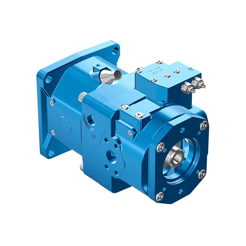
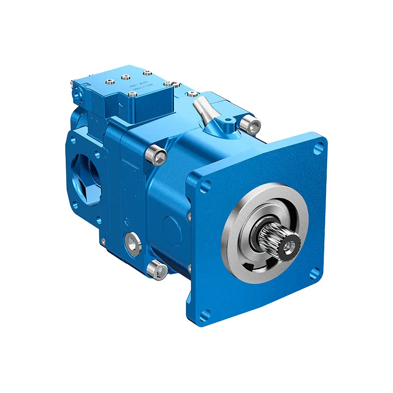
A11VO Open Circuit Variable Piston Pump
The A11VO variable pump is offered for open-circuit mobile hydraulics. Its family documentation includes A11VO and charged A11VLO arrangements, so speed and inlet conditions must be attached to the actual version rather than combined into one family maximum.
- Mobile-application focus
- Self-priming or charged arrangements
- Through-drive configuration available
- Variable displacement and multiple controls
PRANCE HYDRAULIC · PRODUCT SERIES
A11VO Open Circuit Variable Piston Pump
Axial piston; variable swashplate · Open circuit
The A11VO variable pump is offered for open-circuit mobile hydraulics. Its family documentation includes A11VO and charged A11VLO arrangements, so speed and inlet conditions must be attached to the actual version rather than combined into one family maximum.
Model
✓
Request a QuotationTechnische Daten & Datenblatt anzeigenA11VOAxial piston; variable swashplate
Confirm the complete model and approved specification with Prance Hydraulic. Product-series references alone do not establish interchangeability.
Configuration review · Technical documentation · Product selection
Produktdetails
- Mobile-application focus
- Self-priming or charged arrangements
- Through-drive configuration available
- Variable displacement and multiple controls
CATEGORIES: Kolbenpumpe, Verstellpumpe
A11VO Features & Application
Mobile-application focus
Specify the full MS order code, installation drawing and operating duty so the quotation can identify the proposed configuration.
Self-priming or charged arrangements
Specify the full MS order code, installation drawing and operating duty so the quotation can identify the proposed configuration.
Through-drive configuration available
Review combined drive torque and simultaneous demand, including any additional pump connected to the drive.
Variable displacement and multiple controls
Match the complete control option and its command requirements to the existing controller. Similar housings can use different control arrangements.
A11VO Specifications
| Series / model | A11VO |
|---|---|
| Product type | A11VO Open Circuit Variable Piston Pump |
| Design | Axial piston; variable swashplate |
| Circuit / selection | Open circuit |
| Published family sizes | 40, 60, 75, 95, 130, 145, 190 and 260; version-dependent |
| Inlet arrangement | Confirm self-priming, pressurized tank or charged version |
A11VO Selection & Configuration
The A11VO variable pump is offered for open-circuit mobile hydraulics. Its family documentation includes A11VO and charged A11VLO arrangements, so speed and inlet conditions must be attached to the actual version rather than combined into one family maximum.
Review the required flow and power over the machine work cycle, including any pump mounted on the through drive. Specify the inlet arrangement, control and simultaneous auxiliary demand. Confirm whether the quoted unit is A11VO or A11VLO before applying a speed limit.
cURL Too many subrequests by single Worker invocation. To configure this limit, refer to https://developers.cloudflare.com/workers/wrangler/configuration/#limits.
cURL Too many subrequests by single Worker invocation. To configure this limit, refer to https://developers.cloudflare.com/workers/wrangler/configuration/#limits.
Hydraulic pumps · Hydraulic motors · Hydraulic valves
Send the MS nameplate, operating requirements and installation drawing for a configuration review before quoting.
- Model review — send the full model code or an existing nameplate photograph.
- Interface matching — confirm shaft, mounting flange, rotation and ports.
- Operating conditions — provide flow, pressure, speed, fluid and duty cycle.
- Documentation — request the relevant product data and drawings for your review.

A11VO Buying Guide
Use this sequence to prepare the A11VO configuration for review and quotation.
- Define required flow at the actual drive speed and continuous pressure.
- Identify peak pressure, duration and the work cycle.
- Confirm the selected displacement control and any auxiliary-drive requirement.
- Match rotation viewed from the shaft end, shaft, flange and ports.
- Review inlet conditions, drain routing and the installation envelope.
- Confirm fluid, viscosity, temperature, filtration and seals.
- Approve the complete model, control, drawing, quantity and delivery terms.
Selection, Documentation & Project Support

Selection Support
Learn more →Share your hydraulic circuit, operating point and installation requirements for a configuration discussion.
Flow · Pressure · Speed · Interfaces

Technical Resources
Learn more →Review product documentation, model codes and technical data before finalizing the specification.
Datasheets · Model codes · Drawings

Project Inquiries
Learn more →Send your required model, quantity, application and project requirements to discuss your inquiry.
Product inquiries · Configuration review
Configuration, Quantity & Delivery
Confirm the complete MS code, approved drawing and operating limits. Availability, quantity, documentation and delivery date are confirmed in the quotation.
Discuss Your A11VO Application
Send the full model code, operating duty, installation details and quantity.
Request a A11VO QuotationA11VO Questions Before Ordering
What type of product is the A11VO?
A11VO Open Circuit Variable Piston Pump. Design: Axial piston; variable swashplate. Open circuit. Confirm the complete order code for the offered version.
Can a similar pump replace the A11VO?
cURL Too many subrequests by single Worker invocation. To configure this limit, refer to https://developers.cloudflare.com/workers/wrangler/configuration/#limits.
cURL Too many subrequests by single Worker invocation. To configure this limit, refer to https://developers.cloudflare.com/workers/wrangler/configuration/#limits
Define required flow at the actual drive speed and continuous pressure. Identify peak pressure, duration and the work cycle. Attach the nameplate, complete order code, installation drawing and required quantity.
A11VO Technical Data & Documents
View A11VO catalog data and operating conditions
cURL Too many subrequests by single Worker invocation. To configure this limit, refer to https://developers.cloudflare.com/workers/wrangler/configuration/#limits.
Technische Daten
Wertetabelle (theoretische Werte, ohne Wirkungsgrad und Toleranzen; Werte gerundet)
| Größe | A11VO | 40 | 60 | 75 | 95 | 130 | 190 | 190 | 260 | |
| Verschiebung | Vg Max | cm3 | 42 | 58.5 | 74 | 93.5 | 130 | 190 | 190 | 260 |
| Vg min. | cm3 | 0 | 0 | 0 | 0 | 0 | 0 | 0 | 0 | |
| Geschwindigkeit | ||||||||||
| Maximum bei Vg Max1) Maximum bei Vg ≤ Vg Max1) | nMax | U/min | 3000 | 2700 | 2550 | 2350 | 2100 | 2200 | 2100 | 1800 |
| nmax1 | U/min | 3500 | 3250 | 3000 | 2780 | 2500 | 2500 | 2100 | 2300 | |
| Verdrehsteifigkeit | Z-Welle | Nm/rad | 88894 | 102440 | 145836 | 199601 | 302495 | 302495 | 346190 | 686465 |
| P-Welle | Nm/rad | 87467 | 107888 | 143104 | 196435 | 312403 | 312403 | 383292 | 653835 | |
| S-Schaft | Nm/rad | 58347 | 86308 | 101921 | 173704 | 236861 | 236861 | 259773 | 352009 | |
| T-Welle | Nm/rad | 74476 | 102440 | 12560 | – | – | – | 301928 | 567115 | |
| Trägheitsmoment der Drehgruppe | JTW | Kgm2 | 0.0048 | 0.0082 | 0.0115 | 0.0173 | 0.0318 | 0.0341 | 0.055 | 0.0878 |
| Maximale Winkelbeschleunigung4) | α | rad/s2 | 22000 | 17500 | 15000 | 13000 | 10500 | 9000 | 6800 | 4800 |
| Füllmenge | V | I | 1.1 | 1.35 | 1.85 | 2.1 | 2.9 | 2.9 | 3.8 | 4.6 |
| Masse (ca.) | m | kg | 32 | 40 | 45 | 53 | 66 | 76 | 95 | 125 |
| Größe | A11VO | 130 | 145 | 190 | 260 | |
| Verschiebung | Vg Max | cm3 | 130 | 145 | 193 | 260 |
| Vg min. | cm3 | 0 | 0 | 0 | 0 | |
| Geschwindigkeit | ||||||
| Maximum bei Vg Max1) Maximum bei Vg ≤ Vg Max1) | nMax | U/min | 2500 | 2500 | 2500 | 2300 |
| nmax1 | U/min | 2500 | 2500 | 2500 | 2300 | |
| Verdrehsteifigkeit | Z-Welle | Nm/rad | 302495 | 302495 | 346190 | 686465 |
| P-Welle | Nm/rad | 312403 | 312403 | 383292 | 653835 | |
| S-Schaft | Nm/rad | 236861 | 236861 | 259773 | 352009 | |
| T-Welle | Nm/rad | – | – | 301928 | 567115 | |
| Trägheitsmoment der Drehgruppe | JTW | Kgm2 | 0.0337 | 0.036 | 0.0577 | 0.0895 |
| Maximale Winkelbeschleunigung4) | α | rad/s2 | 10500 | 9000 | 6800 | 4800 |
| Füllmenge | V | I | 2.9 | 2.9 | 3.8 | 4.6 |
| Masse (ca.) | m | kg | 72 | 73 | 104 | 138 |
Zulässige Radial- und Axialbelastung der Antriebswelle
Die angegebenen Werte sind Höchstwerte und für den Dauerbetrieb nicht zulässig.| Größe | 40 | 60 | 75 | 95 | 130 | 190 | 190 | 260 | ||
| Radiale Kraft, max. im Abstand a, b, c (vom Wellenbund) | FQ-max a | N mm | 3600 | 5000 | 6300 | 8000 | 11000 | 11000 | 16925 | 22000 |
| 17.5 | 17.5 | 20 | 20 | 22.5 | 22.5 | 26 | 29 | |||
| FQ-max b | N mm | 2891 | 4046 | 4950 | 6334 | 8594 | 8594 | 13225 | 16809 | |
| 30 | 30 | 35 | 35 | 40 | 40 | 46 | 50 | |||
| FQ-max c | N mm | 2416 | 3398 | 4077 | 5242 | 7051 | 7051 | 108500 | 13600 | |
| 42.5 | 42.5 | 50 | 50 | 57.5 | 57.5 | 66 | 71 | |||
| Axialkraft, max. | ±Fax max | N | 1500 | 2200 | 2750 | 3500 | 4800 | 4800 | 6000 | 4150 |
Zulässige Eingangs- und Durchtriebsdrehmomente
| Größe | 40 | 60 | 75 | 95 | 130 | 190 | 190 | 260 | ||
| Eingangsdrehmoment, max.2) at shaft end P Shaft key DN 6885 | ||||||||||
| TDauerwelle. | Machs gut | 468 | 648 | 824 | 1044 | 1448 | 1448 | 2226 | 2787 | |
| Ø 32 | Ø 35 | Ø 40 | Ø 45 | Ø 50 | Ø 50 | Ø 55 | Ø 60 | |||
| at Z shaft end DIN 5480 | TDauerwelle. | Machs gut | 912 | 912 | 1460 | 2190 | 3140 | 3140 | 3140 | 5780 |
| W35 | W35 | W40 | W45 | W50 | W50 | W50 | W60 | |||
| at S shaft end ANSI B92.1a-1976 (SAE J744) | TDauerwelle. | Machs gut | 314 | 602 | 602 | 1640 | 1640 | 1640 | 1640 | 1640 |
| 1 in | 1 1/4 Zoll | 1 1/4 Zoll | 1 3/4 Zoll | 1 3/4 Zoll | 1 3/4 Zoll | 1 3/4 Zoll | 1 3/4 Zoll | |||
| at T shaft end ANSI B92.1a-1976 (SAE J744) | TDauerwelle. | Machs gut | 602 | 970 | 970 | – | – | – | 2670 | 4070 |
| 1 1/4 Zoll | 1 3/8 Zoll | 1 3/8 Zoll | – | – | – | 2 in | 2 1/4 Zoll | |||
| Durch das Antriebsdrehmoment, max.3) | TDauerwelle. | Machs gut | 314 | 521 | 660 | 822 | 1110 | 1110 | 1760 | 2065 |
Drehmomentverteilung
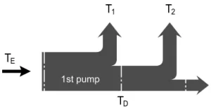
Bestimmung des Nennwerts
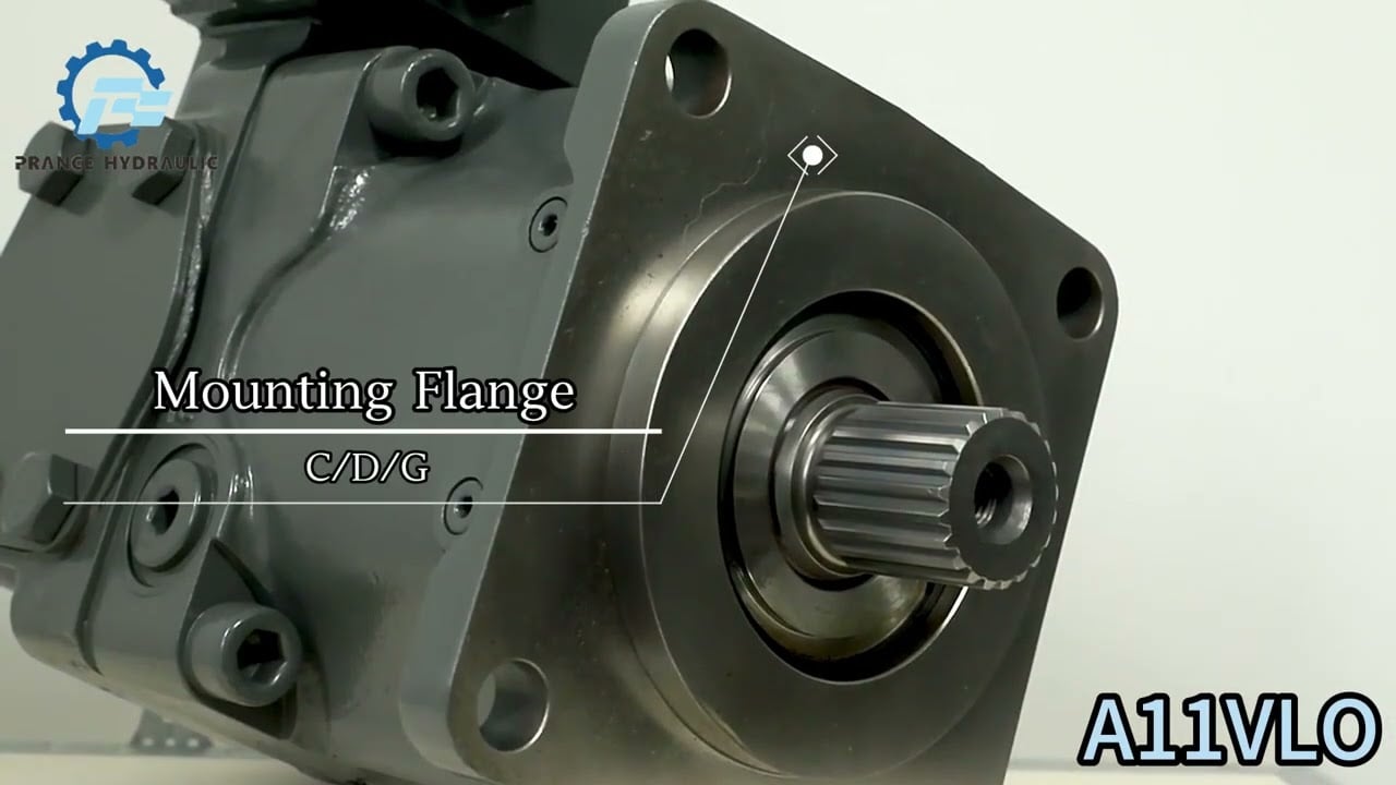
Watch A11VO Product Video
Related Selection Resources
Request a A11VO Quotation
Tell us your required configuration, quantity and application.
Ähnliche Produkte
Compare related hydraulic pumps and confirm the complete configuration for your application.


Bestellnummer / Standardprogramm
| A11V | ○ | / | 1 | - | N | ||||||||||||
| 01 | 02 | 03 | 04 | 05 | 06 | 07 | 08 | 09 | 10 | 11 | 12 | 13 | 14 | 15 | 16 |
Axialkolbeneinheit
| 01 | Schrägscheibenbauweise, verstellbar, Nenndruck 350 bar, Maximaldruck 400 bar | A11V |
Ladepumpe (Laufrad)
| 02 | ohne Ladepumpe | ● | ● | ● | ● | ● | ● | ● | ● | |
| mit Ladungspumpe | - | - | - | - | ● | ● | ● | ● | L |
Operation
| 03 | Pumpe, offener Kreisklauf | ○ |
Größe
| 04 | ≈Verschiebung Yg Maxin cm3 | 40 | 60 | 75 | 95 | 130 | 145 | 190 | 260 |
Steuergerät
| 05 | Leistungsregelung | LR | ● | ● | ● | ● | ● | ● | ● | ● | LR | |||||||
| mit Überschreibung | Kreuzabtastung | negativ | LR | C | ● | ● | ● | ● | ● | ● | ● | ● | LP.C | |||||
| im Zusammenhang mit Hochdruck | negativ | LR3 | ● | ● | ● | ● | ● | ● | ● | ● | LR3 | |||||||
| pilotdruckabhängig | negativ | LG1 | ● | ● | ● | ● | ● | ● | ● | ● | LG1 | |||||||
| positiv | LG2 | ● | ● | ● | ● | ● | ● | ● | ● | LG2 | ||||||||
| elektrisch | U=12V | negativ | LE1 | ○ | ○ | ○ | ● | ● | ● | ● | ● | LE1 | ||||||
| U=24V | negativ | LE2 | ○ | ● | ● | ● | ● | ● | ● | ● | LE2 | |||||||
| mit Abschaltvorrichtung | D | ● | ● | ● | ● | ● | ● | ● | ● | L.D. | ||||||||
| hydraulisch, 2-stufig | E | ● | ● | ● | ● | ● | ● | ● | ● | L.E. | ||||||||
| hydraulisch, ferngesteuert | G | ● | ● | ● | ● | ● | ● | ● | ● | Liebe Grüße. | ||||||||
| mit Lasterfassung | S | ● | ● | ● | ● | ● | ● | ● | ● | L...S | ||||||||
| elektrisch, man. Übersteuerung, 24 V | S2 | ○ | ○ | ○ | ● | ● | ● | ● | ● | L...S2 | ||||||||
| hydraulisch, Propellerverstellung | S5 | ○ | ○ | ○ | ● | ● | ● | ● | ● | L...S5 | ||||||||
| mit Hubbegrenzung | negativ
charakteristisch |
Δp = 25 bar | H1 | ● | ● | ● | ● | ● | ● | ● | ● | L...H1 | ||||||
| Δp = 10 bar | H5 | ● | ● | ● | ● | ● | ● | ● | ● | L...H5 | ||||||||
| positiv
charakteristisch |
Δp = 25 bar | H2 | ● | ● | ● | ● | ● | ● | ● | ● | L...H2 | |||||||
| Δp = 10 bar | H6 | ● | ● | ● | ● | ● | ● | ● | ● | L...H6 | ||||||||
| U=12V | U1 | ● | ● | ● | ● | ● | ● | ● | ● | L...U1 | ||||||||
| U=24V | U2 | ● | ● | ● | ● | ● | ● | ● | ● | L...U2 | ||||||||
| Druckregelung | DR | ● | ● | ● | ● | ● | ● | ● | ● | DR | ||||||||
| mit Lasterfassung | DRS | ● | ● | ● | ● | ● | ● | ● | ● | DRS | ||||||||
| ferngesteuert | DRG | ● | ● | ● | ● | ● | ● | ● | ● | DRG | ||||||||
| für den Parallelbetrieb | DRL | ● | ● | ● | ● | ● | ● | ● | ● | DRL | ||||||||
| Hydrauliksteuerung, vorsteuerdruckabhängig | positive Eigenschaft | Δp = 10 bar | HD1 | ● | ● | ● | ● | ● | ● | ● | ● | HD1 | ||||||
| Δp = 25 bar | HD2 | ● | ● | ● | ● | ● | ● | ● | ● | HD2 | ||||||||
| mit Abschaltvorrichtung | D | ● | ● | ● | ● | ● | ● | ● | ● | HD.D | ||||||||
| mit Druckabschaltung, ferngesteuert | G | ○ | ● | ○ | ○ | ○ | ○ | ● | ● | HD.G | ||||||||
| Elektrische Steuerung mit Proportionalmagnet | positive Eigenschaft | U=12V EP1 | ● | ● | ● | ● | ● | ● | ● | ● | EP1 | |||||||
| U=24V EP2 | ● | ● | ● | ● | ● | ● | ● | ● | EP2 | |||||||||
| mit Abschaltvorrichtung | D | ● | ● | ● | ● | ● | ● | ● | ● | EP.D | ||||||||
| mit Druckabschaltung, Fernbedienung | G | ● | ● | ● | ● | ● | ● | ● | ● | EP.G | ||||||||
Bei Steuerungen mit mehreren Zusatzfunktionen ist die Reihenfolge der Spalten zu beachten, pro Spalte ist nur eine Option möglich (z. B. LRDCH2). Folgende Kombinationen sind für die Leistungssteuerung nicht verfügbar: LRDS2, LRDS5, L.. GS, L.. GS2, L. GS5EC sowie die Kombination L..DG in Verbindung mit den Hubbegrenzern H1, H2, H5, H6, U1 und U2.
Serie
| 06 | 1 |
Index
| 07 | Größe 40 ... 130 | 0 |
| Größe 145...260 | 1 |
Drehrichtung
| 08 | Ansicht vom Wellenende | im Uhrzeigersinn | R |
| gegen den Uhrzeigersinn | L |
Robben
| 09 | NBR (Nitrilkautschuk), Wellendichtring aus FKM (Fluororobkautschuk) | N |
Wellenende
| 10 | 40 | 60 | 75 | 95 | 130 | 145 | 190 | 260 | |||
| Verzahnte Welle DIN 5480 für Einzel- und Kombipumpe | ● | ● | ● | ● | ● | ● | ● | ● | Z | ||
| Welle mit Passfeder DIN 6885 | ● | ● | ● | ● | ● | ● | ● | ● | P | ||
| Keilwelle ANSI B92.1a-1976 | für eine einzelne Pumpe | ● | ● | ● | ● | ● | ● | ● | ● | S | |
| für Kombipumpe | ● | ● | ● | _1) | _1) | _1) | ● | ● | T | ||
Montageflansch
| 11 | 40 | 60 | 75 | 95 | 130 | 145 | 190 | 260 | ||
| SAE-J744-2-Loch | ● | ● | - | - | - | - | - | - | C | |
| SAE J744 4-Loch | - | - | ● | ● | ● | ● | ● | ● | D | |
| SAE J6172) (SAE 3) | - | - | - | ● | ● | ● | ● | - | G |
Servicetüranschlüsse
| 12 | Druck- und Sauganschluss SAE, seitlich, gegenüberliegend
(mit metrischen Befestigungsgewinden) |
40 | 60 | 75 | 95 | 130 | 145 | 190 | 260 | |
| ● | ● | ● | ● | ● | ● | ● | ● | 12 |
Durchfahrt
| 40 | 60 | 75 | 95 | 130 | 145 | 190 | 260 | |||||||
| 13 | SAE-J744-Flansch3) | Kupplung für Keilwelle | ||||||||||||
| - | - | ● | ● | ● | ● | ● | ● | ● | ● | N00 | ||||
| 82-2 | (A) | 5/8 Zoll | 9T 16/32DP | (A) | ● | ● | ● | ● | ● | ● | ● | ● | K01 | |
| 3/4 Zoll | 11Z 16/32DP | (A-B) | ○ | ● | ○ | ● | ● | ● | ○ | ○ | K52 | |||
| 101-2 | (B) | 7/8 Zoll | 13Z 16/32DP | (B) | ● | ● | ● | ● | ● | ● | ● | ● | K02 | |
| 1 in | 15Z 16/32DP | (B-B) | ● | ● | ● | ● | ● | ● | ● | ● | K04 | |||
| W35 | 2x30x16x9g | ● | ● | ● | ● | ● | ● | ● | ● | K79 | ||||
| 127-2 | (C)4) | 1 1/4 Zoll | 14Z 12/24DP | (C) | - | ● | ● | ● | ● | ● | ● | ● | K07 | |
| 1 1/2 Zoll | 17T 12/24DP | (C-C) | - | - | - | ● | ● | ● | ● | ● | K24 | |||
| W30 | 2x30x14x9g | - | ● | ● | ● | ● | ● | ● | ● | K80 | ||||
| W35 | 2x30x16x9g | - | ● | ● | ● | ● | ● | ● | ● | K61 | ||||
| 152-4 | (D) | 1 1/4 Zoll | 14Z 12/24DP | (C) | - | - | ● | ● | ● | ● | ● | ● | K86 | |
| 1 3/4 Zoll | 13T 8/16DP | (D) | - | - | - | - | ● | ● | ● | ● | K17 | |||
| W40 | 2x30x18x9g | - | - | ● | ● | ● | ● | ● | ● | K81 | ||||
| W45 | 2x30x21x9g | - | - | - | ● | ● | ● | ● | ● | K82 | ||||
| W50 | 2x30x24x9g | - | - | - | - | ● | ● | ● | ● | K83 | ||||
| 165-4 | (E) | 1 3/4 Zoll | 13T 8/16DP | (D) | - | - | - | - | - | - | ● | ● | K72 | |
| W50 | 2x30x24x9g | - | - | - | - | - | - | ● | ● | K84 | ||||
| W60 | 2x30x28x9g | - | - | - | - | - | - | - | ● | K67 | ||||
Schwenkwinkelanzeiger
| 14 | 40 | 60 | 75 | 95 | 130 | 145 | 190 | 260 | ||
| ohne Schwenkwinkelanzeige (kein Symbol) | ● | ● | ● | ● | ● | ● | ● | ● | ||
| mit optischer Schwenkwinkelanzeige | ● | - | ● | ● | ● | ● | ● | ● | v | |
| mit elektrischem Schwenkwinkelsensor | ● | - | ● | ● | ● | ● | ● | ● | R |
Magnetstecker
| 15 | 40 | 60 | 75 | 95 | 130 | 145 | 190 | 260 | ||
| DEUTSCH-Stecker umspritzt, 2-polig – ohne Löschdiode | ● | ● | ● | ● | ● | ● | ● | ● | P |
Standard-/Spezialversion
| 16 | Standardversion | ohne Symbol | |
| kombiniert mit Anbauteil oder Anbaupumpe | -K | ||
| Sonderversion | -S | ||
| kombiniert mit Anbauteil oder Anbaupumpe | -SK |
1) S-Welle geeignet für Kombinationspumpe!
2) Zum Einpassen in das Schwungradgehäuse des Verbrennungsmotors
3) 22-Loch; 44-Loch
4) Größe 190 und 260 mit 2 + 4-Loch-Flansch
• = verfügbar ○ = auf Anfrage - = nicht verfügbar  = bevorzugtes Programm
Technische Daten
Wertetabelle (theoretische Werte, ohne Wirkungsgrad und Toleranzen; Werte gerundet)
| Größe | A11VO | 40 | 60 | 75 | 95 | 130 | 190 | 190 | 260 | |
| Verschiebung | Vg Max | cm3 | 42 | 58.5 | 74 | 93.5 | 130 | 190 | 190 | 260 |
| Vg min. | cm3 | 0 | 0 | 0 | 0 | 0 | 0 | 0 | 0 | |
| Geschwindigkeit | ||||||||||
| Maximum bei Vg Max1)
Maximum bei Vg ≤ Vg Max1) |
nMax | U/min | 3000 | 2700 | 2550 | 2350 | 2100 | 2200 | 2100 | 1800 |
| nmax1 | U/min | 3500 | 3250 | 3000 | 2780 | 2500 | 2500 | 2100 | 2300 | |
| Fluss
bei nMax und vG-Max |
qv max | l/min | 126 | 158 | 289 | 220 | 273 | 319 | 405 | 468 |
| Ablauf bei
qv Max und Δp = 350 bar |
PMax | kW | 74 | 92 | 110 | 128 | 159 | 186 | 236 | 273 |
| Drehmoment bei
vg Max und Δp = 350 bar |
TMax | Machs gut | 234 | 326 | 412 | 521 | 724 | 808 | 1075 | 1448 |
| Verdrehsteifigkeit | Z-Welle | Nm/rad | 88894 | 102440 | 145836 | 199601 | 302495 | 302495 | 346190 | 686465 |
| P-Welle | Nm/rad | 87467 | 107888 | 143104 | 196435 | 312403 | 312403 | 383292 | 653835 | |
| S-Schaft | Nm/rad | 58347 | 86308 | 101921 | 173704 | 236861 | 236861 | 259773 | 352009 | |
| T-Welle | Nm/rad | 74476 | 102440 | 12560 | - | - | - | 301928 | 567115 | |
| Trägheitsmoment der Drehgruppe | JTW | Kgm2 | 0.0048 | 0.0082 | 0.0115 | 0.0173 | 0.0318 | 0.0341 | 0.055 | 0.0878 |
| Maximale Winkelbeschleunigung4) | α | rad/s2 | 22000 | 17500 | 15000 | 13000 | 10500 | 9000 | 6800 | 4800 |
| Füllmenge | V | I | 1.1 | 1.35 | 1.85 | 2.1 | 2.9 | 2.9 | 3.8 | 4.6 |
| Masse (ca.) | m | kg | 32 | 40 | 45 | 53 | 66 | 76 | 95 | 125 |
| Größe | A11VO | 130 | 145 | 190 | 260 | |
| Verschiebung | Vg Max | cm3 | 130 | 145 | 193 | 260 |
| Vg min. | cm3 | 0 | 0 | 0 | 0 | |
| Geschwindigkeit | ||||||
| Maximum bei Vg Max1)
Maximum bei Vg ≤ Vg Max1) |
nMax | U/min | 2500 | 2500 | 2500 | 2300 |
| nmax1 | U/min | 2500 | 2500 | 2500 | 2300 | |
| Fluss
bei nMax und vG-Max |
qv max | l/min | 325 | 363 | 483 | 598 |
| Ablauf bei
qv Max und Δp = 350 bar |
PMax | kW | 190 | 211 | 281 | 349 |
| Drehmoment bei
vg Max und Δp = 350 bar |
TMax | Machs gut | 724 | 808 | 1075 | 1448 |
| Verdrehsteifigkeit | Z-Welle | Nm/rad | 302495 | 302495 | 346190 | 686465 |
| P-Welle | Nm/rad | 312403 | 312403 | 383292 | 653835 | |
| S-Schaft | Nm/rad | 236861 | 236861 | 259773 | 352009 | |
| T-Welle | Nm/rad | - | - | 301928 | 567115 | |
| Trägheitsmoment der Drehgruppe | JTW | Kgm2 | 0.0337 | 0.036 | 0.0577 | 0.0895 |
| Maximale Winkelbeschleunigung4) | α | rad/s2 | 10500 | 9000 | 6800 | 4800 |
| Füllmenge | V | I | 2.9 | 2.9 | 3.8 | 4.6 |
| Masse (ca.) | m | kg | 72 | 73 | 104 | 138 |
1) Die Werte gelten bei absolutem Druck (PABS) 1 bar am Sauganschluss S und Mineralhydraulikflüssigkeit.
2) Die Werte gelten bei absolutem Druck (PABS) von mindestens 0,8 bar am Sauganschluss S und Mineralhydraulikflüssigkeit.
3) Die Werte gelten bei Vs Vg max oder im Falle einer Erhöhung des Eingangsdrucks PABS am Saugstutzen S (siehe Abbildung Seite 6)
4) – Der Gültigkeitsbereich liegt zwischen 0 und der maximal zulässigen Drehzahl. Er gilt für externe Anregungen (z. B. Motor 2-8fache Drehfrequenz, Kardanwelle doppelte Drehfrequenz).
-Der Grenzwert gilt nur für eine einzelne Pumpe.
-Die Belastung der Verbindungsteile muss berücksichtigt werden.
Achtung:
Das Überschreiten der zulässigen Grenzwerte kann zum Funktionsverlust, zu einer verkürzten Lebensdauer oder zur Zerstörung der Axialkolbeneinheit führen. Die zulässigen Werte können durch Berechnung ermittelt werden.
Zulässige Radial- und Axialbelastung der Antriebswelle
Die angegebenen Werte sind Höchstwerte und für den Dauerbetrieb nicht zulässig.
| Größe | 40 | 60 | 75 | 95 | 130 | 190 | 190 | 260 | ||
| Radiale Kraft, max. im Abstand a, b, c (vom Wellenbund)
|
FQ-max
a |
N
mm |
3600 | 5000 | 6300 | 8000 | 11000 | 11000 | 16925 | 22000 |
| 17.5 | 17.5 | 20 | 20 | 22.5 | 22.5 | 26 | 29 | |||
| FQ-max
b |
N
mm |
2891 | 4046 | 4950 | 6334 | 8594 | 8594 | 13225 | 16809 | |
| 30 | 30 | 35 | 35 | 40 | 40 | 46 | 50 | |||
| FQ-max
c |
N
mm |
2416 | 3398 | 4077 | 5242 | 7051 | 7051 | 108500 | 13600 | |
| 42.5 | 42.5 | 50 | 50 | 57.5 | 57.5 | 66 | 71 | |||
| Axialkraft, max.
|
±Fax max | N | 1500 | 2200 | 2750 | 3500 | 4800 | 4800 | 6000 | 4150 |
Zulässige Eingangs- und Durchtriebsdrehmomente
| Größe | 40 | 60 | 75 | 95 | 130 | 190 | 190 | 260 | ||
| Drehmoment
(bei Vg max. und Δp = 350 bar 1) |
TMax | Machs gut | 234 | 326 | 412 | 521 | 724 | 808 | 1075 | 1448 |
| Eingangsdrehmoment, max.2)
am Wellenende P Paßfeder DIN 6885 |
||||||||||
| TDauerwelle. | Machs gut | 468 | 648 | 824 | 1044 | 1448 | 1448 | 2226 | 2787 | |
| Ø 32 | Ø 35 | Ø 40 | Ø 45 | Ø 50 | Ø 50 | Ø 55 | Ø 60 | |||
| am Z-Wellenende
DIN 5480 |
TDauerwelle. | Machs gut | 912 | 912 | 1460 | 2190 | 3140 | 3140 | 3140 | 5780 |
| W35 | W35 | W40 | W45 | W50 | W50 | W50 | W60 | |||
| am S-Wellenende
ANSI B92.1a-1976 (SAE J744) |
TDauerwelle. | Machs gut | 314 | 602 | 602 | 1640 | 1640 | 1640 | 1640 | 1640 |
| 1 in | 1 1/4 Zoll | 1 1/4 Zoll | 1 3/4 Zoll | 1 3/4 Zoll | 1 3/4 Zoll | 1 3/4 Zoll | 1 3/4 Zoll | |||
| am T-Wellenende
ANSI B92.1a-1976 (SAE J744) |
TDauerwelle. | Machs gut | 602 | 970 | 970 | - | - | - | 2670 | 4070 |
| 1 1/4 Zoll | 1 3/8 Zoll | 1 3/8 Zoll | - | - | - | 2 in | 2 1/4 Zoll | |||
| Durch das Antriebsdrehmoment, max.3) | TDauerwelle. | Machs gut | 314 | 521 | 660 | 822 | 1110 | 1110 | 1760 | 2065 |
1) Effizienz nicht berücksichtigt
2) Für Gelenkwellen ohne Radialkraft
3) Max. Eingangsdrehmoment für Welle S beachten!
Drehmomentverteilung
Bestimmung des Nennwerts
| Fluss | qv=(Vg ∙ n ∙ ηv) / 1000 | l/min |
| Drehmoment | T=(Vg ∙ Δp) / 20 ∙ π ∙ ηmh | Machs gut |
| Macht | P=(2π ∙ T ∙ n)/60000=(qv ∙ Δp)/600 ∙ ηt | kW |
Vg = Hubvolumen pro Umdrehung in cm³3
Δp = Differenzdruck in bar
n = Drehzahl in U/min
ηv = Volumetrischer Wirkungsgrad
ηmh Mechanisch-hydraulischer Wirkungsgrad
ηt = Gesamtwirkungsgrad (nt= nv* nmh)
