Wenzhou Prance Hydraulic Equipment Co., Ltd.

cURL Too many subrequests by single Worker invocation. To configure this limit, refer to https://developers.cloudflare.com/workers/wrangler/configuration/#limits
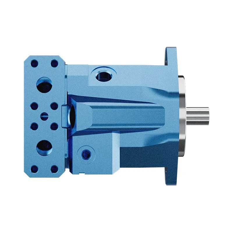
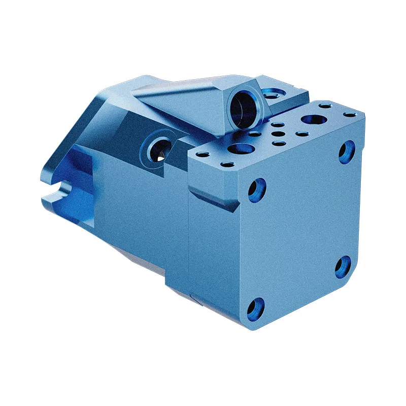
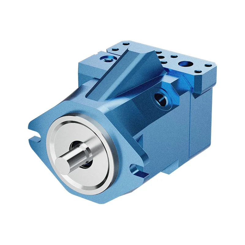
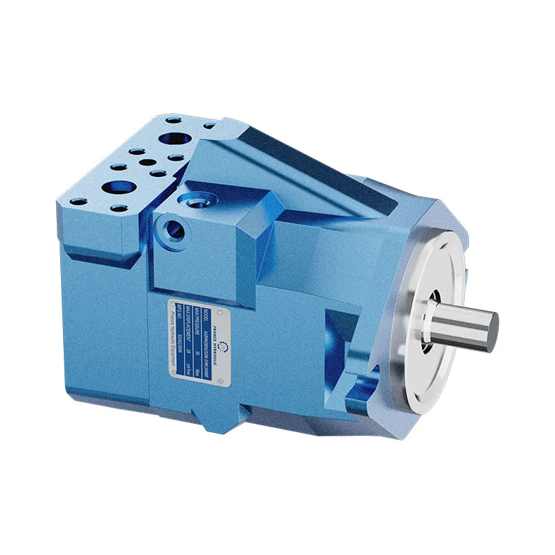
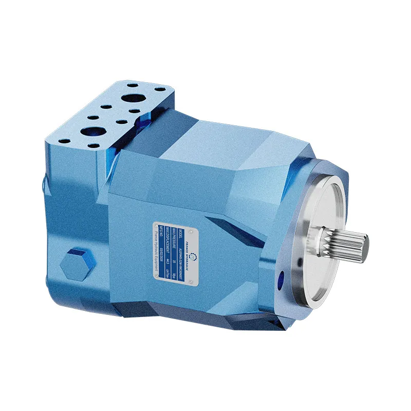
The A10VM variable displacement motor allows the torque-speed relationship to be changed through displacement. At the same flow, reducing displacement increases theoretical speed; at the same pressure difference it also reduces theoretical torque.
- Variable displacement A10 motor
- Output speed depends on flow and displacement
- Torque depends on pressure difference and displacement
- SAE two-bolt mounting reference
PRANCE HYDRAULIC · PRODUCT SERIES
cURL Too many subrequests by single Worker invocation. To configure this limit, refer to https://developers.cloudflare.com/workers/wrangler/configuration/#limits
Axial piston; swashplate variable displacement · Confirm open or closed circuit conditions
The A10VM variable displacement motor allows the torque-speed relationship to be changed through displacement. At the same flow, reducing displacement increases theoretical speed; at the same pressure difference it also reduces theoretical torque.
Model
✓
Request a QuotationTechnische Daten & Datenblatt anzeigenA10VMAxial piston; swashplate variable displacement
Confirm the complete model and approved specification with Prance Hydraulic. Product-series references alone do not establish interchangeability.
Configuration review · Technical documentation · Product selection
Produktdetails
- Variable displacement A10 motor
- Output speed depends on flow and displacement
- Torque depends on pressure difference and displacement
- SAE two-bolt mounting reference
CATEGORIES: Kolbenmotor, Verstellbarer Kolbenmotor
A10VM Features & Application
Variable displacement A10 motor
Specify the displacement range or switching arrangement and verify performance at each required setting.
Output speed depends on flow and displacement
Keep continuous, intermittent and peak conditions separate. Use the row for the selected size and configuration.
Torque depends on pressure difference and displacement
Keep continuous, intermittent and peak conditions separate. Use the row for the selected size and configuration.
SAE two-bolt mounting reference
Check pilot diameter, bolt pattern, shaft engagement or port pattern against the approved installation drawing.
A10VM Specifications
| Series / model | A10VM |
|---|---|
| Product type | cURL Too many subrequests by single Worker invocation. To configure this limit, refer to https://developers.cloudflare.com/workers/wrangler/configuration/#limits |
| Design | Axial piston; swashplate variable displacement |
| Circuit / selection | Confirm open or closed circuit conditions |
| Hubregelung | Variable |
| Mounting reference | SAE two-bolt flange in the existing description |
A10VM Selection & Configuration
The A10VM variable displacement motor allows the torque-speed relationship to be changed through displacement. At the same flow, reducing displacement increases theoretical speed; at the same pressure difference it also reduces theoretical torque.
Define the required displacement range and its control behavior before selecting the motor. Check the highest commanded speed and the torque available at minimum displacement, then match the SAE flange, shaft, ports and drain arrangement to the installation.
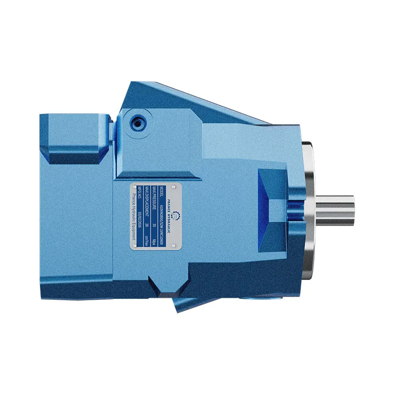
cURL Too many subrequests by single Worker invocation. To configure this limit, refer to https://developers.cloudflare.com/workers/wrangler/configuration/#limits.
cURL Too many subrequests by single Worker invocation. To configure this limit, refer to https://developers.cloudflare.com/workers/wrangler/configuration/#limits.
Hydraulic pumps · Hydraulic motors · Hydraulic valves
Send the MS nameplate, operating requirements and installation drawing for a configuration review before quoting.
- Model review — send the full model code or an existing nameplate photograph.
- Interface matching — confirm shaft, mounting flange, rotation and ports.
- Operating conditions — provide flow, pressure, speed, fluid and duty cycle.
- Documentation — request the relevant product data and drawings for your review.

A10VM Buying Guide
Use this sequence to prepare the A10VM configuration for review and quotation.
- Define starting and continuous torque, speed range and duty cycle.
- Specify available flow, work-port pressure difference and return pressure.
- Confirm the displacement setting and required behavior during starting and stopping.
- Check shaft, mounting pilot, flange, port orientation and external loads.
- Review case drainage, replenishment and any displacement control.
- Specify fluid conditions and any independent braking requirement.
- Approve the complete model, operating envelope, drawing and quantity.
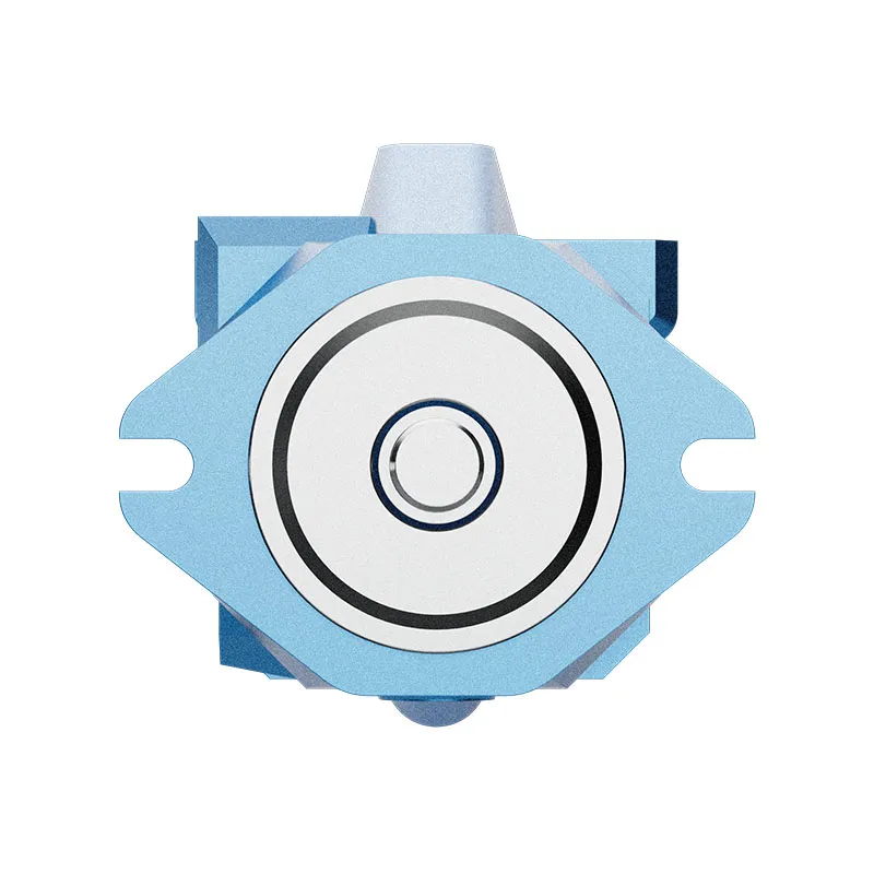
Selection, Documentation & Project Support

Selection Support
Learn more →Share your hydraulic circuit, operating point and installation requirements for a configuration discussion.
Flow · Pressure · Speed · Interfaces

Technical Resources
Learn more →Review product documentation, model codes and technical data before finalizing the specification.
Datasheets · Model codes · Drawings

Project Inquiries
Learn more →Send your required model, quantity, application and project requirements to discuss your inquiry.
Product inquiries · Configuration review
Configuration, Quantity & Delivery
Confirm the complete MS code, approved drawing and operating limits. Availability, quantity, documentation and delivery date are confirmed in the quotation.
Discuss Your A10VM Application
Send the full model code, operating duty, installation details and quantity.
Request a A10VM QuotationA10VM Questions Before Ordering
What type of product is the A10VM?
A10VM Variable Displacement Axial Piston Motor. Design: Axial piston; swashplate variable displacement. Confirm open or closed circuit conditions. Confirm the complete order code for the offered version.
Can a similar motor replace the A10VM?
cURL Too many subrequests by single Worker invocation. To configure this limit, refer to https://developers.cloudflare.com/workers/wrangler/configuration/#limits.
cURL Too many subrequests by single Worker invocation. To configure this limit, refer to https://developers.cloudflare.com/workers/wrangler/configuration/#limits
cURL Too many subrequests by single Worker invocation. To configure this limit, refer to https://developers.cloudflare.com/workers/wrangler/configuration/#limits.
A10VM Technical Data & Documents
View A10VM catalog data and operating conditions
cURL Too many subrequests by single Worker invocation. To configure this limit, refer to https://developers.cloudflare.com/workers/wrangler/configuration/#limits.
Technische Daten
Flüssig
Bitte beachten Sie vor der Projektplanung unsere Datenblätter RE 90220 (Mineralöl), RE 90221. (ecologically acceptable fluids) and RE90223(HF-fluids) for detailed information on fluids and application conditions. When operating on ecologically acceptable fluids, limitations to the technical data may be necessary. Please contact us and state the fluid used in clear text when ordering.Betriebsviskositätsbereich
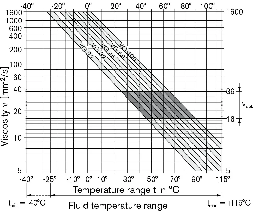
For optimum efficiency and service life we recommend an ope-rating viscosity (at operating temperature) in the range νentscheiden = opt. operating viscosity 16…36 mm2/s referred to circuit temperature in closed circuits or tank temperature in open circuits. The following limits are valid for extreme operating conditions: Vmin.= 5 mm2/s (closed circuit) Vmin.= 10 mm2/s (open circuit) briefly (t≤ 1 min) at max. permissible temperature of 115℃. Please note, that the max. fluid temperature of 115℃ may also not be exceeded in certain areas (for instance bearing area) The temperature in the bearing area is approx. 5 K higher than the average fluid temperature. νMax= 1600 mm2/s briefly (t≤ 1 min) on cold start (tmin. = -25℃, p≤30 bar, n≤1000 rpm). At temperatures between -25 ℃ and -40 ℃ special measures may be required for certain installation positions. Please consult us for further information For detailed information on operation at very low temperatures see RE 90300-03-B.Hinweise zur Auswahl der Hydraulikflüssigkeit
In order to select the correct fluid, it is necessary to know the operating temperature in the tank (open circuit), circuit temperature (closed circuits), in relation to the ambient temperature. The fluid should be selected, so that within the operating temperature range, the viscosity lies within the optimum range(νentscheiden), see shaded section of the selection diagram. We recommend to select the higher viscosity grade in each case. Example: at an ambient temperature of X ℃ the operating temperature in the tank is 60℃.In the optimum viscosity range(νentscheiden; shaded area) this corresponds to viscosity grades VG 46 resp. VG 68; select VG 68. Important: The leakage fluid (case drain fluid) temperature is influenced by pressure and motor speed and is always higher than the tank temperature. However, at no point in the circuit may the temperature exceed 115 ℃. If it is not possible to comply with the above conditions because of extreme operating parameters or high ambient temperatures please consult usFluidfiltration
The finer the filtration the better the achieved cleanliness of the fluid and the longer the life of the axial piston unit. To ensure a reliable functioning of the axial piston unit, a minimum cleanliness of 20/18/15 to ISO 4406 is necessary. At very high fluid temperatures (90℃ to max. 115℃) the minimum cleanliness has to be at least 19/17/14 to ISO 4406. If above cleanliness classes cannot be met please consult us.Betriebsdruckbereich
Pressure at port A or B (Pressure data to DIN 24312)| Nenndruck pN | 280 bar 1) |
| Maximaler Druck PMax | 350 bar |
| Bei in Reihe geschalteten Motoren bitten wir Sie, uns zu konsultieren. | |
| Max. zulässiger Druck am Leckölanschluss L | |
| PABS Maximaler Betrieb als Motor im Leerlauf | 4-Bar-ABS |
| PABS Maximalbetrieb als Motor im geschlossenen Kreis | 4-Bar-ABS |
| PABS Maximaler Motor-/Pumpenbetrieb im offenen Kreislauf | 2 bar abs |
| Drehrichtung, gesehen auf das Wellenende | |||||
| im Uhrzeigersinn | gegen den Uhrzeigersinn | ||||
| B zu A | Von A nach B | ||||
Auswahldiagramm
Wertestabelle(Theoretische Werte, ohne Wirkungsgrade und Toleranzen; Werte gerundet)
| Größe | 28 | 45 | 63 | 85 | |||
| Verschiebung | VG-Max | cm3 | 28 | 45 | 62 | 87 | |
| Vg-Moll | cm3 | 8 (VM)/10 (VE) | 12 | 16 | 22 | ||
| Geschwindigkeit1) | 4700 | 4000 | 3300 | 3100 | |||
| max. bei VG-Max | n0 max | min.-1 | |||||
| max. bei Vg-Moll | n0 max zul | min.-1 | 5400 | 4600 | 3900 | 3560 | |
| Mindestgeschwindigkeit im Dauerbetrieb | n0 Min. | min.-1 | 250 | 250 | 250 | 250 | |
| Einlassströmung | 131,6 | 180 | 205 | 270 | |||
| bei n0 max und VG-Max | qv0 Max | l/min | |||||
| Drehmomentkonstante2) bei VG-Max | TK | Nm/bar | 0,445 | 0,716 | 1,002 | 1,35 | |
| Drehmoment | 125 | 200 | 276 | 387 | |||
| bei VG-Max | PN= 280 bar | TMax | Machs gut | ||||
| Tatsächliches Anzugsdrehmoment | 92 | 149 | 205 | 253 | |||
| bei n = 0 min-1 | PN = 280 bar | T | nach ca. | ||||
| Verdrehsteifigkeit | Schacht R | c | Nm/rad | 26000 | 41000 | 69400 | 152900 |
| Welle W | c | Nm/rad | 19800 | 34400 | 54000 | 117900 | |
| Massenträgheitsmoment (bezogen auf die Abtriebswelle) | J | kgm2 | 0,0017 | 0,0033 | 0,0056 | 0,012 | |
| Füllmenge | V | L | 0,6 | 0,7 | 0,8 | 1,0 | |
| Gewicht ca. | m | kg | 14 | 18 | 26 | 34 | |
je nach Motordrehzahl
Größe berechnen
| Fluss | qv=(Vg∙n)/(1000∙ηv) | [l/min] | Vg= Verdrängung pro Umdrehung in cm³3 Δp=Differential pressure in bar n=speed in rpm ηv=Volumetric efficiency ηmh=Mechanical-hydraulic efficiency ηt= Gesamtwirkungsgrad (ηt = ηv ∙ηmhcURL Too many subrequests by single Worker invocation. To configure this limit, refer to https://developers.cloudflare.com/workers/wrangler/configuration/#limitsKDrehmomentkonstante |
| Drehmoment | T=(1,59∙Vg∙ Δp∙ηmh)/100 | [Nm] | |
| oder | T=Tk∙ Δp∙ηmh | ||
| Ausgangsleistung | P=(2π∙T∙n)/60000=(qv∙Δp∙ηt)/600 | [kW] | |
| Ausgabegeschwindigkeit | n=(qv∙1000∙ηv)/Vg | [min-1] | |
Zulässige Radial- und Axialkräfte an der Antriebswelle
| Größe | 28 | 45 | 63 | 85 | ||||
| Max. Radialkraft | 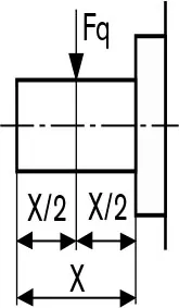 |
bei X/2 | FQ-max | N | 1200 | 1500 | 1700 | 2000 |
| Max. Axialkraft | 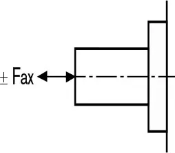 |
FAxt | N | 1000 | 1500 | 2000 | 3000 | |
cURL Too many subrequests by single Worker invocation. To configure this limit, refer to https://developers.cloudflare.com/workers/wrangler/configuration/#limits
Related Selection Resources
Request a A10VM Quotation
Tell us your required configuration, quantity and application.
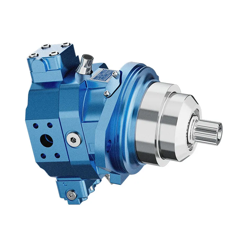
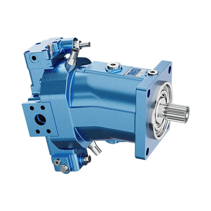
Ähnliche Produkte
Compare related hydraulic motors and confirm the complete configuration for your application.
Bestellnummer für Standardprogramm
| A10V | M | / | 52 | W | – | V | C | ||||||||
| 01 | 02 | 03 | 04 | 05 | 06 | 07 | 08 | 09 | 10 | 11 | 12 | 13 | 14 |
Axialkolbeneinheit
| 01 | Schrägscheibenbauweise, verstellbar, Nenndruck 280 bar, Maximaldruck 350 bar | A10V |
Betriebsart
| 02 | Motor, offener und geschlossener Stromkreis | M |
Größe (NG)
| 03 | Verdrängung VG-Max in cm3 | 028 | 045 | 063 | 085 |
Steuergeräte
| 028 | 045 | 063 | 085 | ||||||
| 04 | Zwei Punkt Steuerung |
Direktgesteuert, externe Steuermediumversorgung, ohne Vorsteuerventil | ● | ● | ● | ● | DG | ||
| hydraulisch betätigt | Streichelzeit | ohne | ● | ● | ● | ○ | HZ | ||
| Elektrisch mit Magnetventil | Öffnung | mit | ● | ● | ● | ○ | HZ6 | ||
| Elektrisch mit Magnetventil | Streichelzeit | ohne | ● | ● | ● | ● | EZ1 | ||
| Steuerspannung 12V | Öffnung | mit | ● | ● | ● | ● | EZ6 | ||
| Elektrisch mit Magnetventil | Streichelzeit | ohne | ● | ● | ● | ○ | EZ2 | ||
| Steuerspannung 24V | Öffnung | mit | ● | ● | ● | ○ | EZ7 | ||
Serie
| 05 | Serie 5, Index 2 | 52 |
Drehrichtung
| 06 | Mit Blick auf das Wellenende Bidirektional | W |
Mindestverschiebung
| 028 | 045 | 063 | 085 | ||||
| 07 | Vg-Moll (in cm3stufenlos verstellbar | von/bis | 8/28 | 12/25 | 16/38 | 22/50 | 1 |
| Anpassungszustand im Klartext | von/bis | – | 26/45 | 40/62 | 48/85 | 2 | |
Robben
| 08 | FKM (Fluor-Kautschuk) | V |
Antriebswelle
| 028 | 045 | 063 | 085 | |||
| 09 | Keilwelle nach ANSI B92.1 a-1976 für höheres Antriebsdrehmoment | ● | ● | ● | ● | R |
| Kerbverzahnte Welle, ANSI B92.1 a-1976, für reduziertes Antriebsdrehmoment | – | ● | ● | ● | W | |
Montageflansch
| 10 | SAE J744 2-Loch | C |
Anschlüsse für Versorgungsleitungen
| 11 | SAE-Flansche, seitlich auf derselben Seite, metrische Befestigungsschrauben | ● | ● | ● | ● | 10N00 | |||||
| SAE-Flansche hinten, metrische Befestigungsschrauben | ○ | ● | ○ | ○ | 11N00 | ||||||
| Gewindeanschlüsse seitlich, gleiche Seite, metrisches Gewinde | ● | ● | ● | ○ | 16N00 | ||||||
Ventile
| 12 | Ohne Ventile | ● | ● | ● | ● | 0 | |||||
| Integriebares Spülventil, nur mit seitlichen Anschlüssen (10N00 und 16N00) | ● | ● | ● | ● | 7 | ||||||
Geschwindigkeitsaufnahme
| 13 | Ohne Geschwindigkeitsabnahme | ● | ● | ● | ● | – | ||||
| Vorbereitet für induktiven Drehzahlabnehmer ID R | ● | ● | ● | ○ | D | |||||
Magnetstecker
| 14 | HIRSCHMANN - Steckverbinder — ohne Löschdiode | ▲ | ▲ | ▲ | ▲ | H | |||||
| DEUTSCH-Stecker, umspritzt, 2-polig — ohne Suppressordiode | ● | ● | ● | ● | P | ||||||
•=verfügbar ○=in Vorbereitung — =nicht verfügbar ▲=nicht für neue Projekte
| A10V | E | / | 52 | W | – | V | F | ||||||||
| 01 | 02 | 03 | 04 | 05 | 06 | 07 | 08 | 09 | 10 | 11 | 12 | 13 | 14 |
Axialkolbeneinheit
| 01 | Schrägscheibenbauweise, verstellbar, Nenndruck 280 bar, Maximaldruck 350 bar | A10v | |||||||
Betriebsart
| 02 | Motor, steckbar, offener und geschlossener Stromkreis | E | |||
Größe (NG)
| 03 | Verdrängung VG-Max in cm3 | 028 | 045 | 063 |
Steuergeräte
| 028 | 045 | 063 | ||||||
| 04 | Zwei Punkt Steuerung |
Direktgesteuert, externe Steuermediumversorgung, ohne Vorsteuerventil | ● | ● | ○ | DG | ||
| Hydraulisch | Streichelzeit | ohne | ● | ● | ● | HZ | ||
| Öffnung | mit | ● | ● | ● | HZ6 | |||
| Elektrisch mit Magnetventil | Streichelzeit | ohne | ● | ● | ● | EZ1 | ||
| Steuerspannung 12V | Öffnung | mit | ● | ● | ● | EZ6 | ||
| Elektrisch mit Magnetventil | Streichelzeit | ohne | ● | ● | ● | EZ2 | ||
| Steuerspannung 24V | Öffnung | mit | ● | ● | ● | EZ7 | ||
Serie
| 05 | Serie 5, Index 2 | 52 |
Drehrichtung
| 06 | Betrachtung vom Wellenende aus Bidirektional | W | ||||
Mindestverschiebung
| 028 | 045 | 063 | ||||
| 07 | Vg-Moll (in cm3) Stufenlos verstellbar | von/bis | 10/28 | 12/25 | 16/38 | 1 |
| Anpassung bitte im Klartext angeben | von/bis | – | 26/45 | 40/62 | 2 | |
Robben
| 08 | FKM (Fluor-Kautschuk) | V |
Antriebswelle
| 028 | 045 | 063 | |||||||
| 09 | Keilwelle nach ANSI B92.1 a-1976 für höheres Antriebsdrehmoment | ● | ● | ● | R | ||||
| Kerbverzahnte Welle, ANSI B92.1 a-1976, für reduziertes Antriebsdrehmoment | – | ● | ● | W | |||||
Montageflansch
| 10 | Spezial-2-Schrauben | F |
Anschlüsse für die Serviceleitung
| 11 | SAE-Flansche seitlich – gleiche Seite, metrische Befestigungsschrauben | ● | ● | ● | 10N00 | ||||
| SAE-Flansche hinten, metrische Befestigungsschrauben | ○ | ● | ○ | 11N00 | |||||
| Gewindeanschlüsse seitlich, gleiche Seite, metrisches Gewinde | ● | ● | ● | 16N00 | |||||
Ventile
| 12 | Ohne Ventile | ● | ● | ● | 0 | |||||
| Integriebares Spülventil, nur mit seitlichen Anschlüssen (10N00 und 16N00) | ● | ● | ● | 7 | ||||||
Geschwindigkeitsaufnahme
| 13 | Ohne Geschwindigkeitsabnahme | ● | ● | ● | – | ||||
| Vorbereitet für induktiven Drehzahlabnehmer ID R | ○ | ● | ○ | D | |||||
Magnetstecker
| 14 | HIRSCHMANN - Steckverbinder—ohne Entstördiode | ▲ | ▲ | ▲ | H | |||||
| DEUTSCH-Stecker, umspritzt, 2-polig—ohne Entstördiode | ● | ● | ● | P | ||||||
•=verfügbar ○=in Vorbereitung — =nicht verfügbar ▲=nicht für neue Projekte
Technische Daten
Flüssig
Bitte beachten Sie vor der Projektplanung unsere Datenblätter RE 90220 (Mineralöl), RE 90221. (ökologisch unbedenkliche Flüssigkeiten) und RE90223 (HF-Flüssigkeiten) für detaillierte Informationen zu Flüssigkeiten und Anwendungsbedingungen.
Beim Betrieb mit ökologisch vertretbaren Medien können Einschränkungen der technischen Daten erforderlich sein.
Bitte kontaktieren Sie uns bei der Bestellung und geben Sie das verwendete Medium im Klartext an.
Betriebsviskositätsbereich
Für optimale Effizienz und Lebensdauer empfehlen wir eine Betriebsviskosität (bei Betriebstemperatur) im Bereich
νentscheiden = opt. Betriebsviskosität 16...36 mm2/s
bezogen auf die Kreislauftemperatur in geschlossenen Kreisläufen oder die Behältereinlasstemperatur in offenen Kreisläufen.
Die folgenden Grenzwerte gelten für extreme Betriebsbedingungen:
Vmin.= 5 mm2Ruhekreis
Vmin.= 10 mm2/s (offener Stromkreis)
kurz (t ≤ 1 min) bei max. zulässiger Temperatur von 115 °C.
Bitte beachten Sie, dass die max. Medientemperatur von 115 °C auch in bestimmten Bereichen (z. B. im Lagerbereich) nicht überschritten werden darf.
Die Temperatur im Lagerbereich liegt ca. 5 K höher als die durchschnittliche Fluidd Temperatur.
νMax= 1600 mm2/s
kurz (t ≤ 1 Min.)
Beim Kaltstart (tmin. = -25℃, p≤30 bar, n≤1000 rpm).
Bei Temperaturen zwischen -25 ℃ und -40 ℃ können für bestimmte Einbaulagen besondere Maßnahmen erforderlich sein. Bitte wenden Sie sich für weitere Informationen an uns.
Für detaillierte Informationen zum Betrieb bei sehr niedrigen Temperaturen siehe RE 90300-03-B.
Hinweise zur Auswahl der Hydraulikflüssigkeit
Um das richtige Fluid auszuwählen, ist es erforderlich, die Betriebstemperatur im Tank (offener Kreis) bzw. die Kreislauftemperatur (geschlossene Kreise) in Bezug auf die Umgebungstemperatur zu kennen.
Die Flüssigkeit sollte so ausgewählt werden, dass die Viskosität innerhalb des Betriebstemperaturbereichs im Optimum liegt (νentscheiden), siehe schattierter Bereich des Auswahldiagramms. Wir empfehlen, in jedem Fall die höhere Viskositätsklasse zu wählen.
Beispiel: Bei einer Umgebungstemperatur von X ℃ beträgt die Betriebstemperatur im Tank 60 ℃. Im optimalen Viskositätsbereich (νentscheiden; schattierter Bereich) dies entspricht den Viskositätsklassen VG 46 bzw. VG 68; wählen Sie VG 68.
Wichtig: Die Temperatur des Lecköls (Leckageflüssigkeit) wird durch Druck und Motordrehzahl beeinflusst und ist immer höher als die Tanktemperatur. Die Temperatur darf jedoch an keiner Stelle im Kreislauf 115 ℃ überschreiten.
Sollten die obigen Bedingungen aufgrund von extremen Betriebsparametern oder hohen Umgebungstemperaturen nicht eingehalten werden können, wenden Sie sich bitte an uns.
Fluidfiltration
Je feiner die Filtration, desto besser ist die erzielte Reinheit des Mediums und desto höher ist die Lebensdauer der Axialkolbeneinheit.
Um eine zuverlässige Funktion der Axialkolbeneinheit zu gewährleisten, ist eine Mindestreinheit von
20/18/15 nach ISO 4406 ist erforderlich.
Bei sehr hohen Medientemperaturen (90 °C bis max. 115 °C) muss die Mindestreinheit mindestens betragen
19/17/14 nach ISO 4406.
Sollten die oben genannten Reinheitsklassen nicht eingehalten werden können, wenden Sie sich bitte an uns.
Betriebsdruckbereich
Druck an Anschluss A oder B
(Druckangaben nach DIN 24312)
| Nenndruck pN | 280 bar 1) |
| Maximaler Druck PMax | 350 bar |
| Bei in Reihe geschalteten Motoren bitten wir Sie, uns zu konsultieren. | |
Lecköldruck
| Max. zulässiger Druck am Leckölanschluss L | |
| PABS Maximaler Betrieb als Motor im Leerlauf | 4-Bar-ABS |
| PABS Maximalbetrieb als Motor im geschlossenen Kreis | 4-Bar-ABS |
| PABS Maximaler Motor-/Pumpenbetrieb im offenen Kreislauf | 2 bar abs |
Drehrichtung
| Drehrichtung, gesehen auf das Wellenende | |||||
| im Uhrzeigersinn | gegen den Uhrzeigersinn | ||||
| B zu A | Von A nach B | ||||
Einstellung der Verdrängung
Der Mindestverschiebeweg ist im Bereich der Schraubenlängen stufenlos einstellbar.
1 oder 2 (siehe Bestellnummer).
Bitte geben Sie bei der Bestellung den Mindestverschub im Klartext an.
Auswahldiagramm
Wertestabelle(Theoretische Werte, ohne Wirkungsgrade und Toleranzen; Werte gerundet)
| Größe | 28 | 45 | 63 | 85 | |||
| Verschiebung | VG-Max | cm3 | 28 | 45 | 62 | 87 | |
| Vg-Moll | cm3 | 8 (VM)/10 (VE) | 12 | 16 | 22 | ||
| Geschwindigkeit1) | 4700 | 4000 | 3300 | 3100 | |||
| max. bei VG-Max | n0 max | min.-1 | |||||
| max. bei Vg-Moll | n0 max zul | min.-1 | 5400 | 4600 | 3900 | 3560 | |
| Mindestgeschwindigkeit im Dauerbetrieb | n0 Min. | min.-1 | 250 | 250 | 250 | 250 | |
| Einlassströmung | 131,6 | 180 | 205 | 270 | |||
| bei n0 max und VG-Max | qv0 Max | l/min | |||||
| Drehmomentkonstante2) bei VG-Max | TK | Nm/bar | 0,445 | 0,716 | 1,002 | 1,35 | |
| Drehmoment | 125 | 200 | 276 | 387 | |||
| bei VG-Max | PN= 280 bar | TMax | Machs gut | ||||
| Tatsächliches Anzugsdrehmoment | 92 | 149 | 205 | 253 | |||
| bei n = 0 min-1 | PN = 280 bar | T | nach ca. | ||||
| Verdrehsteifigkeit | Schacht R | c | Nm/rad | 26000 | 41000 | 69400 | 152900 |
| Welle W | c | Nm/rad | 19800 | 34400 | 54000 | 117900 | |
| Massenträgheitsmoment (bezogen auf die Abtriebswelle) | J | kgm2 | 0,0017 | 0,0033 | 0,0056 | 0,012 | |
| Füllmenge | V | L | 0,6 | 0,7 | 0,8 | 1,0 | |
| Gewicht ca. | m | kg | 14 | 18 | 26 | 34 | |
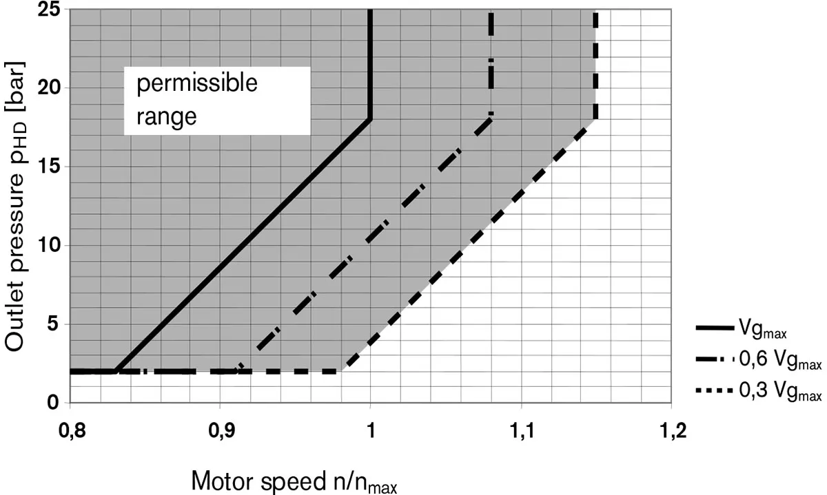
1) Stellen Sie bei maximaler Drehzahl im geschlossenen Kreislauf sicher, dass der Motorausgangsdruck mindestens ≥18 bar beträgt.
2) Im offenen Kreis Δp 280 bar bei PBoostpress. 2 bar
Im geschlossenen Kreis Δp 260bar bei PBoostpress. 20 bar
Erforderlicher Mindestausgangsdruck (Niederdruck) an Anschluss A (B)
je nach Motordrehzahl
Größe berechnen
| Fluss | qv=(Vg∙n)/(1000∙ηv) | [l/min] | Vg= Verdrängung pro Umdrehung in cm³3 Δp = Differenzdruck in bar n=Drehzahl in U/min ηvVolumetrischer Wirkungsgrad ηmhMechanisch-hydraulischer Wirkungsgrad ηt= Gesamtwirkungsgrad (ηt = ηv ∙ηmh) TKDrehmomentkonstante |
| Drehmoment | T=(1,59∙Vg∙ Δp∙ηmh)/100 | [Nm] | |
| oder | T=Tk∙ Δp∙ηmh | ||
| Ausgangsleistung | P=(2π∙T∙n)/60000=(qv∙Δp∙ηt)/600 | [kW] | |
| Ausgabegeschwindigkeit | n=(qv∙1000∙ηv)/Vg | [min-1] | |
Zulässige Radial- und Axialkräfte an der Antriebswelle
| Größe | 28 | 45 | 63 | 85 | ||||
| Max. Radialkraft | |
bei X/2 | FQ-max | N | 1200 | 1500 | 1700 | 2000 |
| Max. Axialkraft | |
FAxt | N | 1000 | 1500 | 2000 | 3000 | |
