Wenzhou Prance Hydraulic Equipment Co., Ltd.

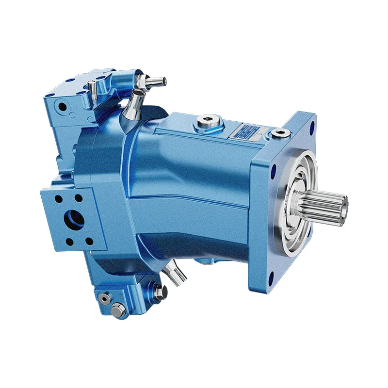
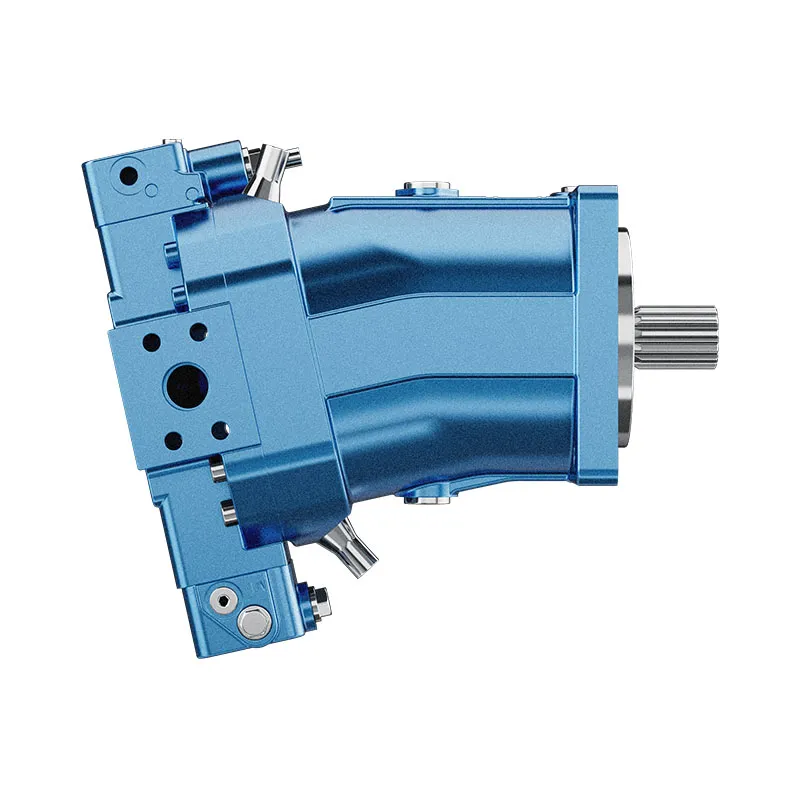

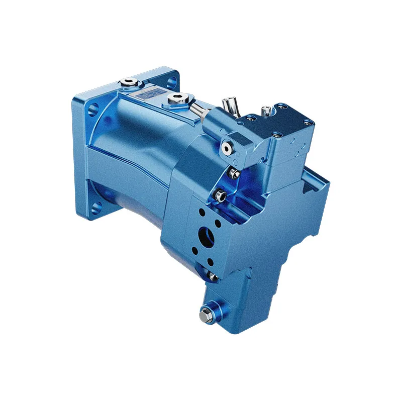
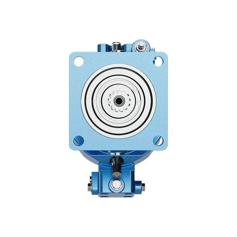
Hydraulic Variable Displacement Piston Motor AA6VM
1.Robust motor with long service life .
2.Approved for very high rotational speeds
3.High control range (can be swiveled to zero)
4.High torque.
5.Variety of contra Is Optionally with flushing and boost-pressure valve mounted
6.Optionally with Integrated or mounted counterbalance valve
7.Bent-axis design
Detaillierte Beschreibung
This hydraulic motor adopts a professional bent-axis design, which optimizes internal structural stress distribution and enhances overall operational stability. The motor features a robust and durable structure, effectively resisting wear and fatigue during long-term continuous operation, delivering a reliable long service life. It is certified to operate stably at extremely high rotational speeds with excellent dynamic performance. The device provides a wide control range, allowing the swashplate to be fully swiveled to zero displacement for precise and flexible speed and flow regulation. It maintains outstanding high-torque output under working conditions, offering strong driving power for heavy-load mechanical equipment. The motor supports diverse control configurations, with optional externally mounted flushing and boost-pressure valves to optimize system heat dissipation and inlet pressure. Additionally, it can be fitted with either integrated or installed counterbalance valves as an optional upgrade, effectively preventing load runaway and improving the safety and stability of the entire hydraulic system.
Auswahl und Preisanfrage
This motor series should be selected from the required torque, speed and duty cycle. Confirm displacement, working pressure, case-drain arrangement where applicable, mounting interface and fluid conditions before final selection.
Angaben für Ihre Angebotsanfrage
- Required torque and speed at working pressure
- Preferred displacement or calculated displacement
- Mounting flange, shaft and port orientation
- Duty cycle, fluid, temperature and operating environment
Verwandte Ressourcen
Code eingeben
| 01 | 02 | 03 | 04 | 05 | 06 | 07 | 08 | 09 | 10 | 11 | 12 | 13 | 14 | 15 | 16 | 17 | 18 | 19 | 20 | |||
| AA6V | M | 250 | / | 63 | W | - | V | S | D | - |
Hydraulic fluid
| 01 | Mineral oil and HFD. HFD only in combination with long-life bearings "L" (without code) | |
| HFB, HFC hydraulic fluid only in conjunction with long-life bearings “L” | E |
Axialkolbeneinheit
| 02 | Bent-axis design, variable, nominal pressure 5100 psi (350 bar), maximum pressure 5800 psi (400 bar) | AA6V |
Drive shaft bearing
| 03 | Standard bearing (without code) | |
| Long-life bearing | L |
Betriebsart
| 04 | Motor (plug-in motor A6VE) | M |
size(NG)
| 05 | Geometric displacement | in cm3/rev | 250 |
| in in3/rev | 15.25 |
Steuergerät
| 06 | Proportional control hydraulic | ΔPst= 145 psi (10 bar) | HD1 |
| ΔPst= 365 psi (25 bar) | HD2 | ||
| ΔPst=510 psi (35 bar) | HD3 | ||
| Proportional control electrical1) | U=12 V DC | EP1 | |
| U=24 V DC | EP2 | ||
| Two-point control hydraulic | HZ | ||
| Two-point control electrical1) | U=12 V DC | EZ1 | |
| U=24 V DC | EZ2 | ||
| Automatic control high-pressure related | with minimum pressure increase Δp ≤ approx. 145 psi (10 bar) | HA1 | |
| with pressure increase Δp= 1450 psi (100 bar) | HA2 | ||
| Automatic control speed related pst/ pHD=3/100 | hydraulic travel direction valve | DA |
Pressure control/override (only for HD, EP)
| 07 | Without pressure control/override | ||
| Pressure control fixed setting | fixed setting | D | |
| hydraulic override, two-point | E2) | ||
| hydraulic remote control, proportional | G | ||
Overrides for the HA1 and HA2 controls
| 08 | Without override | |
| Hydraulic override, remonte control, proportinal | T |
Serie
| 09 | Series 6, index 3 | 63 |
Drehrichtung
| 10 | Viewed on drive shaft, bidirectional | W |
Setting range for displacement3)
| 11 | Vg-Moll = 0 to 0.4 VG-Max VG-Max=VG-Max to 0.8 VG-Max | 1 |
| VG-Max > 0.4 VG-Max to 0.8 VG-Max VG-Max=VG-Max to 0.8 VG-Max | 2 |
•=Available ○=On request -=Not available
1) Hirschmann connector Standard
2) Fitted as standard with version D
3) Please specify exact settings for Vg min und VG-Max in plain text when ordering: Vg min = ... in3 (cm3), Vg Max = ... in3 (cm3)
Dichtungsmaterial
| 12 | FKM (Fluorelastomer) | V |
Antriebswelle
| 13 | Splined shaft ANSI B92.1a | S |
Montageflansch
| 14 | SAE J744 -4-bolt 165-4 | D |
Funktionierender Port4)
| 15 | SAE working ports A and B at rear | 51 | 0 | ● | 510 |
| 7 | ● | 517 | |||
| SAE working ports A and B at side, opposite | 52 | 0 | ● | 520 | |
| 7 | ● | 527 |
Valves: 0=Without valve 7=Flushing and boost-pressure valve, mounted
Speed sensor
| 16 | Without speed sensor (without code) | ||
| Prepared for HDD speed sensor | ▲ | F | |
| HDD speed sensor mounted5) | ▲ | H |
Schwenkwinkelsensor
| 17 | Ohne Schwenkwinkelsensor (ohne Code) | |
| Optical swivel angle sensor | V | |
| Elektrischer Schwenkwinkelsensor | E |
Beginn der Steuerung
| 18 | At Vg-Moll (standard for HA) | A |
| At VG-Max (standard for HD, HZ, EP, EZ, DA) | B |
Standard / special version
| 19 | Standardversion | 0 |
| Special version | -S |
•=Available ○=On request ▲=Not for new projects -=Not available
Notices
▶Note the project planning notes
▶When ordering, please provide the relevant technical data additionally to the type code.
4) Fastening threads, SAE
5)Specify type code separately for sensor in accordance with data sheet 95135 - HDD and observe the requirements for the electronics.
Technische Daten
| Größe | NG | 250 | ||
| Displacement geometric, per revolution1) | VG-Max | in3 | 15.26 | |
| cm3 | 250 | |||
| Vg-Moll | in3 | 0 | ||
| cm3 | 0 | |||
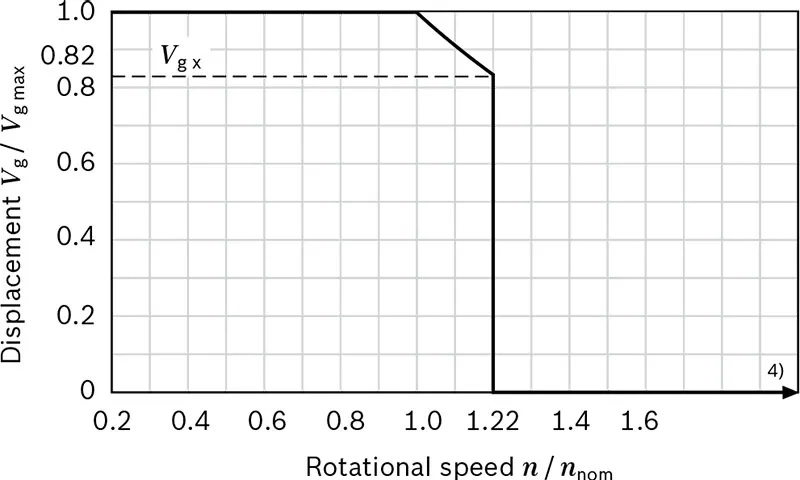
| Vg x | in3 | 12.51 | ||
| cm3 | 205 | |||
| Maximum rotationalspeed2) (while adhering to the maximum permissible inlet flow) | at VG-Max | nnom | U/min | 2700 |
| at Vg<Vgx | nMax | U/min | 3300 | |
| at Vg 0 | nMax | U/min | Please contact us | |
| Inlet flow | at nnom und VG-Max | qv max | gpm | 178 |
| l/min | 675 | |||
| Drehmoment3) | at VG-Max and Δp = 5800 psi(400 bar) | T | lb-ft | - |
| Machs gut | - | |||
| at VG-Max and Δp = 5100 psi(350 bar) | lb-ft | 1026 | ||
| Machs gut | 1391 | |||
| Rotary stiffness | VG-Max to Vg/2 | Cmin | lb-ft/rad | |
| kNm/rad | 60 | |||
| Vg/2 to 0 (interpolated) | Cmin | lb-ft/rad | ||
| kNm/rad | 181 | |||
| Moment of inertia for rotary group | JTW | lb-ft2 | 1.448 | |
| kgm2 | 0.061 | |||
| Maximale Winkelbeschleunigung | α | rad/s2 | 10000 | |
| Fallzahl | V | gal | 0.79 | |
| l | 3.0 | |||
| Weight, approx. | m | lbs | 220 | |
| kg | 100 | |||
Speed range
The minimum rotational speed nmin is not restricted. Please consult us regarding applications requiring uniformity of the rotatory motion at low speeds.
▼Permissible displacement in relation to speed
Notizen
▶Theoretical values, without efficiency and tolerances;values rounded
▶Operation above the maximum values or below the minimum values may result in a loss of function, a reduced service life or in the destruction of the axial piston unit. Other permissible limit values, such as speed variation, reduced angular acceleration as a function of the frequency and the permissible angular acceleration at start (lower than the maximum angular acceleration) can be found in data sheet 90261.
Bestimmung der Betriebskennlinien
| Inlet flow | qv=(Vg×n)/(231×ηv) | [gpm] | ((Vg×n)/(1000×ηv)) | [l/min] |
| Drehzahl | n=(qv×231×ηv)/Vg | [rpm] | ((qv×1000×ηv)/Vg) | [rpm] |
| Drehmoment | T=(Vg×Δp×ηmh)/(24×π) | [lb-ft] | ((Vg×Δp×ηmh)/(20×π)) | [Nm] |
| Macht | P=(2π×T×n)/33000=(qv×Δp×ηt)/1714 | [HP] | ((2π×T×n)/60000=(qv×Δp×ηt)/600) | [kW] |
| Schlüssel Vg=Displacement per revolution [in3 (cm3)] Δp=Differential pressure [psi (bar)] n=Rotational speed [rpm] ηv=Volumetric efficiencyI ηmh=Mechanical-hydraulic efficiency ηt=Total efficiency (nt=ny·nmh) |
||||
1)The minimum and maximum displacement can be steplessly adjusted,see type code . (standard setting if ordering code is missing: Vg min = 0.2 × Vg Max, VG-Max = Vg Max).
2) The values are applicable:
- for the optimum viscosity range from νentscheiden = 170 to 75 SUS (36 to 16 mm2/s)
- with hydraulic fluid based on mineral oils
3)Torque without radial force, with radial force.
4) Values in this range on request
Permissible radial and axial forces of the drive shafts
| Größe | NG | 250 | ||
| Antriebswelle | DIA | in | 2 | |
| Maximum radial force at distance a (from shaft collar) | 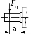 |
FQ-max | lb | 2701) |
| N | 12001) | |||
| a | in | 1.32 | ||
| mm | 33.5 | |||
| Maximum torque at FQ-max | TQ-max | lb-ft | 2) | |
| Machs gut | 2) | |||
| Maximum differential pressure at VG-Max und FQ-max | ΔpQ-max | psi | 2) | |
| bar | 2) | |||
| Maximum axial force at standstill or depressurized operation | 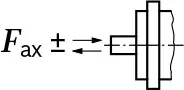 |
+FAch, Max | lb | 0 |
| N | 0 | |||
| -FAch, Max | lb | 270 | ||
| N | 1200 | |||
| Permissible axial force per psi (bar) working pressure | +Fax perm/bar | lb/psi | 2) | |
| N/bar | 2) | |||
Notices
▶The values given are maximum values and do not apply to continuous operation.
▶The permissible axial force in -Fax direction is to be avoided, because thereby the bearing life is reduced.
▶Special requirements apply in the case of belt drives.Please contact us.
Effect of radial force Fq on the service life of bearings
By selecting a suitable direction of radial force Fa, the load on the bearings, caused by the internal rotary group forces can be reduced, thus optimizing the service life of the bearings. Recommended position of mating gear is dependent on direction of rotation. Example:
▼Toothed gear output drive
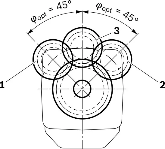
1 Direction of rotation "counter-clockwise", pressure at port B
2 Direction of rotation "clockwise", pressure at port A
3 Bidirectional direction of rotation
1) When at standstill or when axial piston unit working in depressurized conditions. Higher forces are permissible under pressure,please contact us.
2) Please contact us.
