Wenzhou Prance Hydraulic Equipment Co., Ltd.


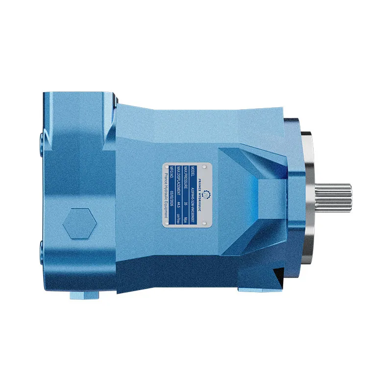
A10FM Fixed Displacement Axial Piston Motor
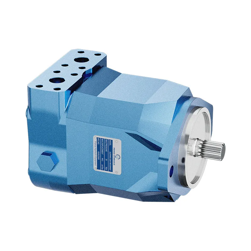
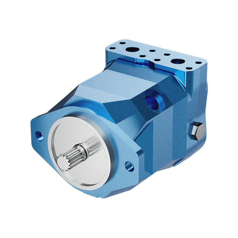
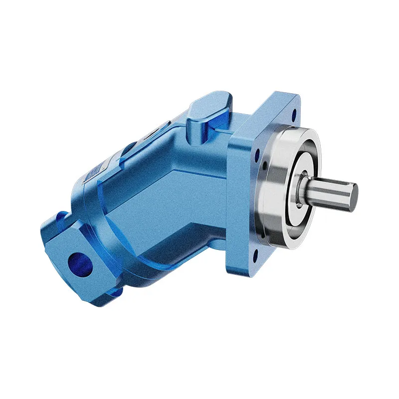
The A10FM is a fixed displacement axial piston motor. It should not be confused with the variable A10VM. The existing product information lists SAE interfaces and an optional anti-cavitation valve arrangement for fan-drive configurations.
- Fixed displacement A10 motor
- SAE mechanical and hydraulic interfaces
- Mobile and industrial applications
- Anti-cavitation valve option requires confirmation
PRANCE HYDRAULIC · PRODUCT SERIES
A10FM Fixed Displacement Axial Piston Motor
Axial piston; swashplate, fixed displacement · Confirm open or closed circuit conditions
The A10FM is a fixed displacement axial piston motor. It should not be confused with the variable A10VM. The existing product information lists SAE interfaces and an optional anti-cavitation valve arrangement for fan-drive configurations.
Model
✓
Request a QuotationTechnische Daten & Datenblatt anzeigenA10FMAxial piston; swashplate, fixed displacement
Confirm the complete model and approved specification with Prance Hydraulic. Product-series references alone do not establish interchangeability.
Configuration review · Technical documentation · Product selection
Produktdetails
- Fixed displacement A10 motor
- SAE mechanical and hydraulic interfaces
- Mobile and industrial applications
- Anti-cavitation valve option requires confirmation
CATEGORIES: Konstantmotor, Kolbenmotor
A10FM Features & Application
Fixed displacement A10 motor
For a fixed displacement, flow and speed remain linked by the selected displacement. Check the actual operating point and efficiency.
SAE mechanical and hydraulic interfaces
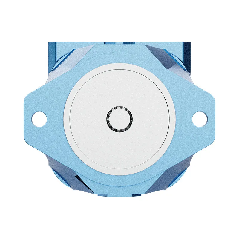
Check pilot diameter, bolt pattern, shaft engagement or port pattern against the approved installation drawing.
Mobile and industrial applications
Check the required shaft torque and speed at the same operating point. Include starting duty, return pressure and external shaft loads.
Anti-cavitation valve option requires confirmation
Specify the full MS order code, installation drawing and operating duty so the quotation can identify the proposed configuration.
A10FM Specifications
| Series / model | A10FM |
|---|---|
| Product type | A10FM Fixed Displacement Axial Piston Motor |
| Design | Axial piston; swashplate, fixed displacement |
| Circuit / selection | Confirm open or closed circuit conditions |
| Hubregelung | Fixed; A10VM is the separate variable-motor family |
| Interface reference | SAE; confirm the selected flange, shaft and ports |
A10FM Selection & Configuration
The A10FM is a fixed displacement axial piston motor. It should not be confused with the variable A10VM. The existing product information lists SAE interfaces and an optional anti-cavitation valve arrangement for fan-drive configurations.
For a fan drive, specify acceleration, deceleration and the possibility of the fan overrunning the oil supply. Confirm replenishment and any anti-cavitation option in the ordered configuration. Electrical control elsewhere in a circuit does not make the A10FM displacement variable.
cURL Too many subrequests by single Worker invocation. To configure this limit, refer to https://developers.cloudflare.com/workers/wrangler/configuration/#limits.
cURL Too many subrequests by single Worker invocation. To configure this limit, refer to https://developers.cloudflare.com/workers/wrangler/configuration/#limits.
Hydraulic pumps · Hydraulic motors · Hydraulic valves
Send the MS nameplate, operating requirements and installation drawing for a configuration review before quoting.
- Model review — send the full model code or an existing nameplate photograph.
- Interface matching — confirm shaft, mounting flange, rotation and ports.
- Operating conditions — provide flow, pressure, speed, fluid and duty cycle.
- Documentation — request the relevant product data and drawings for your review.

A10FM Buying Guide
Use this sequence to prepare the A10FM configuration for review and quotation.
- Define starting and continuous torque, speed range and duty cycle.
- Specify available flow, work-port pressure difference and return pressure.
- Confirm the displacement setting and required behavior during starting and stopping.
- Check shaft, mounting pilot, flange, port orientation and external loads.
- Review case drainage, replenishment and any displacement control.
- Specify fluid conditions and any independent braking requirement.
- Approve the complete model, operating envelope, drawing and quantity.
Selection, Documentation & Project Support

Selection Support
Learn more →Share your hydraulic circuit, operating point and installation requirements for a configuration discussion.
Flow · Pressure · Speed · Interfaces

Technical Resources
Learn more →Review product documentation, model codes and technical data before finalizing the specification.
Datasheets · Model codes · Drawings

Project Inquiries
Learn more →Send your required model, quantity, application and project requirements to discuss your inquiry.
Product inquiries · Configuration review
Configuration, Quantity & Delivery
Confirm the complete MS code, approved drawing and operating limits. Availability, quantity, documentation and delivery date are confirmed in the quotation.
Discuss Your A10FM Application
Send the full model code, operating duty, installation details and quantity.
Request a A10FM QuotationA10FM Questions Before Ordering
What type of product is the A10FM?
A10FM Fixed Displacement Axial Piston Motor. Design: Axial piston; swashplate, fixed displacement. Confirm open or closed circuit conditions. Confirm the complete order code for the offered version.
Can a similar motor replace the A10FM?
cURL Too many subrequests by single Worker invocation. To configure this limit, refer to https://developers.cloudflare.com/workers/wrangler/configuration/#limits.
cURL Too many subrequests by single Worker invocation. To configure this limit, refer to https://developers.cloudflare.com/workers/wrangler/configuration/#limits
cURL Too many subrequests by single Worker invocation. To configure this limit, refer to https://developers.cloudflare.com/workers/wrangler/configuration/#limits.
A10FM Technical Data & Documents
View A10FM catalog data and operating conditions
cURL Too many subrequests by single Worker invocation. To configure this limit, refer to https://developers.cloudflare.com/workers/wrangler/configuration/#limits.
Technische Daten
Flüssigkeiten
Prior to project design, please see our technical data sheets RE 90220 (mineral oil) and RE 90221 (environmentally acceptable fluids) for detailed information on fluids and operating conditions. For operation on environmentally acceptable fluids please consult us (when ordering, please state in clear text the fluid to be used).Betriebsviskositätsbereich
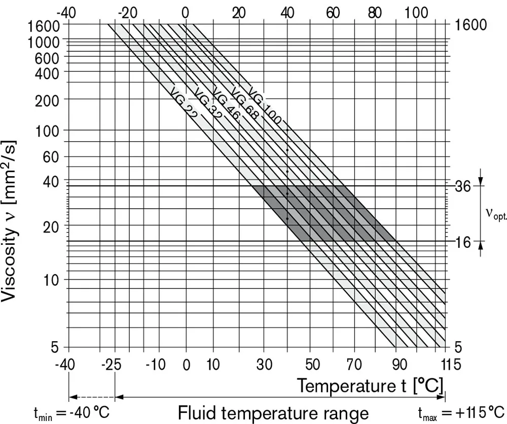
To achieve optimum values for efficiency and service life we recommend an operation viscosity (at operating temperature)within the range, νentscheiden = opt. operating viscosity 16…36 mm2/s referred to the tank temperature (open circuit).Grenze des Viskositätsbereichs
For critical operation conditions the following values apply: νmin.= 5 mm2/s (closed circuit) 10 mm2/s (open circuit) for short periods (t ≤ 1 min) at a max. perm. temperature of 115 ℃. Please note that the max. leakage fluid temperature of 115 ℃ is also not exceeded in certain areas (for instance bearing area).The fluid temperature in the bearing area is approx.5 K higher than the average leakage fluid temperature νMax= 1600 mm2/s for short periods (t≤1 min) on cold start (tmin. p ≤ 30 bar, n ≤ 1000 min⁻¹-1Bei Temperaturen zwischen -40℃ und -25℃ sind besondere Maßnahmen erforderlich; für weitere Informationen kontaktieren Sie uns bitte. Detaillierte Informationen zum Betrieb bei niedrigen Temperaturen finden Sie im Datenblatt RE 90300-03-B.Auswahldiagramm
Hinweise zur Auswahl der Hydraulikflüssigkeit
In order to select the correct fluid, it is necessary to know the operating temperature in the tank (open circuit) in relation to the ambient temperature. The fluid should be selected so that within the operating temperature range, the viscosity lies within the optimum range (νentscheiden),see shaded section of the selection diagram. We recommend to select the higher viscosity grade in each case. Example: at an ambient temperature of X℃ the operating temperature in the tank is 60℃. In the optimum viscosity range(νentscheiden; schraffierter Bereich) dies entspricht den Viskositätsklassen VG 46 bzw. VG 68; VG 68 sollte gewählt werden.Wichtig:
The leakage oil (case drain oil) temperature is influenced by pressure and input speed and is always higher than the tank temperature. However, at no point of the component may the temperature exceed 115℃. If it is not possible to comply with the above conditions because of extreme operating parameters please consult us.Filtration der Hydraulikflüssigkeit
Filtration improves the cleanliness level of the hydraulic fluid,which, in turn, increases the service life of the axial piston unit. To ensure the functional reliability of the axial piston unit, a gravimetric evaluation is necessary for the hydraulic fluid to determine the amount of contamination by solid matter and to determine the cleanliness level according to ISO 4406.A cleanliness level of at least 20/18/15 to ISO 4406 is to be maintained. If above requirements cannot be maintained please consult us.Betriebsdruckbereich
Druck am Arbeitsleitungsanschluss (Druckanschluss) A oder B| Nenndruck Pnom | 280 bar absolut |
| Maximaler Druck PMax | 350 bar absolut |
| Einzelne Betriebsprüfung | 2,5 ms |
| Gesamtbetriebsdauer | 300 Std. |
| Mindestdruck (Hochdruckseite) | 10 bar2) |
| Druckänderungsrate RA max | 16000 bar/s |
Ausgangsdruck
| bei nMax | |
| Mindestdruck auf der Niederdruckseite Pabsolutes Maximum | 18 bar |
Lecköldruck
Maximum permissible case drain pressure (at port L, L1):| Pmax abs Leerlaufbetrieb des Motors | 4 bar ABS |
| Pmax abs Motorbetrieb im geschlossenen Kreis | 4 bar ABS |
| Pmax abs Pumpen-/Motorenbetrieb im offenen Kreis | 2 bar ABS |
Fließrichtung
| auf der Antriebswelle betrachtet | |||||
| im Uhrzeigersinn drehend | gegen den Uhrzeigersinn erfolgende Drehung | ||||
| Von A nach B | B zu A | ||||
Definitionen
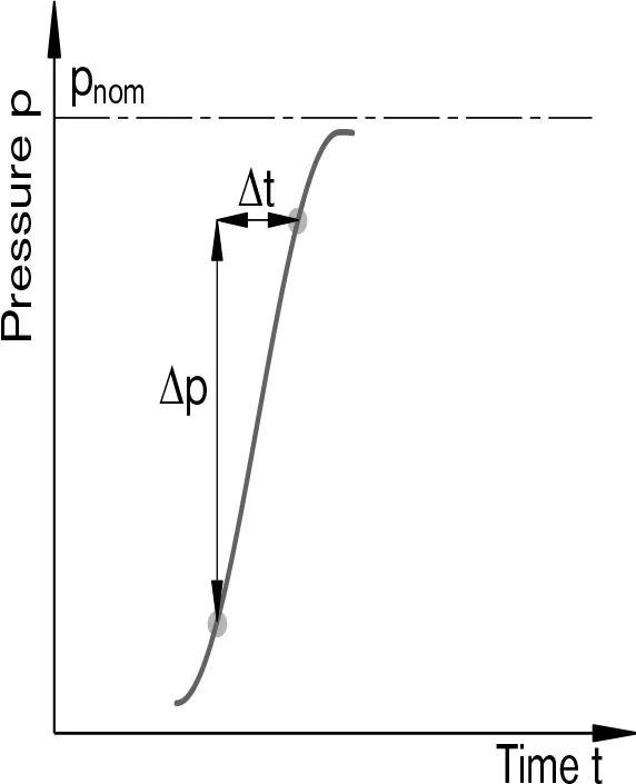
Nenndruck Pnom The nominal pressure corresponds to the maximum design pressure. Maximaler Druck PMax Der Höchstdruck entspricht dem maximalen Betriebsdruck innerhalb des einzelnen Betriebszeitraums. Die Summe der einzelnen Betriebszeiträume darf den Gesamtbetriebszeitraum nicht überschreiten. Mindestdruck (Hochdruckseite) Mindestdruck an der Hochdruckseite (A oder B), der erforderlich ist, um Schäden an der Axialkolbeneinheit zu vermeiden. Druckänderungsrate RA Zulässige Höchstwerte für Druckanstiegs- und Druckabfallgeschwindigkeiten bei einer Druckänderung über den gesamten Druckbereich.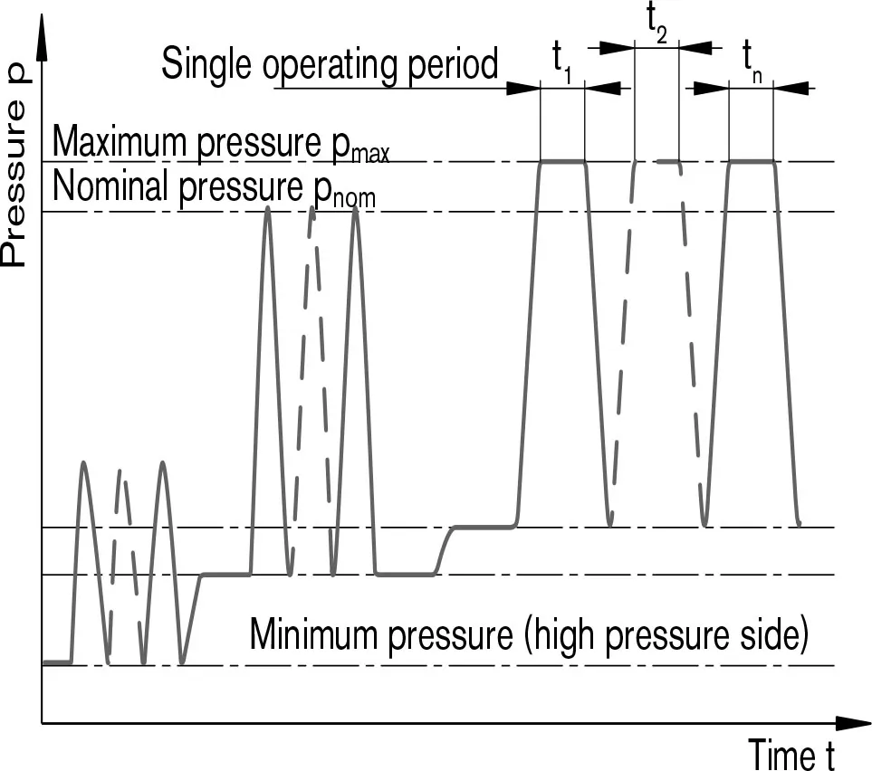 Gesamte Betriebsdauer = t1 + t2 +… + tn
1)Weitere Werte auf Anfrage
2)Niedrigere Drücke zeitabhängig, bitte konsultieren Sie uns.
Wertestabelle (Theoretische Werte, ohne Wirkungsgrad und Toleranzen: Wert gerundet)
| Größe | NG | 010 | 011 | 014 | 016 | 018 | 023 | ||
| Verschiebung | VG-Max | cm3 | 10.6 | 11.5 | 14.1 | 16.1 | 18 | 23.5 | |
| Geschwindigkeit1) | 5000 | 4200 | 4200 | 4200 | 4200 | 4900 | |||
| bei VG-Max | nnom | U/min | |||||||
| Eingangsfluss | 53 | 48 | 59 | 68 | 76 | 115 | |||
| bei nnom | qv max | l/min | |||||||
| Macht | 24.7 | 22.5 | 27.6 | 31.6 | 35.3 | 53.6 | |||
| bei nnom, Δp = 280 bar | P Max | kW | |||||||
| Tatsächliches Anzugsdrehmoment | 37.5 | 30 | 45 | 53 | 67.5 | 75 | |||
| bei n = 0 U/min, Δp = 280 bar | Machs gut | ||||||||
| Drehmoment | 47 | 51 | 63 | 72 | 80 | 105 | |||
| bei VG-Max | Δp = 280 bar | TMax | Machs gut | ||||||
| Torsionssteifigkeit | R | c | Nm/rad | - | - | - | - | 14835 | 28478 |
| Antriebswelle | W | c | Nm/rad | - | - | - | - | - | - |
| C | c | Nm/rad | 15084 | 18662 | 18662 | 18662 | 18662 | 30017 | |
| Trägheitsmoment der Dreheinheit | JTW | kgm2 | 0.0006 | 0.00093 | 0.00093 | 0.00093 | 0.00093 | 0.0017 | |
| Maximale Winkelbeschleunigung | α | rad/s2 | 8000 | 6800 | 6800 | 6800 | 6800 | 5500 | |
| Fallzahl | V | L | 0.1 | 0.15 | 0.15 | 0.15 | 0.15 | 0.6 | |
| Gewicht ca. | m | kg | 5 | 6.5 | 6.5 | 6.5 | 6.5 | 12 | |
| Größe | NG | 028 | 037 | 045 | 058 | 063 | ||
| Verschiebung | VG-Max | cm3 | 28.5 | 11.5 | 14.1 | 16.1 | 18 | |
| Geschwindigkeit1) | ||||||||
| bei VG-Max | nnom | U/min | 4700 | 4200 | 4000 | 3600 | 3400 | |
| Eingangsfluss | 134 | 154 | 178 | 209 | 215 | |||
| bei nnom | qv max | l/min | ||||||
| Macht | 62.5 | 71.8 | 83.1 | 97.4 | 100.1 | |||
| bei nnom, Δp = 280 bar | P Max | kW | ||||||
| Tatsächliches Anzugsdrehmoment | 105 | 125 | 170 | 205 | 230 | |||
| bei n = 0 min-1, Δp = 280 bar | Machs gut | |||||||
| Drehmoment | 127 | 163 | 198 | 258 | 281 | |||
| bei VG-Max | Δp = 280 bar | TMax | Machs gut | |||||
| Torsionssteifigkeit | R | c | Nm/rad | 28478 | 46859 | 46859 | 80590 | 80590 |
| Antriebswelle | W | c | Nm/rad | - | 38489 | 38489 | 60907 | 60907 |
| C | c | Nm/rad | 30017 | 46546 | 46546 | 87667 | 87667 | |
| Trägheitsmoment der Dreheinheit | JTW | kgm2 | 0.0017 | 0.0033 | 0.0033 | 0.0056 | 0.0056 | |
| Maximale Winkelbeschleunigung | α | rad/s2 | 5500 | 4000 | 4000 | 3300 | 3300 | |
| Fallzahl | V | L | 0.6 | 0.7 | 0.7 | 0.8 | 0.8 | |
| Gewicht ca. | m | kg | 12 | 17 | 17 | 22 | 22 | |
Notiz
Der Betrieb oberhalb der Maximalwerte oder unterhalb der Minimalwerte kann zu Funktionsverlust, einer verkürzten Lebensdauer oder zur Zerstörung der Axialkolbeneinheit führen. Wir empfehlen, die Belastungen durch Experimente oder Berechnung/Simulation zu überprüfen und mit den zulässigen Werten zu vergleichen.Zulässige Motordrehzahl in Abhängigkeit vom Auslassdruck
Bestimmung der Motorengröße (NG)
| Eingangsfluss | qv=(Vg∙n)/(1000∙ηv) | [l/min] | Vg= Fördervolumen pro Umdrehung in cm3 Δp=Differential pressure in bar n=speed in rpm ηv=Volumetric efficiency ηmh=Mechanical-hydraulic efficiency ηt= Gesamtwirkungsgrad (ηt = ηv ∙ηmhcURL Too many subrequests by single Worker invocation. To configure this limit, refer to https://developers.cloudflare.com/workers/wrangler/configuration/#limitsKDrehmomentkonstante |
| Drehmoment | T=(1,59∙Vg∙ Δp∙ηmh)/100 | [Nm] | |
| oder | T=Tk∙ Δp∙ηmh | ||
| Macht | P=(2π∙T∙n)/60000=(qv∙Δp∙ηt)/600 | [kW] | |
| Ausgabegeschwindigkeit | n=(qv∙1000∙ηv)/Vg | U/min | |
Zulässige Radial- und Axialkräfte auf die Antriebswelle
| Max. Radialkraft bei X/2 | Antriebswelle R; W | Antriebswelle C | FQ-max | N | 250 | 350 | 350 | 350 | 350 | 1200 |
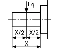 |
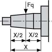 |
|||||||||
| Maximale Axialkraft | 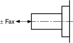 |
± FAch, Max | N | 400 | 700 | 700 | 700 | 700 | 1000 |
| Größe | NG | 28 | 37 | 45 | 58 | 63 | |||
| Max. Radialkraft bei X/2 | Antriebswelle R; W | Antriebswelle C | FQ-max | N | 1200 | 1500 | 1500 | 1700 | 1700 |
|
|
||||||||
| Maximale Axialkraft | |
± FAch, Max | N | 1000 | 1500 | 1500 | 2000 | 2000 | |
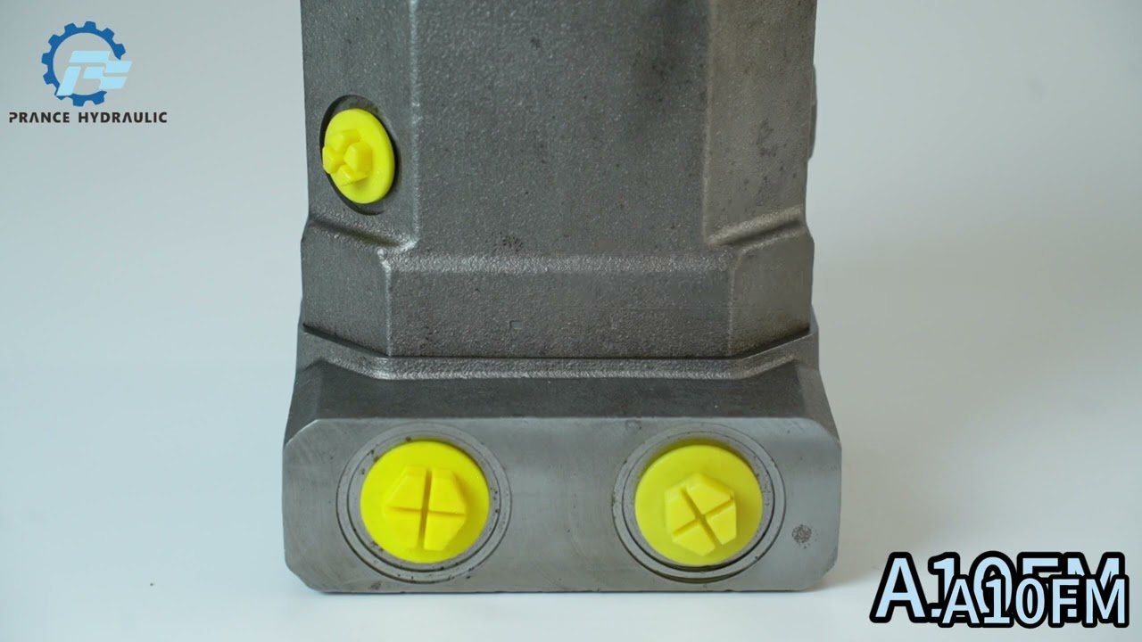
Watch A10FM Product Video
Related Selection Resources
Request a A10FM Quotation
Tell us your required configuration, quantity and application.
Ähnliche Produkte
Compare related hydraulic motors and confirm the complete configuration for your application.


Bestellnummer für Standardprogramm
| A10F | M | / | 52 | - | V | C | ||||||
| 01 | 02 | 03 | 04 | 05 | 06 | 07 | 08 | 09 | 10 | 11 |
Axialkolbeneinheit
| 01 | Schrägscheibenbauweise, konstantes Verdrängungsvolumen, Nenndruck 280 bar, Maximaldruck 350 bar | A10F |
Betriebsart
| 02 | Motor, offener und geschlossener Stromkreis | M |
Größe (NG)
| 03 | Theoretischer Hubraum | 018 | 023 | 028 | 037 | 045 | 058 | 063 |
Serie
| 04 | Serie 5, Index 2 | 52 |
Drehrichtung
| 05 | Auf Antriebswelle betrachtet | im Uhrzeigersinn | R1) |
| gegen den Uhrzeigersinn | L1) | ||
| bidirektional | W |
Robben
| 06 | FKM (Fluorkautschuk) | V |
Antriebswelle
| 018 | 023 | 028 | 037 | 045 | 058 | 063 | |||||
| 07 | Welle mit Passprofil nach ISO 3019-1 (SAE J744) | ○ | ● | ● | ● | ● | ● | ● | R | ||
| Welle mit Passprofil nach ISO 3019-1 (SAE J744) | – | ○ | ○ | ● | ● | ● | ● | W | |||
| Mit Konus, Passfeder und Gewindeende | ○ | ● | ● | ● | ● | ● | ● | C | |||
Montageflansch
| 018 | 023 | 028 | 037 | 045 | 058 | 063 | |||
| 08 | SAE 2-Loch | ○ | ● | ● | ● | ● | ● | ● | C |
Anschlüsse für Versorgungsleitungen
| 018 | 023 | 028 | 037 | 045 | 058 | 063 | |||
| 09 | SAE-Flanschanschlüsse A und B seitlich, gleiche Seite, Befestigungsschrauben metrisch | - | ● | ● | ● | ● | ● | ● | 10N00 |
| Anschlüsse A und B mit Metriscgehendem Gewinde, seitlich, auf derselben Seite | ○ | ● | ● | ● | ● | ● | ● | 16N00 | |
Ventile
| 018 | 023 | 028 | 037 | 045 | 058 | 063 | |||
| 10 | Ohne Ventile | ○ | ● | ● | ● | ● | ● | ● | 0 |
| Mit integriertem Spülventil | - | ● | ● | ● | ● | ● | ● | 7 | |
| Mit integriertem Antikavitationsventil | ○ | ● | ● | ● | ● | ● | ● | 2 | |
Geschwindigkeitssensor
| 018 | 023 | 028 | 037 | 045 | 058 | 063 | |||
| 11 | Ohne Geschwindigkeitssensor | ○ | ● | ● | ● | ● | ● | ● | |
| Vorbereitet für Geschwindigkeitssensor (für induktiven Geschwindigkeitssensor ID) | ○ | ● | ● | ● | ● | ○ | ○ | D | |
• = verfügbar ○ = auf Anfrage — = nicht verfügbar
1) Nur erforderlich in Verbindung mit der Ventilkonfiguration "2" (integriertes Antikavitationsventil)
| A10F | E | / | 52 | - | V | |||||||
| 01 | 02 | 03 | 04 | 05 | 06 | 07 | 08 | 09 | 10 | 11 |
Axialkolbeneinheit
| 01 | Schrägscheibenbauweise, konstantes Verdrängungsvolumen, Nenndruck 280 bar, Maximaldruck 350 bar | A10F |
Betriebsart
| 02 | Motor, offener und geschlossener Stromkreis | E |
Größe (NG)
| 03 | Theoretischer Hubraum | 010 | 011 | 014 | 016 | 018 | 023 | 028 | 037 | 045 | 058 | 063 |
Serie
| 04 | Serie 5, Index 2 | 52 |
Drehrichtung
| 05 | Auf Antriebswelle betrachtet | im Uhrzeigersinn | R1) |
| gegen den Uhrzeigersinn | L1) | ||
| bidirektional | W |
Robben
| 06 | FKM (Fluorkautschuk) | V |
Antriebswelle
| 010 | 011 | 014 | 016 | 018 | 023 | 028 | 037 | 045 | 058 | 063 | |||||
| 07 | Welle mit Passprofil nach ISO 3019-1 (SAE J744) | ○ | ● | ● | ● | ● | ● | ● | ● | ● | ● | ● | R | ||
| Welle mit Passprofil nach ISO 3019-1 (SAE J744) | – | – | – | – | – | ● | ● | ● | ● | ● | ● | W | |||
| Mit Konus, Passfeder und Gewindeende | ● | ● | ● | ● | ● | ● | ● | ● | ● | ● | ● | C | |||
Montageflansch
| 010 | 011 | 014 | 016 | 018 | 023 | 028 | 037 | 045 | 058 | 063 | |||
| 08 | SAE 2-Loch | ● | ● | ● | ● | ● | - | - | - | - | - | - | C2) |
| Spezial 2-Loch | - | - | - | - | - | ● | ● | ● | ● | ● | ● | F | |
| Spezielles 8-Loch | - | ● | ● | ● | ● | - | - | - | - | - | - | H | |
Anschlüsse für Versorgungsleitungen
| 010 | 011 | 014 | 016 | 018 | 023 | 028 | 037 | 045 | 058 | 063 | |||
| 09 | SAE-Flanschanschlüsse A und B, seitlich, gleitende Befestigungsschrauben metrisch | - | - | - | - | - | ● | ● | ● | ● | ● | ● | 10N00 |
| Anschlüsse A und B mit Metriscgehendem Gewinde, seitlich, auf derselben Seite | ● | ● | ● | ● | ● | ● | ● | ● | ● | ● | ● | 16N00 | |
Ventile
| 010 | 011 | 014 | 016 | 018 | 023 | 028 | 037 | 045 | 058 | 063 | |||
| 10 | Ohne Ventile | ○ | ● | ○ | ● | ● | ● | ● | ● | ● | ● | ● | 0 |
| Mit integriertem Spülventil | - | - | - | - | - | ● | ● | ● | ● | ● | ● | 7 | |
| Mit integriertem Antikavitationsventil | ● | ● | ● | ● | ● | ● | ● | ● | ● | ● | ● | 2 | |
Geschwindigkeitssensor
| 010 | 011 | 014 | 016 | 018 | 023 | 028 | 037 | 045 | 058 | 063 | |||
| 11 | Ohne Geschwindigkeitssensor | ● | ● | ● | ● | ● | ● | ● | ● | ● | ● | ● | |
| Vorbereitet für Geschwindigkeitssensor (für induktiven Geschwindigkeitssensor ID) | – | – | – | – | ○ | ● | ● | ● | ● | ○ | ○ | D | |
• = verfügbar ○ = auf Anfrage — = nicht verfügbar
1) Nur in Verbindung mit der Ventilkonfiguration "2" (integriertes Antikavitationsventil) erforderlich
2) R-Welle mit C-Flansch bei Baugrößen 10 bis 18 in Vorbereitung
Technische Daten
Flüssigkeiten
Vor der Projektierung beachten Sie bitte für detaillierte Informationen zu Flüssigkeiten und Betriebsbedingungen unsere technischen Datenblätter RE 90220 (Mineralöl) und RE 90221 (umweltverträgliche Flüssigkeiten).
Für den Betrieb mit umweltverträglichen Medien sprechen Sie uns bitte an (bei der Bestellung bitte das zu verwendende Medium im Klartext angeben).
Betriebsviskositätsbereich
Zur Erzielung optimaler Werte für Wirkungsgrad und Lebensdauer empfehlen wir eine Betriebsviskosität (bei Betriebstemperatur) im Bereich von,
νentscheiden = opt. Betriebsviskosität 16...36 mm2/s
bezogen auf die Tanktemperatur (offener Stromkreis).
Grenze des Viskositätsbereichs
Für kritische Betriebsbedingungen gelten folgende Werte:
νmin.= 5 mm2Ruhekreis
10 mm2/s (offener Stromkreis)
für kurze Zeiträume (t ≤ 1 min)
bei einer max. dauerhaften Temperatur von 115 °C.
Bitte beachten Sie, dass die max. Leckageflüssigkeitstemperatur von 115 ℃ auch in bestimmten Bereichen (z. B. Lagerbereich) nicht überschritten wird. Die Flüssigkeitstemperatur im Lagerbereich ist ca. 5 K höher als die durchschnittliche Leckageflüssigkeitstemperatur
νMax= 1600 mm2/s
für kurze Zeit (t≤1 min)
beim Kaltstart
(tmin. p ≤ 30 bar, n ≤ 1000 min⁻¹-1, -25 °C).
Bei Temperaturen zwischen -40℃ und -25℃ sind besondere Maßnahmen erforderlich; für weitere Informationen kontaktieren Sie uns bitte. Detaillierte Informationen zum Betrieb bei niedrigen Temperaturen finden Sie im Datenblatt RE 90300-03-B.
Auswahldiagramm
Hinweise zur Auswahl der Hydraulikflüssigkeit
Um die richtige Flüssigkeit auszuwählen, ist es erforderlich, die Betriebstemperatur im Tank (offener Kreislauf) im Verhältnis zur Umgebungstemperatur zu kennen.
Das Fluid sollte so ausgewählt werden, dass die Viskosität innerhalb des Betriebstemperaturbereichs im Optimum liegt (νentscheiden), siehe schattierter Bereich im Auswahldiagramm. Wir empfehlen, in jedem Fall die höhere Viskositätsklasse zu wählen.
Beispiel: bei einer Umgebungstemperatur von X℃ beträgt die Betriebstemperatur im Tank 60℃. Im optimalen Viskositätsbereich (νentscheiden; schraffierter Bereich) dies entspricht den Viskositätsklassen VG 46 bzw. VG 68; VG 68 sollte gewählt werden.
Wichtig:
Die Temperatur des Lecköls (Lecköltemperatur) wird durch Druck und Eingangsdrehzahl beeinflusst und ist immer höher als die Tanktemperatur. An keinem Punkt der Komponente darf die Temperatur jedoch 115 °C überschreiten.
Sollte es aufgrund extremer Betriebsparameter nicht möglich sein, die oben genannten Bedingungen einzuhalten, konsultieren Sie uns bitte.
Filtration der Hydraulikflüssigkeit
Die Filtration verbessert den Reinheitsgrad der Hydraulikflüssigkeit, was wiederum die Lebensdauer der Axialkolbeneinheit erhöht.
Zur Gewährleistung der Funktionssicherheit der Axialkolbeneinheit ist eine gravimetrische Auswertung der Hydraulikflüssigkeit erforderlich, um den Feststoffverschmutzungsgrad zu bestimmen und die Reinheitsklasse nach ISO 4406 zu ermitteln. Es ist eine Reinheitsklasse von mindestens 20/18/15 gemäß ISO 4406 einzuhalten.
Wenn die obigen Anforderungen nicht eingehalten werden können, wenden Sie sich bitte an uns.
Betriebsdruckbereich
Druck am Arbeitsleitungsanschluss (Druckanschluss) A oder B
| Nenndruck Pnom | 280 bar absolut |
| Maximaler Druck PMax | 350 bar absolut |
| Einzelne Betriebsprüfung | 2,5 ms |
| Gesamtbetriebsdauer | 300 Std. |
| Mindestdruck (Hochdruckseite) | 10 bar2) |
| Druckänderungsrate RA max | 16000 bar/s |
Ausgangsdruck
| bei nMax | |
| Mindestdruck auf der Niederdruckseite Pabsolutes Maximum | 18 bar |
Lecköldruck
Zulässiger Gehäusedruck
(im Hafen L, L1):
| Pmax abs Leerlaufbetrieb des Motors | 4 bar ABS |
| Pmax abs Motorbetrieb im geschlossenen Kreis | 4 bar ABS |
| Pmax abs Pumpen-/Motorenbetrieb im offenen Kreis | 2 bar ABS |
Fließrichtung
| auf der Antriebswelle betrachtet | |||||
| im Uhrzeigersinn drehend | gegen den Uhrzeigersinn erfolgende Drehung | ||||
| Von A nach B | B zu A | ||||
Definitionen
Nenndruck Pnom
Der Nenndruck entspricht der maximalen Auslegung
Druck.
Maximaler Druck PMax
Der Höchstdruck entspricht dem maximalen Betriebsdruck innerhalb des einzelnen Betriebszeitraums. Die Summe der einzelnen Betriebszeiträume darf den Gesamtbetriebszeitraum nicht überschreiten.
Mindestdruck (Hochdruckseite)
Mindestdruck an der Hochdruckseite (A oder B), der erforderlich ist, um Schäden an der Axialkolbeneinheit zu vermeiden.
Druckänderungsrate RA
Zulässige Höchstwerte für Druckanstiegs- und Druckabfallgeschwindigkeiten bei einer Druckänderung über den gesamten Druckbereich.
Gesamte Betriebsdauer = t1 + t2 +... + tn
1)Weitere Werte auf Anfrage
2)Niedrigere Drücke zeitabhängig, bitte konsultieren Sie uns.
Wertestabelle (Theoretische Werte, ohne Wirkungsgrad und Toleranzen: Wert gerundet)
| Größe | NG | 010 | 011 | 014 | 016 | 018 | 023 | ||
| Verschiebung | VG-Max | cm3 | 10.6 | 11.5 | 14.1 | 16.1 | 18 | 23.5 | |
| Geschwindigkeit1) | 5000 | 4200 | 4200 | 4200 | 4200 | 4900 | |||
| bei VG-Max | nnom | U/min | |||||||
| Eingangsfluss | 53 | 48 | 59 | 68 | 76 | 115 | |||
| bei nnom | qv max | l/min | |||||||
| Macht | 24.7 | 22.5 | 27.6 | 31.6 | 35.3 | 53.6 | |||
| bei nnom, Δp = 280 bar | P Max | kW | |||||||
| Tatsächliches Anzugsdrehmoment | 37.5 | 30 | 45 | 53 | 67.5 | 75 | |||
| bei n = 0 U/min, Δp = 280 bar | Machs gut | ||||||||
| Drehmoment | 47 | 51 | 63 | 72 | 80 | 105 | |||
| bei VG-Max | Δp = 280 bar | TMax | Machs gut | ||||||
| Torsionssteifigkeit | R | c | Nm/rad | - | - | - | - | 14835 | 28478 |
| Antriebswelle | W | c | Nm/rad | - | - | - | - | - | - |
| C | c | Nm/rad | 15084 | 18662 | 18662 | 18662 | 18662 | 30017 | |
| Trägheitsmoment der Dreheinheit | JTW | kgm2 | 0.0006 | 0.00093 | 0.00093 | 0.00093 | 0.00093 | 0.0017 | |
| Maximale Winkelbeschleunigung | α | rad/s2 | 8000 | 6800 | 6800 | 6800 | 6800 | 5500 | |
| Fallzahl | V | L | 0.1 | 0.15 | 0.15 | 0.15 | 0.15 | 0.6 | |
| Gewicht ca. | m | kg | 5 | 6.5 | 6.5 | 6.5 | 6.5 | 12 | |
| Größe | NG | 028 | 037 | 045 | 058 | 063 | ||
| Verschiebung | VG-Max | cm3 | 28.5 | 11.5 | 14.1 | 16.1 | 18 | |
| Geschwindigkeit1) | ||||||||
| bei VG-Max | nnom | U/min | 4700 | 4200 | 4000 | 3600 | 3400 | |
| Eingangsfluss | 134 | 154 | 178 | 209 | 215 | |||
| bei nnom | qv max | l/min | ||||||
| Macht | 62.5 | 71.8 | 83.1 | 97.4 | 100.1 | |||
| bei nnom, Δp = 280 bar | P Max | kW | ||||||
| Tatsächliches Anzugsdrehmoment | 105 | 125 | 170 | 205 | 230 | |||
| bei n = 0 min-1, Δp = 280 bar | Machs gut | |||||||
| Drehmoment | 127 | 163 | 198 | 258 | 281 | |||
| bei VG-Max | Δp = 280 bar | TMax | Machs gut | |||||
| Torsionssteifigkeit | R | c | Nm/rad | 28478 | 46859 | 46859 | 80590 | 80590 |
| Antriebswelle | W | c | Nm/rad | - | 38489 | 38489 | 60907 | 60907 |
| C | c | Nm/rad | 30017 | 46546 | 46546 | 87667 | 87667 | |
| Trägheitsmoment der Dreheinheit | JTW | kgm2 | 0.0017 | 0.0033 | 0.0033 | 0.0056 | 0.0056 | |
| Maximale Winkelbeschleunigung | α | rad/s2 | 5500 | 4000 | 4000 | 3300 | 3300 | |
| Fallzahl | V | L | 0.6 | 0.7 | 0.7 | 0.8 | 0.8 | |
| Gewicht ca. | m | kg | 12 | 17 | 17 | 22 | 22 | |
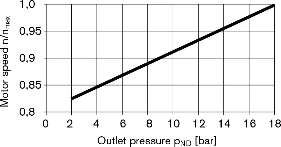
1) Für maximale Geschwindigkeit ist ein Ausgangsdruck (auf der Niederdruckseite) von 18 bar erforderlich.
Notiz
Der Betrieb oberhalb der Maximalwerte oder unterhalb der Minimalwerte kann zu Funktionsverlust, einer verkürzten Lebensdauer oder zur Zerstörung der Axialkolbeneinheit führen. Wir empfehlen, die Belastungen durch Experimente oder Berechnung/Simulation zu überprüfen und mit den zulässigen Werten zu vergleichen.
Zulässige Motordrehzahl in Abhängigkeit vom Auslassdruck
Bestimmung der Motorengröße (NG)
| Eingangsfluss | qv=(Vg∙n)/(1000∙ηv) | [l/min] | Vg= Fördervolumen pro Umdrehung in cm3 Δp = Differenzdruck in bar n=Drehzahl in U/min ηvVolumetrischer Wirkungsgrad ηmhMechanisch-hydraulischer Wirkungsgrad ηt= Gesamtwirkungsgrad (ηt = ηv ∙ηmh) TKDrehmomentkonstante |
| Drehmoment | T=(1,59∙Vg∙ Δp∙ηmh)/100 | [Nm] | |
| oder | T=Tk∙ Δp∙ηmh | ||
| Macht | P=(2π∙T∙n)/60000=(qv∙Δp∙ηt)/600 | [kW] | |
| Ausgabegeschwindigkeit | n=(qv∙1000∙ηv)/Vg | U/min | |
Zulässige Radial- und Axialkräfte auf die Antriebswelle
| Max. Radialkraft bei X/2 | Antriebswelle R; W | Antriebswelle C | FQ-max | N | 250 | 350 | 350 | 350 | 350 | 1200 |
|
|
|||||||||
| Maximale Axialkraft | |
± FAch, Max | N | 400 | 700 | 700 | 700 | 700 | 1000 |
| Größe | NG | 28 | 37 | 45 | 58 | 63 | |||
| Max. Radialkraft bei X/2 | Antriebswelle R; W | Antriebswelle C | FQ-max | N | 1200 | 1500 | 1500 | 1700 | 1700 |
|
|
||||||||
| Maximale Axialkraft | |
± FAch, Max | N | 1000 | 1500 | 1500 | 2000 | 2000 | |
