Wenzhou Prance Hydraulic Equipment Co., Ltd.


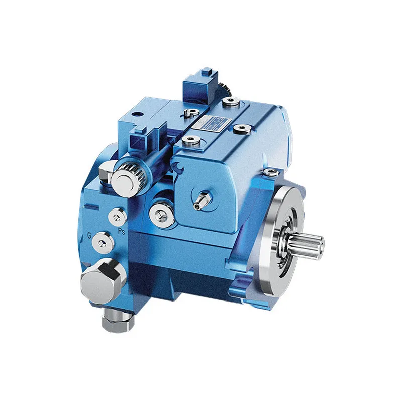
A7VO Bent Axis Variable Displacement Pump
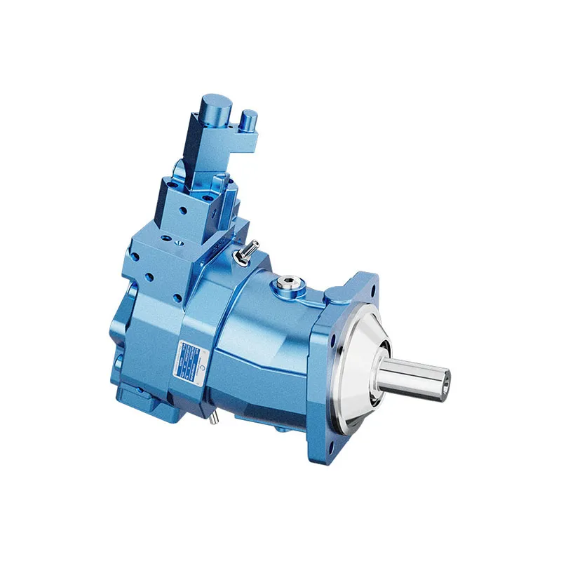
The A7VO variable pump uses a bent-axis rotary group for open-circuit drives. Changing its displacement changes delivered flow at a given drive speed. The selected controller must match the pressure, power or flow behavior required by the machine.
- Variable bent-axis rotary group
- Open-circuit hydrostatic drives
- Mobile and stationary applications
- Control devices selected by order code
PRANCE HYDRAULIC · PRODUCT SERIES
A7VO Bent Axis Variable Displacement Pump
Axial piston; bent axis, variable displacement · Open circuit
The A7VO variable pump uses a bent-axis rotary group for open-circuit drives. Changing its displacement changes delivered flow at a given drive speed. The selected controller must match the pressure, power or flow behavior required by the machine.
Model
✓
Request a QuotationVer Datos Técnicos y Ficha TécnicaA7VOAxial piston; bent axis, variable displacement
Confirm the complete model and approved specification with Prance Hydraulic. Product-series references alone do not establish interchangeability.
Configuration review · Technical documentation · Product selection
Detalles del producto
- Variable bent-axis rotary group
- Open-circuit hydrostatic drives
- Mobile and stationary applications
- Control devices selected by order code
CATEGORIES: Bomba de pistón, Bomba de desplazamiento variable
A7VO Features & Application
Variable bent-axis rotary group
Specify the displacement range or switching arrangement and verify performance at each required setting.
Open-circuit hydrostatic drives
Review normal running, startup and reversal where applicable. The pressure and flow requirements can differ between operating states.
Mobile and stationary applications
Compare the required flow at the actual drive speed and pressure. Check the selected variant rather than combining maxima from different rows.
Control devices selected by order code
Match the complete control option and its command requirements to the existing controller. Similar housings can use different control arrangements.
A7VO Specifications
| Series / model | A7VO |
|---|---|
| Product type | A7VO Bent Axis Variable Displacement Pump |
| Diseño | Axial piston; bent axis, variable displacement |
| Circuit / selection | Open circuit |
| Published nominal sizes | 28, 55, 80, 107 and 160 |
| Listed geometric displacement | 28.1, 54.8, 80, 107 and 160 cm³/rev |
A7VO Selection & Configuration
The A7VO variable pump uses a bent-axis rotary group for open-circuit drives. Changing its displacement changes delivered flow at a given drive speed. The selected controller must match the pressure, power or flow behavior required by the machine.
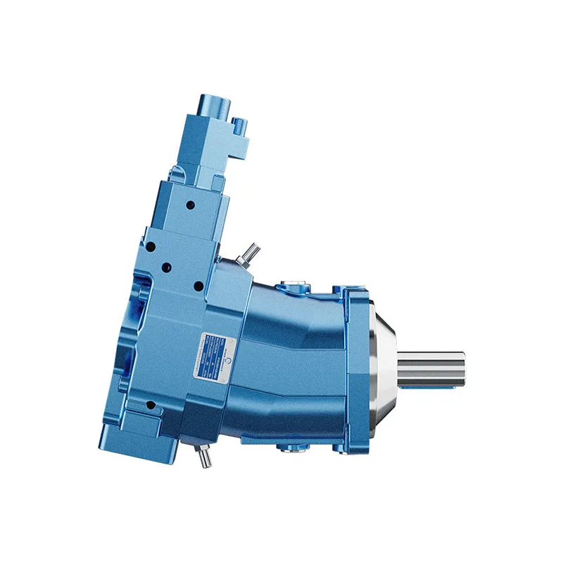
Specify the operating points across the work cycle and compare them with the control characteristic. Verify inlet conditions at the highest flow demand and check the shaft, mounting flange and drain connections against the A7VO drawing.
cURL Too many subrequests by single Worker invocation. To configure this limit, refer to https://developers.cloudflare.com/workers/wrangler/configuration/#limits.
cURL Too many subrequests by single Worker invocation. To configure this limit, refer to https://developers.cloudflare.com/workers/wrangler/configuration/#limits.
Hydraulic pumps · Hydraulic motors · Hydraulic valves
Send the MS nameplate, operating requirements and installation drawing for a configuration review before quoting.
- Model review — send the full model code or an existing nameplate photograph.
- Interface matching — confirm shaft, mounting flange, rotation and ports.
- Operating conditions — provide flow, pressure, speed, fluid and duty cycle.
- Documentation — request the relevant product data and drawings for your review.

A7VO Buying Guide
Use this sequence to prepare the A7VO configuration for review and quotation.
- Define required flow at the actual drive speed and continuous pressure.
- Identify peak pressure, duration and the work cycle.
- Confirm the selected displacement control and any auxiliary-drive requirement.
- Match rotation viewed from the shaft end, shaft, flange and ports.
- Review inlet conditions, drain routing and the installation envelope.
- Confirm fluid, viscosity, temperature, filtration and seals.
- Approve the complete model, control, drawing, quantity and delivery terms.

Selection, Documentation & Project Support

Selection Support
Learn more →Share your hydraulic circuit, operating point and installation requirements for a configuration discussion.
Flow · Pressure · Speed · Interfaces

Technical Resources
Learn more →Review product documentation, model codes and technical data before finalizing the specification.
Datasheets · Model codes · Drawings

Project Inquiries
Learn more →Send your required model, quantity, application and project requirements to discuss your inquiry.
Product inquiries · Configuration review
Configuration, Quantity & Delivery
Confirm the complete MS code, approved drawing and operating limits. Availability, quantity, documentation and delivery date are confirmed in the quotation.
Discuss Your A7VO Application
Send the full model code, operating duty, installation details and quantity.
Request a A7VO QuotationA7VO Questions Before Ordering
What type of product is the A7VO?
A7VO Bent Axis Variable Displacement Pump. Design: Axial piston; bent axis, variable displacement. Open circuit. Confirm the complete order code for the offered version.
Can a similar pump replace the A7VO?
cURL Too many subrequests by single Worker invocation. To configure this limit, refer to https://developers.cloudflare.com/workers/wrangler/configuration/#limits.
cURL Too many subrequests by single Worker invocation. To configure this limit, refer to https://developers.cloudflare.com/workers/wrangler/configuration/#limits
Define required flow at the actual drive speed and continuous pressure. Identify peak pressure, duration and the work cycle. Attach the nameplate, complete order code, installation drawing and required quantity.
A7VO Technical Data & Documents
View A7VO catalog data and operating conditions
cURL Too many subrequests by single Worker invocation. To configure this limit, refer to https://developers.cloudflare.com/workers/wrangler/configuration/#limits.
Datos técnicos
| Tamaño | NG | 28 | 55 | 80 | 107 | 160 | ||
| Desplazamiento geométrico por revolución | Vabuelitax | cm3 | 28.1 | 54.8 | 80 | 107 | 160 | |
| Velocidad de rotación máxima 1) | A VG máximo | nNombre | rpm | 3150 | 2500 | 2240 | 2150 | 1900 |
| A Vg<0.74 x Vg máx | nmax1 | rpm | 4250 | 3400 | 3000 | 2900 | 2560 | |
| Velocidad de rotación máxima 2) | nmax2 | rpm | 4750 | 3750 | 3350 | 3200 | 2850 | |
| Rigidez torsional | Vg máx a V g/2 | cmín | kNm/rad | 5 | 10 | 16 | 21 | 36 |
| Vg/2 a 0 (interpolado) | cmáx | kNm/rad | 16 | 32 | 49 | 67 | 104 | |
| Momento de inercia del grupo rotatorio | JTW | kgm2 | 0.0042 | 0.0042 | 0.0080 | 0.0127 | 0.0253 | |
| Aceleración angular máxima | α | rad/s2 | 35900 | 31600 | 24200 | 19200 | 15300 | |
| Volumen de casos | V | l | 0.5 | 0.75 | 1.2 | 1.5 | 2.4 | |
| Peso (aprox.) | m | kg | 17 | 25 | 40 | 49 | 71 | |
Velocidad máxima permitida (límite de velocidad)

Determinación de las características de funcionamiento
Clave
Vg = Desplazamiento por revolución [cm3] Δp = Differential pressure [bar] n = Rotational speed [rpm] ηv = Volumetric efficiency ηMh = Hydraulic-mechanical efficiency ηt = Eficiencia total (ηt= ηv*ηMh)Notas
▶Theore tical values, without efficiency and tolerances;values rounded ▶Operation above the maximum values or below the minimum values may result in a loss of function, a reduced service life or in the destruction of the axial piston unit. Other permissible limit values, such as speed variation, reduced angular acceleration as a function of the frequency and the permissible angular acceleration at start (lower than the maximum angular acceleration) can be found in data sheet 90261. 1) The values are valid: – At absolute pressure Pabdominales = 1 bar at suction port S – For the optimal viscosity range of velegir = 36 a 16 mm2/s -For hydraulic fluid based on mineral oils. 2) Maximum rotational speed (speed limit) for increased inlet pressure Pabdominales en el puerto de succión S y Vg < Vg máx , ver diagrama.Related Selection Resources
Request a A7VO Quotation
Tell us your required configuration, quantity and application.
Productos relacionados
Compare related hydraulic pumps and confirm the complete configuration for your application.

Código de pedido
| 01 | 02 | 03 | 04 | 05 | 06 | 07 | 08 | 09 | 10 | 11 | 12 | 13 | ||
| A7V | ○ | / | 63 | - | V | B | 01 |
Unidad de pistones axiales
| 01 | Diseño de eje encorvado, variable, presión nominal 350 bar, presión máxima 400 bar | A7V |
Modo de operación
| 02 | Bomba de circuito abierto | ○ |
Tamaño (NG)
| 03 | Desplazamiento geométrico V2 (cm 3), consulte "Datos técnicos" en la página 7 | 28 | 55 | 80 | 107 | 160 |
| Para las tallas 250, 355 y 500, consulte la hoja de datos 92203 | ||||||
Dispositivo de control
| 28 | 55 | 80 | 107 | 160 | |||||
| 04 | Controlador de potencia sin anulación de potencia | ● | ● | ● | ● | ● | LR | ||
| con corte por presión | ● | ● | ● | ● | ● | LRD | |||
| con limitador de carrera | control negativo | Δp = 25 bar | - | ● | ● | ● | ● | LRH1 | |
| con corte de presión y limitador de carrera | control negativo | Δp = 25 bar | - | ● | ● | ● | ● | LRDH1 | |
| con corte por presión y sensor de carga | - | ● | ● | ● | ● | LRDS | |||
| Controlador de potencia con anulación de potencia proporcional hidráulicamente
(solo disponible para giro en sentido horario y con placa de orificios 02) |
|||||||||
| con sensor de carga | - | ● | ● | - | - | LA1S | |||
| con sensor de carga y anulación de LS proporcional hidráulicamente | - | ● | ● | - | - | LA1S5 | |||
| Regulador de presión | ● | ● | ● | ● | ● | Dr. | |||
| controlado a distancia | ● | ● | ● | ● | ● | DRG | |||
| con sensor de carga | - | ● | ● | ● | ● | DRS | |||
| Control hidráulico proporcional | Control positivo | Δp = 10 bar | ● | ● | ● | ● | ● | HD1 | |
| con corte por presión, controlado a distancia | Control positivo | Δp = 10 bar | ● | ● | ● | ● | ● | HD1G | |
| Control eléctrico proporcional | Control positivo | U=24V | ● | ● | ● | ● | ● | EP2 | |
Series
| 05 | Serie 6, índice 3 | 63 |
Sentido de giro
| 28 a 160 | ||||
| 06 | Visto en el árbol de transmisión | en el sentido de las agujas del reloj | ● | R |
| en sentido contrario a las agujas del reloj | ● | L | ||
Material de sellado
| 07 | FKM (fluoroelastómero) | V |
Árbol de transmisión
| 28 a 160 | |||
| 08 | Eje ranurado DIN 5480 | ● | Z |
| Eje con chaveta paralela según la norma DIN 6885 | ● | P | |
Brida de montaje
| 09 | ISO 3019-2; de 4 agujeros | B |
Placa de orificios para líneas de trabajo
| 10 | Puertos de brida SAE A y S en la parte trasera (rosca de fijación métrica) | 01 |
| Orificios de brida SAE A y S en el lateral (disponibles solo para los controladores de potencia LA1S y LA1S5, rosca de fijación métrica) | 02 |
•= disponible -= no disponible  = programa preferido
| 1 | 2 | 3 | 4 | 5 | 6 | 7 | 8 | 9 | 10 | 11 | 12 | 13 | ||
| A7V | ○ | / | 63 | - | V | B | 1 |
Conector para solenoides1)
| 11 | Sin conector (sin solenoide, solo con control hidráulico; sin código) | |
| Conector moldeado DEUTSCH, de 2 pines - sin diodo supresor | P |
Versión estándar / especial
| 12 | Versión estándar (sin código) | |
| Versión especial | -S |
•= disponible -= no disponible = programa preferido
Notas
Preservación:
-Hasta 12 meses de serie
-Hasta 24 meses de larga duración
(indicar en texto plano al realizar el pedido)
Datos técnicos
| Tamaño | NG | 28 | 55 | 80 | 107 | 160 | ||
| Desplazamiento geométrico por revolución | Vabuelitax | cm3 | 28.1 | 54.8 | 80 | 107 | 160 | |
| Velocidad de rotación máxima 1) | A VG máximo | nNombre | rpm | 3150 | 2500 | 2240 | 2150 | 1900 |
| A Vg<0.74 x Vg máx | nmax1 | rpm | 4250 | 3400 | 3000 | 2900 | 2560 | |
| Velocidad de rotación máxima 2) | nmax2 | rpm | 4750 | 3750 | 3350 | 3200 | 2850 | |
| Flujo | A VG máximo y nNombre | qv | l/min | 89 | 137 | 179 | 230 | 304 |
| Poder | A VG máximo , nNombre y Δp = 350 bar | P | kW | 52 | 80 | 105 | 134 | 177 |
| Par de torsión | A VG máximo y Δp = 350 bar | T | Nm | 156 | 305 | 446 | 596 | 891 |
| Rigidez torsional | Vg máx a V g/2 | cmín | kNm/rad | 5 | 10 | 16 | 21 | 36 |
| Vg/2 a 0 (interpolado) | cmáx | kNm/rad | 16 | 32 | 49 | 67 | 104 | |
| Momento de inercia del grupo rotatorio | JTW | kgm2 | 0.0042 | 0.0042 | 0.0080 | 0.0127 | 0.0253 | |
| Aceleración angular máxima | α | rad/s2 | 35900 | 31600 | 24200 | 19200 | 15300 | |
| Volumen de casos | V | l | 0.5 | 0.75 | 1.2 | 1.5 | 2.4 | |
| Peso (aprox.) | m | kg | 17 | 25 | 40 | 49 | 71 | |
Velocidad máxima permitida (límite de velocidad)
Determinación de las características de funcionamiento
| Flujo | qv=(Vg ∙ n ∙ ηv) / 1000 | l/min |
| Par de torsión | T=(Vg ∙ Δp) /(20 ∙ π ∙ ηMh) | Nm |
| Poder | P=(2π ∙ T ∙ n)/60000=(qv ∙ Δp)/(600 ∙ ηt) | kW |
Clave
Vg = Desplazamiento por revolución [cm3]
Δp = Presión diferencial [bar]
n = Velocidad de giro [rpm]
ηv Eficiencia volumétrica
ηMh = Eficiencia hidráulico-mecánica
ηt = Eficiencia total (ηt= ηv*ηMh)
Notas
▶Valores teóricos, sin eficiencia ni tolerancias; valores redondeados
▶El funcionamiento por encima de los valores máximos o por debajo de los valores mínimos puede provocar una pérdida de funcionamiento, una vida útil reducida o la destrucción de la unidad de pistones axiales. Otros valores límite permitidos, como la variación de velocidad, la aceleración angular reducida en función de la frecuencia y la aceleración angular permitida en el arranque (inferior a la aceleración angular máxima), se pueden consultar en la hoja de datos 90261.
1) Los valores son válidos:
- A presión absoluta Pabdominales = 1 bar en el puerto de aspiración S
- Para el rango de viscosidad óptimo de velegir = 36 a 16 mm2/s
-Para fluidos hidráulicos a base de aceites minerales.
2) Velocidad de giro máxima (límite de velocidad) para una presión de entrada P aumentadaabdominales en el puerto de succión S y Vg < Vg máx , ver diagrama.