Wenzhou Prance Hydraulic Equipment Co., Ltd.


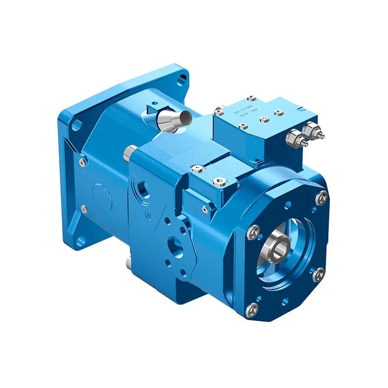
A11VO Open Circuit Variable Piston Pump
The A11VO variable pump is offered for open-circuit mobile hydraulics. Its family documentation includes A11VO and charged A11VLO arrangements, so speed and inlet conditions must be attached to the actual version rather than combined into one family maximum.
- Mobile-application focus
- Self-priming or charged arrangements
- Through-drive configuration available
- Variable displacement and multiple controls
PRANCE HYDRAULIC · PRODUCT SERIES
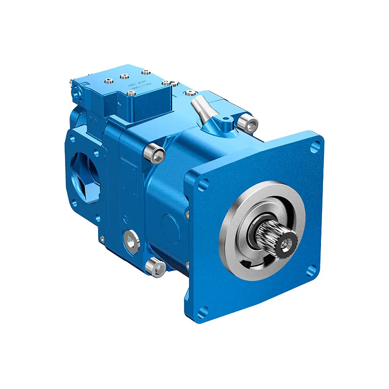
A11VO Open Circuit Variable Piston Pump
Axial piston; variable swashplate · Open circuit
The A11VO variable pump is offered for open-circuit mobile hydraulics. Its family documentation includes A11VO and charged A11VLO arrangements, so speed and inlet conditions must be attached to the actual version rather than combined into one family maximum.
Model
✓
Request a QuotationVer Datos Técnicos y Ficha TécnicaA11VOAxial piston; variable swashplate
Confirm the complete model and approved specification with Prance Hydraulic. Product-series references alone do not establish interchangeability.
Configuration review · Technical documentation · Product selection
Detalles del producto
- Mobile-application focus
- Self-priming or charged arrangements
- Through-drive configuration available
- Variable displacement and multiple controls
CATEGORIES: Bomba de pistón, Bomba de desplazamiento variable
A11VO Features & Application
Mobile-application focus
Specify the full MS order code, installation drawing and operating duty so the quotation can identify the proposed configuration.
Self-priming or charged arrangements
Specify the full MS order code, installation drawing and operating duty so the quotation can identify the proposed configuration.
Through-drive configuration available
Review combined drive torque and simultaneous demand, including any additional pump connected to the drive.
Variable displacement and multiple controls
Match the complete control option and its command requirements to the existing controller. Similar housings can use different control arrangements.
A11VO Specifications
| Series / model | A11VO |
|---|---|
| Product type | A11VO Open Circuit Variable Piston Pump |
| Diseño | Axial piston; variable swashplate |
| Circuit / selection | Open circuit |
| Published family sizes | 40, 60, 75, 95, 130, 145, 190 and 260; version-dependent |
| Inlet arrangement | Confirm self-priming, pressurized tank or charged version |
A11VO Selection & Configuration
The A11VO variable pump is offered for open-circuit mobile hydraulics. Its family documentation includes A11VO and charged A11VLO arrangements, so speed and inlet conditions must be attached to the actual version rather than combined into one family maximum.
Review the required flow and power over the machine work cycle, including any pump mounted on the through drive. Specify the inlet arrangement, control and simultaneous auxiliary demand. Confirm whether the quoted unit is A11VO or A11VLO before applying a speed limit.
cURL Too many subrequests by single Worker invocation. To configure this limit, refer to https://developers.cloudflare.com/workers/wrangler/configuration/#limits.
cURL Too many subrequests by single Worker invocation. To configure this limit, refer to https://developers.cloudflare.com/workers/wrangler/configuration/#limits.
Hydraulic pumps · Hydraulic motors · Hydraulic valves
Send the MS nameplate, operating requirements and installation drawing for a configuration review before quoting.
- Model review — send the full model code or an existing nameplate photograph.
- Interface matching — confirm shaft, mounting flange, rotation and ports.
- Operating conditions — provide flow, pressure, speed, fluid and duty cycle.
- Documentation — request the relevant product data and drawings for your review.

A11VO Buying Guide
Use this sequence to prepare the A11VO configuration for review and quotation.
- Define required flow at the actual drive speed and continuous pressure.
- Identify peak pressure, duration and the work cycle.
- Confirm the selected displacement control and any auxiliary-drive requirement.
- Match rotation viewed from the shaft end, shaft, flange and ports.
- Review inlet conditions, drain routing and the installation envelope.
- Confirm fluid, viscosity, temperature, filtration and seals.
- Approve the complete model, control, drawing, quantity and delivery terms.
Selection, Documentation & Project Support

Selection Support
Learn more →Share your hydraulic circuit, operating point and installation requirements for a configuration discussion.
Flow · Pressure · Speed · Interfaces

Technical Resources
Learn more →Review product documentation, model codes and technical data before finalizing the specification.
Datasheets · Model codes · Drawings

Project Inquiries
Learn more →Send your required model, quantity, application and project requirements to discuss your inquiry.
Product inquiries · Configuration review
Configuration, Quantity & Delivery
Confirm the complete MS code, approved drawing and operating limits. Availability, quantity, documentation and delivery date are confirmed in the quotation.
Discuss Your A11VO Application
Send the full model code, operating duty, installation details and quantity.
Request a A11VO QuotationA11VO Questions Before Ordering
What type of product is the A11VO?
A11VO Open Circuit Variable Piston Pump. Design: Axial piston; variable swashplate. Open circuit. Confirm the complete order code for the offered version.
Can a similar pump replace the A11VO?
cURL Too many subrequests by single Worker invocation. To configure this limit, refer to https://developers.cloudflare.com/workers/wrangler/configuration/#limits.
cURL Too many subrequests by single Worker invocation. To configure this limit, refer to https://developers.cloudflare.com/workers/wrangler/configuration/#limits
Define required flow at the actual drive speed and continuous pressure. Identify peak pressure, duration and the work cycle. Attach the nameplate, complete order code, installation drawing and required quantity.
A11VO Technical Data & Documents
View A11VO catalog data and operating conditions
cURL Too many subrequests by single Worker invocation. To configure this limit, refer to https://developers.cloudflare.com/workers/wrangler/configuration/#limits.
Datos técnicos
Tabla de valores (valores teóricos, sin eficiencia ni tolerancias; valores redondeados)
| Tamaño | A11VO | 40 | 60 | 75 | 95 | 130 | 190 | 190 | 260 | |
| Desplazamiento | Vg máx | cm3 | 42 | 58.5 | 74 | 93.5 | 130 | 190 | 190 | 260 |
| Vg mín | cm3 | 0 | 0 | 0 | 0 | 0 | 0 | 0 | 0 | |
| Velocidad | ||||||||||
| máximo en Vg máx1) máximo en Vg ≤ Vg máx1) | nmáx | rpm | 3000 | 2700 | 2550 | 2350 | 2100 | 2200 | 2100 | 1800 |
| nmax1 | rpm | 3500 | 3250 | 3000 | 2780 | 2500 | 2500 | 2100 | 2300 | |
| Rigidez torsional | Eje Z | Nm/rad | 88894 | 102440 | 145836 | 199601 | 302495 | 302495 | 346190 | 686465 |
| Eje P | Nm/rad | 87467 | 107888 | 143104 | 196435 | 312403 | 312403 | 383292 | 653835 | |
| Eje en S | Nm/rad | 58347 | 86308 | 101921 | 173704 | 236861 | 236861 | 259773 | 352009 | |
| Eje en T | Nm/rad | 74476 | 102440 | 12560 | – | – | – | 301928 | 567115 | |
| Momento de inercia para el grupo rotativo | JTW | Kgm2 | 0.0048 | 0.0082 | 0.0115 | 0.0173 | 0.0318 | 0.0341 | 0.055 | 0.0878 |
| Aceleración angular máxima4) | α | rad/s2 | 22000 | 17500 | 15000 | 13000 | 10500 | 9000 | 6800 | 4800 |
| Capacidad de llenado | V | I | 1.1 | 1.35 | 1.85 | 2.1 | 2.9 | 2.9 | 3.8 | 4.6 |
| Masa (aprox.) | m | kg | 32 | 40 | 45 | 53 | 66 | 76 | 95 | 125 |
| Tamaño | A11VO | 130 | 145 | 190 | 260 | |
| Desplazamiento | Vg máx | cm3 | 130 | 145 | 193 | 260 |
| Vg mín | cm3 | 0 | 0 | 0 | 0 | |
| Velocidad | ||||||
| máximo en Vg máx1) máximo en Vg ≤ Vg máx1) | nmáx | rpm | 2500 | 2500 | 2500 | 2300 |
| nmax1 | rpm | 2500 | 2500 | 2500 | 2300 | |
| Rigidez torsional | Eje Z | Nm/rad | 302495 | 302495 | 346190 | 686465 |
| Eje P | Nm/rad | 312403 | 312403 | 383292 | 653835 | |
| Eje en S | Nm/rad | 236861 | 236861 | 259773 | 352009 | |
| Eje en T | Nm/rad | – | – | 301928 | 567115 | |
| Momento de inercia para el grupo rotativo | JTW | Kgm2 | 0.0337 | 0.036 | 0.0577 | 0.0895 |
| Aceleración angular máxima4) | α | rad/s2 | 10500 | 9000 | 6800 | 4800 |
| Capacidad de llenado | V | I | 2.9 | 2.9 | 3.8 | 4.6 |
| Masa (aprox.) | m | kg | 72 | 73 | 104 | 138 |
Carga radial y axial admisible en el eje de transmisión
Los valores indicados son datos máximos y no admisibles para operación continua| Tamaño | 40 | 60 | 75 | 95 | 130 | 190 | 190 | 260 | ||
| Fuerza radial, máx. a una distancia a, b, c (desde el collar del eje) | Fcuántos máximos a | N mm | 3600 | 5000 | 6300 | 8000 | 11000 | 11000 | 16925 | 22000 |
| 17.5 | 17.5 | 20 | 20 | 22.5 | 22.5 | 26 | 29 | |||
| Fcuántos máximos b | N mm | 2891 | 4046 | 4950 | 6334 | 8594 | 8594 | 13225 | 16809 | |
| 30 | 30 | 35 | 35 | 40 | 40 | 46 | 50 | |||
| Fcuántos máximos c | N mm | 2416 | 3398 | 4077 | 5242 | 7051 | 7051 | 108500 | 13600 | |
| 42.5 | 42.5 | 50 | 50 | 57.5 | 57.5 | 66 | 71 | |||
| Fuerza axial, máx. | ±Fax máx | N | 1500 | 2200 | 2750 | 3500 | 4800 | 4800 | 6000 | 4150 |
Pares de entrada y de transmisión admisibles
| Tamaño | 40 | 60 | 75 | 95 | 130 | 190 | 190 | 260 | ||
| Par de entrada, máx.2) at shaft end P Shaft key DN 6885 | ||||||||||
| TPermanente. | Nm | 468 | 648 | 824 | 1044 | 1448 | 1448 | 2226 | 2787 | |
| Ø32 | Ø35 | Ø40 | Φ45 | Ø50 | Ø50 | Ø 55 | Ø60 | |||
| at Z shaft end DIN 5480 | TPermanente. | Nm | 912 | 912 | 1460 | 2190 | 3140 | 3140 | 3140 | 5780 |
| W35 | W35 | W40 | W45 | W50 | W50 | W50 | W60 | |||
| at S shaft end ANSI B92.1a-1976 (SAE J744) | TPermanente. | Nm | 314 | 602 | 602 | 1640 | 1640 | 1640 | 1640 | 1640 |
| 1 pulgada | 1 1/4 pulg. | 1 1/4 pulg. | 1 3/4 pulgadas | 1 3/4 pulgadas | 1 3/4 pulgadas | 1 3/4 pulgadas | 1 3/4 pulgadas | |||
| at T shaft end ANSI B92.1a-1976 (SAE J744) | TPermanente. | Nm | 602 | 970 | 970 | – | – | – | 2670 | 4070 |
| 1 1/4 pulg | 1 3/8 pulg | 1 3/8 pulg | – | – | – | 2 pulgadas | 2 1/4 pulg | |||
| A través del par motor, máx.3) | TPermanente D. | Nm | 314 | 521 | 660 | 822 | 1110 | 1110 | 1760 | 2065 |
Distribución de par
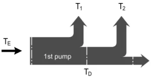
Determinación del valor nominal
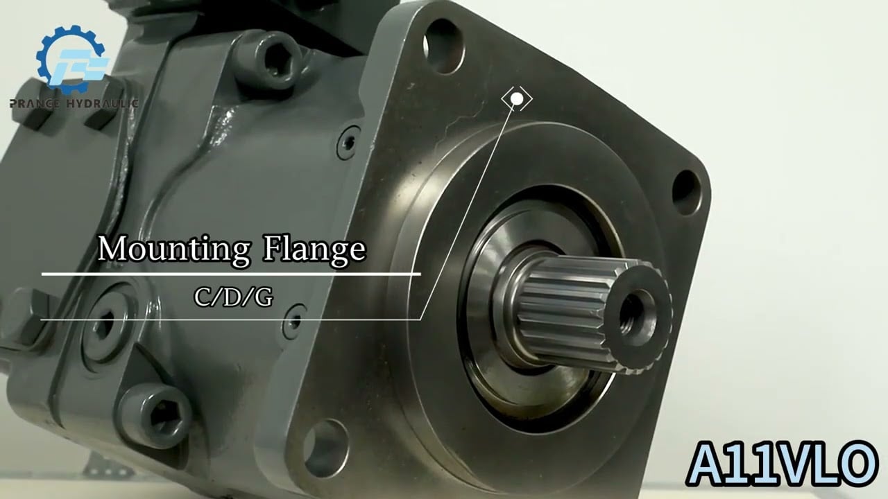
Watch A11VO Product Video
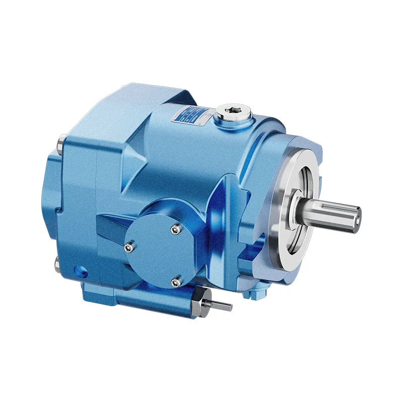
Related Selection Resources
Request a A11VO Quotation
Tell us your required configuration, quantity and application.
Productos relacionados
Compare related hydraulic pumps and confirm the complete configuration for your application.


Código de pedido / Programa estándar
| A11V | ○ | / | 1 | - | N | ||||||||||||
| 01 | 02 | 03 | 04 | 05 | 06 | 07 | 08 | 09 | 10 | 11 | 12 | 13 | 14 | 15 | 16 |
Unidad de pistones axiales
| 01 | Diseño de plato oscilante, variable, presión nominal 350 bar, presión máxima 400 bar | A11V |
Bomba de carga (impulsor)
| 02 | sin bomba de carga | ● | ● | ● | ● | ● | ● | ● | ● | |
| con bomba de carga | - | - | - | - | ● | ● | ● | ● | L |
Operación
| 03 | Bomba de circuito abierto | ○ |
Tamaño
| 04 | ≈Desplazamiento Yg máxen cm3 | 40 | 60 | 75 | 95 | 130 | 145 | 190 | 260 |
Unidad de control
| 05 | Control de energía | LR | ● | ● | ● | ● | ● | ● | ● | ● | LR | |||||||
| con anulación | detección cruzada | negativo | LR | C | ● | ● | ● | ● | ● | ● | ● | ● | LP.C | |||||
| relacionado con la alta presión | negativo | LR3 | ● | ● | ● | ● | ● | ● | ● | ● | LR3 | |||||||
| relacionado con la presión de pilotaje | negativo | LG1 | ● | ● | ● | ● | ● | ● | ● | ● | LG1 | |||||||
| positivo | LG2 | ● | ● | ● | ● | ● | ● | ● | ● | LG2 | ||||||||
| eléctrico | U=12V | negativo | LE1 | ○ | ○ | ○ | ● | ● | ● | ● | ● | LE1 | ||||||
| U=24V | negativo | LE2 | ○ | ● | ● | ● | ● | ● | ● | ● | LE2 | |||||||
| con corte por presión | D | ● | ● | ● | ● | ● | ● | ● | ● | L.D. | ||||||||
| hidráulico, de 2 etapas | E | ● | ● | ● | ● | ● | ● | ● | ● | L.E. | ||||||||
| hidráulico, controlado a distancia | G | ● | ● | ● | ● | ● | ● | ● | ● | L..G. | ||||||||
| con sensor de carga | S | ● | ● | ● | ● | ● | ● | ● | ● | L...S | ||||||||
| eléctrico, anulación por hélice, 24 V | S2 | ○ | ○ | ○ | ● | ● | ● | ● | ● | L...S2 | ||||||||
| anulación hidráulica del puntal | S5 | ○ | ○ | ○ | ● | ● | ● | ● | ● | L...S5 | ||||||||
| con limitador de carrera | negativo
característica |
Δp = 25 bar | H1 | ● | ● | ● | ● | ● | ● | ● | ● | L...H1 | ||||||
| Δp = 10 bar | H5 | ● | ● | ● | ● | ● | ● | ● | ● | L...H5 | ||||||||
| positivo
característica |
Δp = 25 bar | H2 | ● | ● | ● | ● | ● | ● | ● | ● | L...H2 | |||||||
| Δp = 10 bar | H6 | ● | ● | ● | ● | ● | ● | ● | ● | L...H6 | ||||||||
| U=12V | U1 | ● | ● | ● | ● | ● | ● | ● | ● | L...U1 | ||||||||
| U=24V | U2 | ● | ● | ● | ● | ● | ● | ● | ● | L...U2 | ||||||||
| Control de presión | Dr. | ● | ● | ● | ● | ● | ● | ● | ● | Dr. | ||||||||
| con sensor de carga | DRS | ● | ● | ● | ● | ● | ● | ● | ● | DRS | ||||||||
| controlado por remoto | DRG | ● | ● | ● | ● | ● | ● | ● | ● | DRG | ||||||||
| para operación en paralelo | DRL | ● | ● | ● | ● | ● | ● | ● | ● | DRL | ||||||||
| Control hidráulico, relacionado con la presión piloto | característica positiva | Δp = 10 bar | HD1 | ● | ● | ● | ● | ● | ● | ● | ● | HD1 | ||||||
| Δp=25 bar | HD2 | ● | ● | ● | ● | ● | ● | ● | ● | HD2 | ||||||||
| con corte por presión | D | ● | ● | ● | ● | ● | ● | ● | ● | HD.D | ||||||||
| con interruptor de presión, controlado a distancia | G | ○ | ● | ○ | ○ | ○ | ○ | ● | ● | HD.G | ||||||||
| Control eléctrico con solenoide proporcional | característica positiva | U=12V EP1 | ● | ● | ● | ● | ● | ● | ● | ● | EP1 | |||||||
| U=24V EP2 | ● | ● | ● | ● | ● | ● | ● | ● | EP2 | |||||||||
| con corte por presión | D | ● | ● | ● | ● | ● | ● | ● | ● | EP.D | ||||||||
| con corte por presión, control remoto | G | ● | ● | ● | ● | ● | ● | ● | ● | EP.G | ||||||||
En caso de mandos con varias funciones adicionales, observe el orden de las columnas, solo es posible una opción por columna (p. ej. LRDCH2). Las siguientes combinaciones no están disponibles para el regulador de potencia: LRDS2, LRDS5, L.. GS, L.. GS2, L. GS5EC y la combinación L..DG en combinación con los limitadores de carrera H1, H2, H5, H6, U1 y U2.
Series
| 06 | 1 |
Índice
| 07 | Talla 40 ... 130 | 0 |
| Talla 145...260 | 1 |
Sentido de giro
| 08 | Visto desde el extremo del eje | en el sentido de las agujas del reloj | R |
| en sentido contrario a las agujas del reloj | L |
Focas
| 09 | NBR (caucho de nitrilo), anillo de sello de eje en FKM (caucho fluorado) | N |
Extremo del eje
| 10 | 40 | 60 | 75 | 95 | 130 | 145 | 190 | 260 | |||
| Eje estriado DIN 5480 para bomba simple y combinada | ● | ● | ● | ● | ● | ● | ● | ● | Z | ||
| Eje con chaveta paralela DIN 6885 | ● | ● | ● | ● | ● | ● | ● | ● | P | ||
| Eje ranurado ANSI B92.1a-1976 | para bomba única | ● | ● | ● | ● | ● | ● | ● | ● | S | |
| para bomba de combinación | ● | ● | ● | _1) | _1) | _1) | ● | ● | T | ||
Brida de montaje
| 11 | 40 | 60 | 75 | 95 | 130 | 145 | 190 | 260 | ||
| SAE J744 de 2 agujeros | ● | ● | - | - | - | - | - | - | C | |
| SAE J744 de 4 agujeros | - | - | ● | ● | ● | ● | ● | ● | D | |
| SAE J6172) (SAE 3) | - | - | - | ● | ● | ● | ● | - | G |
Puertos de las líneas de servicio
| 12 | Puerto de presión y succión SAE, en el lateral, en el lado opuesto
(con roscas de fijación métricas) |
40 | 60 | 75 | 95 | 130 | 145 | 190 | 260 | |
| ● | ● | ● | ● | ● | ● | ● | ● | 12 |
A través de la unidad
| 40 | 60 | 75 | 95 | 130 | 145 | 190 | 260 | |||||||
| 13 | Brida SAE J7443) | Acoplamiento para eje estriado | ||||||||||||
| - | - | ● | ● | ● | ● | ● | ● | ● | ● | N00 | ||||
| 82-2 | (A) | 5/8 pulgada | 9T 16/32DP | (A) | ● | ● | ● | ● | ● | ● | ● | ● | K01 | |
| 3/4 de pulgada | 11T 16/32DP | (A-B) | ○ | ● | ○ | ● | ● | ● | ○ | ○ | K52 | |||
| 101-2 | (B) | 7/8 de pulgada | 13T 16/32DP | (B) | ● | ● | ● | ● | ● | ● | ● | ● | K02 | |
| 1 pulgada | 15T 16/32DP | (B-B) | ● | ● | ● | ● | ● | ● | ● | ● | K04 | |||
| W35 | 2x30x16x9g | ● | ● | ● | ● | ● | ● | ● | ● | K79 | ||||
| 127-2 | (C)4) | 1 1/4 pulg. | 14T 12/24DP | (C) | - | ● | ● | ● | ● | ● | ● | ● | K07 | |
| 1 1/2 pulg | 17T 12/24DP | (C-C) | - | - | - | ● | ● | ● | ● | ● | K24 | |||
| W30 | 2x30x14x9g | - | ● | ● | ● | ● | ● | ● | ● | K80 | ||||
| W35 | 2x30x16x9g | - | ● | ● | ● | ● | ● | ● | ● | K61 | ||||
| 152-4 | (D) | 1 1/4 pulg. | 14T 12/24DP | (C) | - | - | ● | ● | ● | ● | ● | ● | K86 | |
| 1 3/4 pulg. | 13T 8/16DP | (D) | - | - | - | - | ● | ● | ● | ● | K17 | |||
| W40 | 2x30x18x9g | - | - | ● | ● | ● | ● | ● | ● | K81 | ||||
| W45 | 2x30x21x9g | - | - | - | ● | ● | ● | ● | ● | K82 | ||||
| W50 | 2x30x24x9g | - | - | - | - | ● | ● | ● | ● | K83 | ||||
| 165-4 | (E) | 1 3/4 pulg. | 13T 8/16DP | (D) | - | - | - | - | - | - | ● | ● | K72 | |
| W50 | 2x30x24x9g | - | - | - | - | - | - | ● | ● | K84 | ||||
| W60 | 2x30x28x9g | - | - | - | - | - | - | - | ● | K67 | ||||
Indicador del ángulo de giro
| 14 | 40 | 60 | 75 | 95 | 130 | 145 | 190 | 260 | ||
| sin indicador de ángulo de giro (sin símbolo) | ● | ● | ● | ● | ● | ● | ● | ● | ||
| con indicador óptico del ángulo de giro | ● | - | ● | ● | ● | ● | ● | ● | v | |
| con sensor de ángulo de giro eléctrico | ● | - | ● | ● | ● | ● | ● | ● | R |
Conector para solenoides
| 15 | 40 | 60 | 75 | 95 | 130 | 145 | 190 | 260 | ||
| Conector DEUTSCH moldeado, de 2 pines - sin diodo supresor | ● | ● | ● | ● | ● | ● | ● | ● | P |
Versión estándar/especial
| 16 | Versión estándar | sin símbolo | |
| en combinación con una pieza de acoplamiento o una bomba de acoplamiento | -K | ||
| Versión especial | -S | ||
| en combinación con una pieza de acoplamiento o una bomba de acoplamiento | -SK |
1) ¡Eje en S adecuado para bomba combinada!
2) Para encajar en la carcasa del volante del motor de combustión
3) De 22 agujeros; de 44 agujeros
4) Tamaños 190 y 260 con brida de 2 + 4 agujeros
•= disponible ○= bajo petición -= no disponible  = programa preferido
Datos técnicos
Tabla de valores (valores teóricos, sin eficiencia ni tolerancias; valores redondeados)
| Tamaño | A11VO | 40 | 60 | 75 | 95 | 130 | 190 | 190 | 260 | |
| Desplazamiento | Vg máx | cm3 | 42 | 58.5 | 74 | 93.5 | 130 | 190 | 190 | 260 |
| Vg mín | cm3 | 0 | 0 | 0 | 0 | 0 | 0 | 0 | 0 | |
| Velocidad | ||||||||||
| máximo en Vg máx1)
máximo en Vg ≤ Vg máx1) |
nmáx | rpm | 3000 | 2700 | 2550 | 2350 | 2100 | 2200 | 2100 | 1800 |
| nmax1 | rpm | 3500 | 3250 | 3000 | 2780 | 2500 | 2500 | 2100 | 2300 | |
| Flujo
en ymáx y vG máximo |
qv máx | l/min | 126 | 158 | 289 | 220 | 273 | 319 | 405 | 468 |
| Flujo en
qv máx y Δp = 350 bar |
Pmáx | kW | 74 | 92 | 110 | 128 | 159 | 186 | 236 | 273 |
| Par en
vg máx y Δp = 350 bar |
Tmáx | Nm | 234 | 326 | 412 | 521 | 724 | 808 | 1075 | 1448 |
| Rigidez torsional | Eje Z | Nm/rad | 88894 | 102440 | 145836 | 199601 | 302495 | 302495 | 346190 | 686465 |
| Eje P | Nm/rad | 87467 | 107888 | 143104 | 196435 | 312403 | 312403 | 383292 | 653835 | |
| Eje en S | Nm/rad | 58347 | 86308 | 101921 | 173704 | 236861 | 236861 | 259773 | 352009 | |
| Eje en T | Nm/rad | 74476 | 102440 | 12560 | - | - | - | 301928 | 567115 | |
| Momento de inercia para el grupo rotativo | JTW | Kgm2 | 0.0048 | 0.0082 | 0.0115 | 0.0173 | 0.0318 | 0.0341 | 0.055 | 0.0878 |
| Aceleración angular máxima4) | α | rad/s2 | 22000 | 17500 | 15000 | 13000 | 10500 | 9000 | 6800 | 4800 |
| Capacidad de llenado | V | I | 1.1 | 1.35 | 1.85 | 2.1 | 2.9 | 2.9 | 3.8 | 4.6 |
| Masa (aprox.) | m | kg | 32 | 40 | 45 | 53 | 66 | 76 | 95 | 125 |
| Tamaño | A11VO | 130 | 145 | 190 | 260 | |
| Desplazamiento | Vg máx | cm3 | 130 | 145 | 193 | 260 |
| Vg mín | cm3 | 0 | 0 | 0 | 0 | |
| Velocidad | ||||||
| máximo en Vg máx1)
máximo en Vg ≤ Vg máx1) |
nmáx | rpm | 2500 | 2500 | 2500 | 2300 |
| nmax1 | rpm | 2500 | 2500 | 2500 | 2300 | |
| Flujo
en ymáx y vG máximo |
qv máx | l/min | 325 | 363 | 483 | 598 |
| Flujo en
qv máx y Δp = 350 bar |
Pmáx | kW | 190 | 211 | 281 | 349 |
| Par en
vg máx y Δp = 350 bar |
Tmáx | Nm | 724 | 808 | 1075 | 1448 |
| Rigidez torsional | Eje Z | Nm/rad | 302495 | 302495 | 346190 | 686465 |
| Eje P | Nm/rad | 312403 | 312403 | 383292 | 653835 | |
| Eje en S | Nm/rad | 236861 | 236861 | 259773 | 352009 | |
| Eje en T | Nm/rad | - | - | 301928 | 567115 | |
| Momento de inercia para el grupo rotativo | JTW | Kgm2 | 0.0337 | 0.036 | 0.0577 | 0.0895 |
| Aceleración angular máxima4) | α | rad/s2 | 10500 | 9000 | 6800 | 4800 |
| Capacidad de llenado | V | I | 2.9 | 2.9 | 3.8 | 4.6 |
| Masa (aprox.) | m | kg | 72 | 73 | 104 | 138 |
1 )Los valores se aplican a presión absoluta (Pabdominales) 1 bar en el puerto de aspiración S y fluido hidráulico mineral.
2) Los valores se aplican a la presión absoluta (Pabdominales) de al menos 0,8 bar en el puerto de aspiración S y fluido hidráulico mineral.
3) Los valores se aplican a Vs Vg máx o en caso de un aumento en la presión de entrada Pabdominales en el puerto de succión S (véase el diagrama de la página 6)
4) - El área de validez está situada entre 0 y la velocidad máxima admisible. Se aplica a estímulos externos (por ejemplo, motor de 2 a 8 veces la frecuencia de giro, árbol de transmisión dos veces la frecuencia de giro).
-El valor límite se aplica a una sola bomba.
Se debe tener en cuenta la carga en las piezas de conexión.
Precaución:
Exceder los valores límite permitidos podría provocar una pérdida de funcionamiento, una vida útil reducida o la destrucción de la unidad de pistones axiales. Los valores permitidos se pueden determinar mediante cálculo.
Carga radial y axial admisible en el eje de transmisión
Los valores indicados son datos máximos y no admisibles para operación continua
| Tamaño | 40 | 60 | 75 | 95 | 130 | 190 | 190 | 260 | ||
| Fuerza radial, máx. a una distancia a, b, c (desde el collar del eje)
|
Fcuántos máximos
a |
N
mm |
3600 | 5000 | 6300 | 8000 | 11000 | 11000 | 16925 | 22000 |
| 17.5 | 17.5 | 20 | 20 | 22.5 | 22.5 | 26 | 29 | |||
| Fcuántos máximos
b |
N
mm |
2891 | 4046 | 4950 | 6334 | 8594 | 8594 | 13225 | 16809 | |
| 30 | 30 | 35 | 35 | 40 | 40 | 46 | 50 | |||
| Fcuántos máximos
c |
N
mm |
2416 | 3398 | 4077 | 5242 | 7051 | 7051 | 108500 | 13600 | |
| 42.5 | 42.5 | 50 | 50 | 57.5 | 57.5 | 66 | 71 | |||
| Fuerza axial, máx.
|
±Fax máx | N | 1500 | 2200 | 2750 | 3500 | 4800 | 4800 | 6000 | 4150 |
Pares de entrada y de transmisión admisibles
| Tamaño | 40 | 60 | 75 | 95 | 130 | 190 | 190 | 260 | ||
| Par de torsión
(en Vg máx y Δp = 350 bar 1) |
Tmáx | Nm | 234 | 326 | 412 | 521 | 724 | 808 | 1075 | 1448 |
| Par de entrada, máx.2)
en el extremo del eje P Chaveta DIN 6885 |
||||||||||
| TPermanente. | Nm | 468 | 648 | 824 | 1044 | 1448 | 1448 | 2226 | 2787 | |
| Ø32 | Ø35 | Ø40 | Φ45 | Ø50 | Ø50 | Ø 55 | Ø60 | |||
| en el extremo del eje Z
DIN 5480 |
TPermanente. | Nm | 912 | 912 | 1460 | 2190 | 3140 | 3140 | 3140 | 5780 |
| W35 | W35 | W40 | W45 | W50 | W50 | W50 | W60 | |||
| en el extremo del eje S
ANSI B92.1a-1976 (SAE J744) |
TPermanente. | Nm | 314 | 602 | 602 | 1640 | 1640 | 1640 | 1640 | 1640 |
| 1 pulgada | 1 1/4 pulg. | 1 1/4 pulg. | 1 3/4 pulgadas | 1 3/4 pulgadas | 1 3/4 pulgadas | 1 3/4 pulgadas | 1 3/4 pulgadas | |||
| en el extremo del eje en T
ANSI B92.1a-1976 (SAE J744) |
TPermanente. | Nm | 602 | 970 | 970 | - | - | - | 2670 | 4070 |
| 1 1/4 pulg | 1 3/8 pulg | 1 3/8 pulg | - | - | - | 2 pulgadas | 2 1/4 pulg | |||
| A través del par motor, máx.3) | TPermanente D. | Nm | 314 | 521 | 660 | 822 | 1110 | 1110 | 1760 | 2065 |
1) Eficiencia no considerada
2) Para ejes de transmisión sin fuerza radial
3) ¡Observe el par de entrada máx. para el eje S!
Distribución de par
Determinación del valor nominal
| Flujo | qv=(Vg ∙ n ∙ ηv) / 1000 | l/min |
| Par de torsión | T=(Vg ∙ Δp) / 20 ∙ π ∙ ηMh | Nm |
| Poder | P=(2π ∙ T ∙ n)/60000=(qv ∙ Δp)/600 ∙ ηt | kW |
Vg = Desplazamiento por revolución en cm3
Δp = Presión diferencial en bar
n = Velocidad en rpm
ηv Eficiencia volumétrica
ηMh Eficiencia mecánico-hidráulica
ηt = Eficiencia general (nt= nv* nMh)
