Wenzhou Prance Hydraulic Equipment Co., Ltd.


cURL Too many subrequests by single Worker invocation. To configure this limit, refer to https://developers.cloudflare.com/workers/wrangler/configuration/#limits
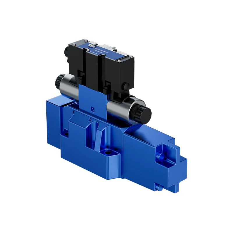
The 4WRKE is a two-stage proportional directional valve with main-spool position feedback and integrated electronics. The pilot stage and main stage must be considered together when matching the valve to the required flow range and dynamic response.
- Two-stage pilot-operated construction
- Main-spool electrical position feedback
- Integrated electronics (OBE)
- Spring-centered main spool
PRANCE HYDRAULIC · PRODUCT SERIES
cURL Too many subrequests by single Worker invocation. To configure this limit, refer to https://developers.cloudflare.com/workers/wrangler/configuration/#limits
Two-stage pilot-operated valve; main-spool position feedback · Subplate mounting; confirm pilot and drain configuration
The 4WRKE is a two-stage proportional directional valve with main-spool position feedback and integrated electronics. The pilot stage and main stage must be considered together when matching the valve to the required flow range and dynamic response.
Model
✓
Request a QuotationVer Datos Técnicos y Ficha Técnica4WRKETwo-stage pilot-operated valve; main-spool position feedback
Confirm the complete model and approved specification with Prance Hydraulic. Product-series references alone do not establish interchangeability.
Configuration review · Technical documentation · Product selection
Detalles del producto
- Two-stage pilot-operated construction
- Main-spool electrical position feedback
- Integrated electronics (OBE)
- Spring-centered main spool
CATEGORIES: Válvula hidráulica, Válvula proporcional
4WRKE Features & Application
Two-stage pilot-operated construction
Account for pilot or replenishment demand and the relevant pressure limits. Include filtration and the return or drain route in the circuit review.
Main-spool electrical position feedback
Spool feedback concerns the valve position. Confirm whether the machine also requires separate actuator position or pressure feedback.
Integrated electronics (OBE)
Match the complete control option and its command requirements to the existing controller. Similar housings can use different control arrangements.
Spring-centered main spool
Specify the full MS order code, installation drawing and operating duty so the quotation can identify the proposed configuration.
4WRKE Specifications
| Series / model | 4WRKE |
|---|---|
| Product type | cURL Too many subrequests by single Worker invocation. To configure this limit, refer to https://developers.cloudflare.com/workers/wrangler/configuration/#limits |
| Diseño | Two-stage pilot-operated valve; main-spool position feedback |
| Circuit / selection | Subplate mounting; confirm pilot and drain configuration |
| Published nominal sizes | 10, 16, 25, 27, 32 and 35 |
| Electronics | Integrated OBE; confirm command interface |
4WRKE Selection & Configuration
The 4WRKE is a two-stage proportional directional valve with main-spool position feedback and integrated electronics. The pilot stage and main stage must be considered together when matching the valve to the required flow range and dynamic response.
Supply the pilot-pressure source and drain route as well as the main circuit pressure. Check whether the quoted flow is measured at the same pressure drop as your application, and confirm the command input and connector rather than assuming all OBE variants are equivalent.

cURL Too many subrequests by single Worker invocation. To configure this limit, refer to https://developers.cloudflare.com/workers/wrangler/configuration/#limits.
cURL Too many subrequests by single Worker invocation. To configure this limit, refer to https://developers.cloudflare.com/workers/wrangler/configuration/#limits.
Hydraulic pumps · Hydraulic motors · Hydraulic valves
Send the MS nameplate, operating requirements and installation drawing for a configuration review before quoting.
- Model review — send the full model code or an existing nameplate photograph.
- Interface matching — confirm shaft, mounting flange, rotation and ports.
- Operating conditions — provide flow, pressure, speed, fluid and duty cycle.
- Documentation — request the relevant product data and drawings for your review.

4WRKE Buying Guide
Use this sequence to prepare the 4WRKE configuration for review and quotation.
- Select the circuit symbol and required de-energized spool position.
- State working flow, pressure and the pressure-drop condition for rated flow.
- Review spool overlap and command behavior during startup and switch-off.
- Confirm nominal size, subplate pattern, port and seal requirements.
- Match supply voltage, command input, connector and pin assignment.
- Review pilot supply, drain and feedback where the selected valve uses them.
- Approve the exact valve code, circuit drawing, quantity and documentation.

Selection, Documentation & Project Support

Selection Support
Learn more →Share your hydraulic circuit, operating point and installation requirements for a configuration discussion.
Flow · Pressure · Speed · Interfaces

Technical Resources
Learn more →Review product documentation, model codes and technical data before finalizing the specification.
Datasheets · Model codes · Drawings

Project Inquiries
Learn more →Send your required model, quantity, application and project requirements to discuss your inquiry.
Product inquiries · Configuration review
Configuration, Quantity & Delivery
Confirm the complete MS code, approved drawing and operating limits. Availability, quantity, documentation and delivery date are confirmed in the quotation.
Discuss Your 4WRKE Application
Send the full model code, operating duty, installation details and quantity.
Request a 4WRKE Quotation4WRKE Questions Before Ordering
What type of product is the 4WRKE?
4WRKE Proportional Valve with Integrated Electronics. Design: Two-stage pilot-operated valve; main-spool position feedback. Subplate mounting; confirm pilot and drain configuration. Confirm the complete order code for the offered version.
Can a similar valve replace the 4WRKE?
cURL Too many subrequests by single Worker invocation. To configure this limit, refer to https://developers.cloudflare.com/workers/wrangler/configuration/#limits.
cURL Too many subrequests by single Worker invocation. To configure this limit, refer to https://developers.cloudflare.com/workers/wrangler/configuration/#limits
Select the circuit symbol and required de-energized spool position. State working flow, pressure and the pressure-drop condition for rated flow. Attach the nameplate, complete order code, installation drawing and required quantity.
4WRKE Technical Data & Documents
View 4WRKE catalog data and operating conditions
cURL Too many subrequests by single Worker invocation. To configure this limit, refer to https://developers.cloudflare.com/workers/wrangler/configuration/#limits.
Datos técnicos
(para aplicaciones fuera de estos parámetros, ¡consúltenos!)general
| Tallas | Tamaño | 10 | 16 | 25 | 27 | 32 | 35 |
| Información sobre la posición de instalación y la puesta en marcha | Preferiblemente horizontal, ver RE 07800 | ||||||
| Rango de temperatura de almacenamiento | ℃ | -20 a +80 | |||||
| Rango de temperatura ambiente | ℃ | -20 a +50 | |||||
| Peso | kg | 8.7 | 11.2 | 16.8 | 17 | 31.5 | 34 |
| Ensayo de vibraciones sinusoidales según DIN EN 60068-2-6:2008 1) | 10 cycles, 10…2,000..10 Hz with logarithmic frequency changing speed of 1 oct./min, 5 to 57 Hz, amplitude 1.5 mm (p-p), 57 to 2,000 Hz, amplitude 10 g, 3 axes | ||||||
| Prueba aleatoria según DIN EN 60068-2-64:2009 1) | 20..2000 Hz, amplitud 0,05 g2/Hz (10 gRMS) 3 axes, testing time 30 min per axis | ||||||
| Ensayo de choque según la norma DIN EN 60068-2-27:2010 1) | Half sine 15 g/11 ms, 3 times in positive and 3 times in negative direction per axis, 3 axes | ||||||
| Calor húmedo, cíclico según DIN EN 60068-2-30:2006 | Variant 2 +25 ℃ to +55 ℃, 90% to 97% relative humidity, 2 cycles with 24 hours each | ||||||
hidráulico (medido a p = 100 bar con HLP46 a 40 ℃ ± 5 ℃)
| Operating pressure | Válvula de control piloto | Suministro de aceite piloto | bar | 25 a 315 | |||||
| Válvula principal, conexión P, A, B | bar | Hasta 315 | Hasta 350 | Hasta 350 | Hasta 210 | Hasta 350 | Hasta 350 | ||
| Return flow pressure | Conexión T | Drenaje de aceite piloto, | bar | Estática < 10 (válvula de control piloto) | |||||
| interno | bar | ||||||||
| Drenaje de aceite piloto, | bar | Hasta 315 | Hasta 250 | Hasta 250 | Hasta 210 | Hasta 250 | Hasta 250 | ||
| interno | bar | ||||||||
| Conexión Y | bar | Estática < 10 (válvula de control piloto) | |||||||
| Caudal nominal qVnom ± 10% con Δp = 10 bar; Δp = diferencial de presión de la válvula | l/min | - | 125 | - | - | - | - | ||
| 25 | 150 | - | - | - | - | ||||
| 50 | 200 | 220 | - | 400 | - | ||||
| 100 | 220 | 350 | 500 | 600 | 1000 | ||||
| Caudal máximo recomendado | l/min | 170 | 460 | 870 | 1000 | 1600 | 3000 | ||
| Caudal de aceite piloto en los puertos X y/o Y con una señal de entrada escalonada de 0 a 100% (315 bar) | l/min | 4.1 | 8.5 | 11.7 | 11.7 | 13.0 | 13.0 | ||
| Fluido hidráulico | Véase la tabla de la página 7 | ||||||||
| Grado máximo admisible de contaminación del fluido hidráulico, clase de limpieza según ISO 4406 (c) | Válvula de control piloto: Clase 17/15/12 1) Escenario principal: Clase 20/18/15 1) | ||||||||
| Rango de temperatura del fluido hidráulico | ℃ | -20 a +80, preferiblemente de +40 a +50 | |||||||
| Rango de viscosidad | mm2/s | 20 a 380, preferiblemente 30 a 45 | |||||||
| Histéresis | % | ≤ 1 | |||||||
| Sensibilidad de respuesta | % | ≤ 0.5 | |||||||
| Fluido hidráulico | Clasificación | Suitable sealing materials | Estándares | |
| Aceites minerales y hidrocarburos relacionados | HL, HLP | NBR, FKM | DIN 51524 | |
| Resistente a las llamas | -que contiene agua | HFC (Fuchs HYDROTHERM 46M, Petrofer Ultra Safe 620) | NBR | ISO 12922 |
| Éster de ácido fosfórico | HFD-R | FKM | ||
| Important information on hydraulic fluids! -For more information and data on the use of other hydraulic fluids refer to data sheet 90220 or contact us! -There may be limitations regarding the technical valve data (temperature, pressure range, life cycle, maintenance intervals, etc.)! -The flash point of the process and operating medium used must be 40 K greater than the maximum solenoid surface temperature. – Flame-resistant- containing water: Maximum pressure differential per control edge 175 bar. Pressure pre-loading at the tank port > 20% of the pressure differential; otherwise, increased cavitation. – Life cycle as compared to operation with mineral oil HL,HLP 50% to 100% | ||||
Eléctrico
| Tipo de voltaje | Tensión continua |
| Tipo de señal | Análogo |
| Potencia máxima W | 72 (promedio = 24 W) |
| Conexión eléctrica | Conector hembra según DIN EN 175201-804 |
| Clase de protección de la válvula según EN 60529 | IP65 con el conector acoplado, montado y bloqueado |
| Electrónica de control | Integrado en la válvula, ver página 8 |
| Asignación de pines del conector | Contacto | Señales con A1 | Señal con F1 | Señal con A5 |
| Tensión de alimentación | A | 24 VCC (18 a 35 VCC); Imáx= 1,5 A; carga de impulso ≤ 3 A | ||
| B | 0 V | |||
| Referencia (valor real) | C | Reference potential for actual value (contact “F”) | Habilitar 4 a 24 V | |
| Entrada del amplificador diferencial | D | ±10 V | de 4 a 20 mA | ±10 V |
| Valor del comando | E | Potencial de referencia de 0 V al pin D | Potencial de referencia de 0 V para los pines D y F | |
| Medición de la producción (valor real) | F | ±10 V | de 4 a 20 mA | ±10 V |
| PE | Conectado al elemento de refrigeración y al cuerpo de la válvula | |||
Valor del comando:
Reference potential at E and positive command value at D result in flow from P→A and B→T. Reference potential at E and negative command value at D result in flow from P→B and A→ T.Cable de conexión:
Recommendation: – Up to 25 m line length: Type LiYCY 7×0.75 mm2 – Up to 50 m line length: Type LiYCY 7× 1.0 mm2 Conecte el blindaje a PE únicamente en el lado de la alimentación.Aviso:
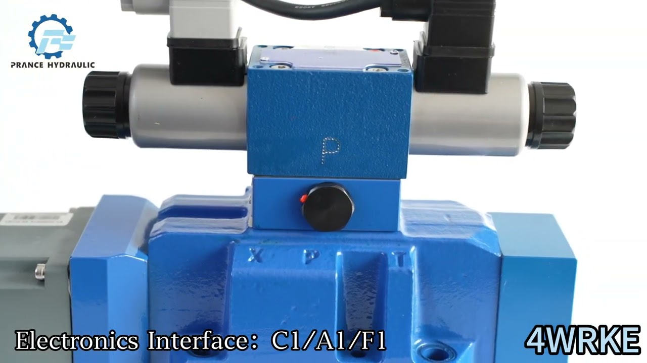
Las señales eléctricas extraídas a través de la electrónica de la válvula (p. ej., valor real) no deben utilizarse para desconectar funciones de la máquina relevantes para la seguridad.Watch 4WRKE Product Video
Related Selection Resources
Request a 4WRKE Quotation
Tell us your required configuration, quantity and application.
Productos relacionados
cURL Too many subrequests by single Worker invocation. To configure this limit, refer to https://developers.cloudflare.com/workers/wrangler/configuration/#limits.
Datos técnicos
(para aplicaciones fuera de estos parámetros, ¡consúltenos!)
general
| Tallas | Tamaño | 10 | 16 | 25 | 27 | 32 | 35 |
| Información sobre la posición de instalación y la puesta en marcha | Preferiblemente horizontal, ver RE 07800 | ||||||
| Rango de temperatura de almacenamiento | ℃ | -20 a +80 | |||||
| Rango de temperatura ambiente | ℃ | -20 a +50 | |||||
| Peso | kg | 8.7 | 11.2 | 16.8 | 17 | 31.5 | 34 |
| Ensayo de vibraciones sinusoidales según DIN EN 60068-2-6:2008 1) | 10 ciclos, 10...2000...10 Hz con frecuencia logarítmica cambiando la velocidad de 1 oct./min, 5 a 57 Hz, amplitud de 1,5 mm (p-p), 57 a 2000 Hz, amplitud 10 g, 3 ejes |
||||||
| Prueba aleatoria según DIN EN 60068-2-64:2009 1) | 20..2000 Hz, amplitud 0,05 g2/Hz (10 gRMS) 3 ejes, tiempo de prueba 30 min por eje |
||||||
| Ensayo de choque según la norma DIN EN 60068-2-27:2010 1) | media onda senoidal 15 g/11 ms, 3 veces en sentido positivo y 3 veces en dirección negativa por eje, 3 ejes |
||||||
| Calor húmedo, cíclico según DIN EN 60068-2-30:2006 | Variante 2 De +25 ℃ a +55 ℃, de 90% a 97% de humedad relativa, 2 ciclos de 24 horas cada uno |
||||||
1)La información sobre la carga mecánica se aplica al nivel de fijación de la electrónica de válvula integrada.
hidráulico (medido a p = 100 bar con HLP46 a 40 ℃ ± 5 ℃)
| Funcionamiento presión |
Válvula de control piloto | Suministro de aceite piloto | bar | 25 a 315 | |||||
| Válvula principal, conexión P, A, B | bar | Hasta 315 | Hasta 350 | Hasta 350 | Hasta 210 | Hasta 350 | Hasta 350 | ||
| Flujo de retorno presión |
Conexión T | Drenaje de aceite piloto, | bar | Estática < 10 (válvula de control piloto) | |||||
| interno | bar | ||||||||
| Drenaje de aceite piloto, | bar | Hasta 315 | Hasta 250 | Hasta 250 | Hasta 210 | Hasta 250 | Hasta 250 | ||
| interno | bar | ||||||||
| Conexión Y | bar | Estática < 10 (válvula de control piloto) | |||||||
| Caudal nominal qVnom ± 10% con Δp = 10 bar; Δp = diferencial de presión de la válvula | l/min | - | 125 | - | - | - | - | ||
| 25 | 150 | - | - | - | - | ||||
| 50 | 200 | 220 | - | 400 | - | ||||
| 100 | 220 | 350 | 500 | 600 | 1000 | ||||
| Caudal máximo recomendado | l/min | 170 | 460 | 870 | 1000 | 1600 | 3000 | ||
| Caudal de aceite piloto en los puertos X y/o Y con una señal de entrada escalonada de 0 a 100% (315 bar) | l/min | 4.1 | 8.5 | 11.7 | 11.7 | 13.0 | 13.0 | ||
| Fluido hidráulico | Véase la tabla de la página 7 | ||||||||
| Grado máximo admisible de contaminación del fluido hidráulico - clase de limpieza según ISO 4406 (c) | Válvula de control piloto: Clase 17/15/12 1) Escenario principal: Clase 20/18/15 1) |
||||||||
| Rango de temperatura del fluido hidráulico | ℃ | -20 a +80, preferiblemente de +40 a +50 | |||||||
| Rango de viscosidad | mm2/s | 20 a 380, preferiblemente 30 a 45 | |||||||
| Histéresis | % | ≤ 1 | |||||||
| Sensibilidad de respuesta | % | ≤ 0.5 | |||||||
1) Las clases de limpieza especificadas para los componentes deben mantenerse en los sistemas hidráulicos. Una filtración eficaz previene fallos y, al mismo tiempo, aumenta el ciclo de vida de los componentes. Para la selección de los filtros, consulte www.boschrexroth.com/filter
| Fluido hidráulico | Clasificación | Adecuado materiales de sellado |
Estándares | |
| Aceites minerales y hidrocarburos relacionados | HL, HLP | NBR, FKM | DIN 51524 | |
| Resistente a las llamas | -que contiene agua | HFC (Fuchs HYDROTHERM 46M, Petrofer Ultra Safe 620 |
NBR | ISO 12922 |
| Éster de ácido fosfórico | HFD-R | FKM | ||
| ¡Información importante sobre los fluidos hidráulicos! -Para obtener más información y datos sobre el uso de otros fluidos hidráulicos, consulte la hoja de datos 90220 o ¡póngase en contacto con nosotros! -¡Puede haber limitaciones con respecto a los datos técnicos de la válvula (temperatura, rango de presión, ciclo de vida, intervalos de mantenimiento, etc.)! El punto de inflamación del proceso y del medio de funcionamiento utilizado debe ser 40 K superior a la temperatura máxima de la superficie del solenoide. - Resistente al fuego y con agua: diferencia de presión máxima por borde de control de 175 bar. Precarga de presión en la toma del depósito > 20% de la diferencia de presión; de lo contrario, se producirá un aumento de la cavitación. - Ciclo de vida en comparación con el funcionamiento con aceite mineral HL, HLP 50% a 100% |
||||
Eléctrico
| Tipo de voltaje | Tensión continua |
| Tipo de señal | Análogo |
| Potencia máxima W | 72 (promedio = 24 W) |
| Conexión eléctrica | Conector hembra según DIN EN 175201-804 |
| Clase de protección de la válvula según EN 60529 | IP65 con el conector acoplado, montado y bloqueado |
| Electrónica de control | Integrado en la válvula, ver página 8 |
| Asignación de pines del conector | Contacto | Señales con A1 | Señal con F1 | Señal con A5 |
| Tensión de alimentación | A | 24 VCC (18 a 35 VCC); Imáx= 1,5 A; carga de impulso ≤ 3 A | ||
| B | 0 V | |||
| Referencia (valor real) | C | Potencial de referencia para valor real (contacto "F") | Habilitar 4 a 24 V | |
| Entrada del amplificador diferencial | D | ±10 V | de 4 a 20 mA | ±10 V |
| Valor del comando | E | Potencial de referencia de 0 V al pin D | Potencial de referencia de 0 V para los pines D y F | |
| Medición de la producción (valor real) | F | ±10 V | de 4 a 20 mA | ±10 V |
| PE | Conectado al elemento de refrigeración y al cuerpo de la válvula | |||
Valor del comando:
El potencial de referencia en E y el valor de comando positivo en D dan como resultado un flujo de P→A y B→T.
El potencial de referencia en E y el valor de comando negativo en D dan como resultado un flujo de P→B y A→T.
Cable de conexión:
Recomendación: - Hasta 25 m de longitud de línea: Tipo LiYCY 7×0,75 mm2
- Hasta 50 m de longitud de línea: Tipo LiYCY 7 × 1,0 mm2
Conecte el blindaje a PE únicamente en el lado de la alimentación.
Aviso:
Las señales eléctricas extraídas a través de la electrónica de la válvula (p. ej., valor real) no deben utilizarse para desconectar funciones de la máquina relevantes para la seguridad.
