Wenzhou Prance Hydraulic Equipment Co., Ltd

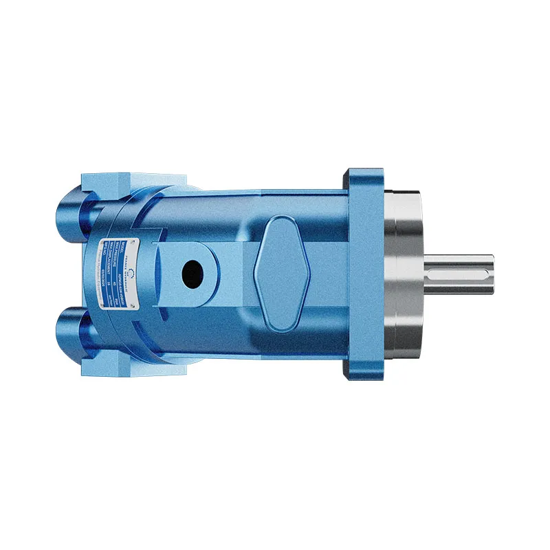


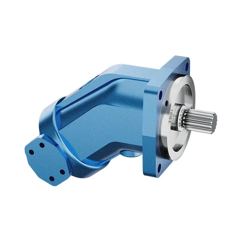
A2FM Fixed Displacement Bent Axis Motor
The A2FM fixed displacement motor converts hydraulic flow and pressure difference into shaft speed and torque. It is listed for open and closed circuits, provided the selected model meets the circuit pressure, drainage and installation conditions.
- Fixed displacement motor
- Bent-axis piston design
- Mobile and industrial applications
- Size and interfaces selected from the model code
PRANCE HYDRAULIC · PRODUCT SERIES
A2FM Fixed Displacement Bent Axis Motor
Axial piston; bent axis, fixed displacement · Open and closed circuits, subject to configuration
The A2FM fixed displacement motor converts hydraulic flow and pressure difference into shaft speed and torque. It is listed for open and closed circuits, provided the selected model meets the circuit pressure, drainage and installation conditions.
Modèle
✓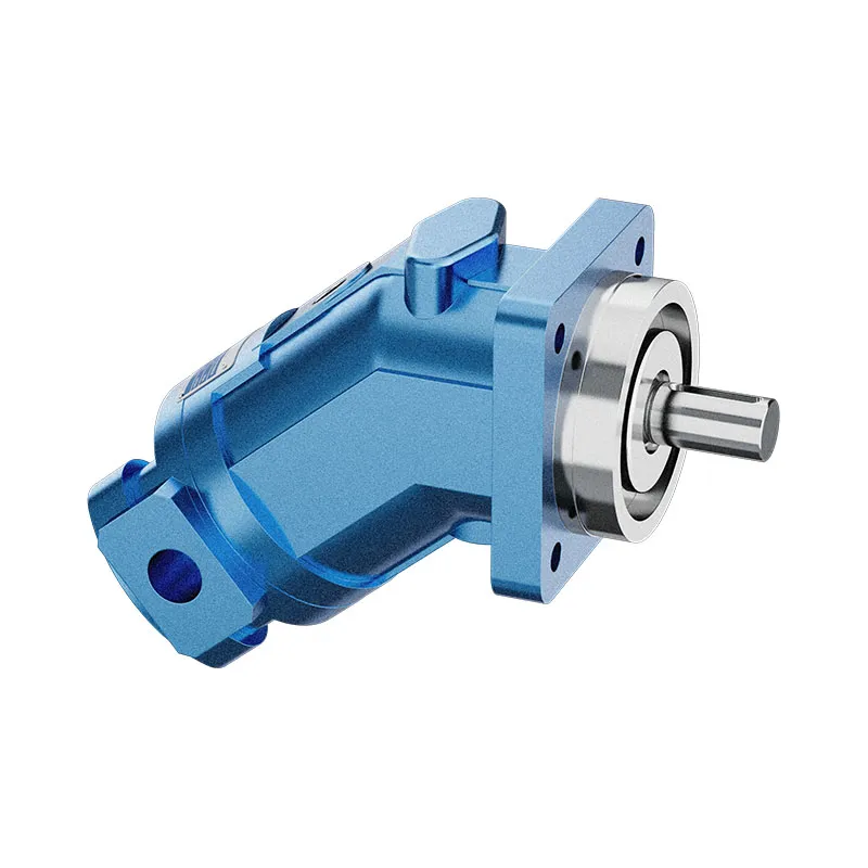
Demander un devisVoir les données techniques et la fiche techniqueA2FMAxial piston; bent axis, fixed displacement
Confirm the complete model and approved specification with Prance Hydraulic. Product-series references alone do not establish interchangeability.
Étude de configuration · Documentation technique · Sélection de produits
Détails du produit
- Fixed displacement motor
- Bent-axis piston design
- Mobile and industrial applications
- Size and interfaces selected from the model code
CATÉGORIES : Moteur à cylindrée fixe, Moteur à pistons
A2FM Features & Application
Fixed displacement motor
For a fixed displacement, flow and speed remain linked by the selected displacement. Check the actual operating point and efficiency.
Bent-axis piston design
Specify the full MS order code, installation drawing and operating duty so the quotation can identify the proposed configuration.
Mobile and industrial applications
Check the required shaft torque and speed at the same operating point. Include starting duty, return pressure and external shaft loads.
Size and interfaces selected from the model code
Check pilot diameter, bolt pattern, shaft engagement or port pattern against the approved installation drawing.
A2FM Specifications
| Series / model | A2FM |
|---|---|
| Product type | A2FM Fixed Displacement Bent Axis Motor |
| Conception | Axial piston; bent axis, fixed displacement |
| Circuit / selection | Open and closed circuits, subject to configuration |
| Contrôle du déplacement | Fixed |
| Huile hydraulique | Mineral-oil use described; confirm other fluids and seal options individually |
A2FM Selection & Configuration
The A2FM fixed displacement motor converts hydraulic flow and pressure difference into shaft speed and torque. It is listed for open and closed circuits, provided the selected model meets the circuit pressure, drainage and installation conditions.
Choose displacement from the required torque-speed duty and available flow, then check external shaft loads and case pressure. Increasing supply pressure alone does not establish safe operation if the return or drain is restricted. Use the selected model data for continuous and peak conditions.
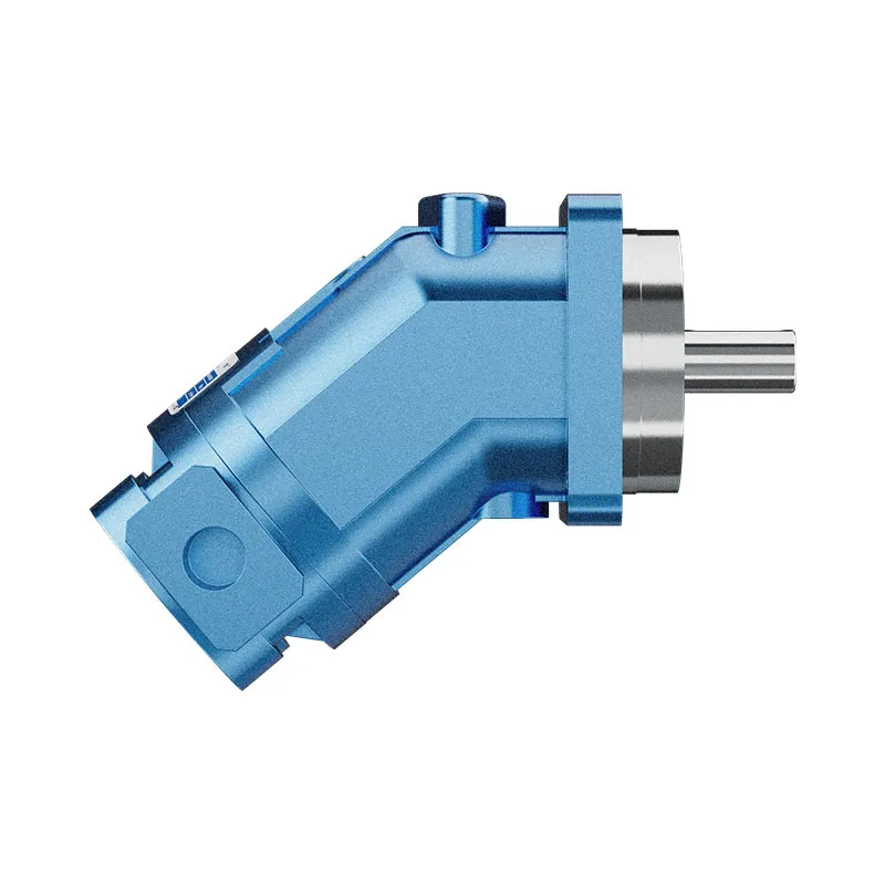
Your Application.
The Right Configuration.
Hydraulic pumps · Hydraulic motors · Hydraulic valves
Send the MS nameplate, operating requirements and installation drawing for a configuration review before quoting.
- Model review — send the full model code or an existing nameplate photograph.
- Interface matching — confirm shaft, mounting flange, rotation and ports.
- Operating conditions — provide flow, pressure, speed, fluid and duty cycle.
- Documentation — request the relevant product data and drawings for your review.

A2FM Buying Guide
Use this sequence to prepare the A2FM configuration for review and quotation.
- Define starting and continuous torque, speed range and duty cycle.
- Specify available flow, work-port pressure difference and return pressure.
- Confirm the displacement setting and required behavior during starting and stopping.
- Check shaft, mounting pilot, flange, port orientation and external loads.
- Review case drainage, replenishment and any displacement control.
- Specify fluid conditions and any independent braking requirement.
- Approve the complete model, operating envelope, drawing and quantity.

Selection, Documentation & Project Support

Selection Support
Learn more →Share your hydraulic circuit, operating point and installation requirements for a configuration discussion.
Flow · Pressure · Speed · Interfaces

Technical Resources
Learn more →Review product documentation, model codes and technical data before finalizing the specification.
Datasheets · Model codes · Drawings

cURL Too many subrequests by single Worker invocation. To configure this limit, refer to https://developers.cloudflare.com/workers/wrangler/configuration/#limits
Learn more →cURL Too many subrequests by single Worker invocation. To configure this limit, refer to https://developers.cloudflare.com/workers/wrangler/configuration/#limits.
cURL Too many subrequests by single Worker invocation. To configure this limit, refer to https://developers.cloudflare.com/workers/wrangler/configuration/#limits
Configuration, Quantity & Delivery
Confirm the complete MS code, approved drawing and operating limits. Availability, quantity, documentation and delivery date are confirmed in the quotation.
Discuss Your A2FM Application
Send the full model code, operating duty, installation details and quantity.
Request a A2FM QuotationA2FM Questions Before Ordering
What type of product is the A2FM?
AA2FM Fixed Displacement Bent Axis Motor. Design: Axial piston; bent axis, fixed displacement. Open and closed circuits, subject to configuration. Confirm the complete order code for the offered version.
Can a similar motor replace the A2FM?
cURL Too many subrequests by single Worker invocation. To configure this limit, refer to https://developers.cloudflare.com/workers/wrangler/configuration/#limits.
cURL Too many subrequests by single Worker invocation. To configure this limit, refer to https://developers.cloudflare.com/workers/wrangler/configuration/#limits
cURL Too many subrequests by single Worker invocation. To configure this limit, refer to https://developers.cloudflare.com/workers/wrangler/configuration/#limits.
A2FM Technical Data & Documents
View A2FM catalog data and operating conditions
cURL Too many subrequests by single Worker invocation. To configure this limit, refer to https://developers.cloudflare.com/workers/wrangler/configuration/#limits.
Données techniques
Huile hydraulique
Le moteur à déplacement fixe A2FM est adapté à une utilisation avec de l'huile minérale.Plage de viscosité
We recommend that a viscosity (at operating temperature)for optimum efficiency and service life purposes of Vopt= optimum viscosity 16…36mm2Soyez choisi, en tenant compte de la température de circulation (circuit fermé) et de la température du réservoir (circuit ouvert).Limites de la plage de viscosité
The following values apply extreme cases: Vmin=5mm2/s short term(t < 3 min) at max. permitted temperature tmax=115℃ Vmax=1600mm2/s short term (t<3 min) with cold start(P<3MPa, n≤1000rpm tminÀ noter que la température maximale du fluide hydraulique ne doit pas non plus être dépassée localement (par ex. zone de palier). Selon la pression et la vitesse, la température dans la zone de palier est supérieure de 12 K maximum à la température moyenne de fuite de carter.Diagramme de sélection
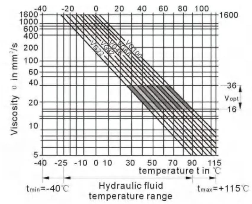
Détails concernant le choix du fluide hydraulique
The correct choice of pressure fluid requires knowledge of the operating temperature in relation to the ambient temperature:in a closed circuit the circulation temperature,in an open circuit the tank temperature. The hydraulic fluid should be selected so that within the operating temperature range,the operating viscosity lies within the optimum range (υ opt) (see shaded section of the selection diagram).We recommend that the highest possible viscosity range should be chosen in each case. Example:At an ambient temperature of X℃ an operating temperature of 60℃ is set in the circuit . In the optimum operating viscosity range (υ opt; shaded area) this corresponds to the viscosity classes VG 46 or VG68; to be selected: CG 68 Please note : The leakage fluid temperature, which is affected by pressure and rotational speed, is always higher than the circulation temperature or tank temperature. At no point in the system may t-he temperature be higher than 115℃.Filtration
The finer the filtration, the cleaner the fluid and the longer the service life of the axial piston unit. To ensure proper function of the axial piston unit, the hydraulic fluid must have a cleanliness level of least. 20/18/15 according to ISO 4406. At very high hydraulic fluid temperatures (90℃ to max. 115℃),a cleanliness level of at least. 19/17/14 according to ISO 4406 is required. Please contact us if these cleanliness levels cannot be achieved. Plage de pression de service Maximum pressure on port A or B (pressure data according to DIN 24312)| Extrémité d'arbre A,Z | Extrémité d'arbre B, P | |
| Pression nominale PN | 40 MPa | 35 MPa |
| Pression de crête Pmax | 45 MPa | 40 MPa |
| Pression de sommation (A+B) | 70 MPa | 70 MPa |
Sens de circulation
Speed rang
No limit to minimum speed nmin. If uniform motion is required,nmin must not be less than 50 rpm.Shaft seal ring
permissible pressure load The pressure service life of the shaft seal ring is affected by the speed of the motor and the case drain pressure. The permitted loading with intermittent case drain pressure depends on the rotational speed(see chart). Short-term (t<5 min) pressure spikes of up to 1 Mpa absolute are permitted. The average permanent case drain pressure must not exceed 0. 3Mpa absolute. The pressure in the case must be equal to or greater than the external pressure on the shaft seal.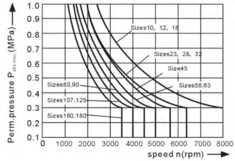
Temperature range
The FKM shaft seal is admissible for a housing temperature range from -25℃ to +115℃Table of values (theoretical values, ignoring ηmin et ηv; values rounded)
| Taille | 10 | 12 | 16 | 23 | 28 | 32 | 45 | |||
| Déplacement | Vg | mL/r | 10.3 | 12.0 | 16.0 | 22.9 | 28.1 | 32 | 45.6 | |
| Speed max | nmax | min-1 | 8000 | 8000 | 8000 | 6300 | 6300 | 6300 | 5600 | |
| nmax limit1) | min-1 | 8800 | 8800 | 8800 | 6900 | 6900 | 6900 | 6200 | ||
| Flow max. | qvmax | L/min | 82 | 96 | 128 | 144 | 176 | 201 | 255 | |
| Torque constants | TK | Nm/MPa | 1.64 | 1.9 | 2.5 | 3.6 | 4.45 | 5.09 | 7.25 | |
| Torque at | Δp=35 MPa | T | Rien | 57 | 67 | 88 | 126 | 156 | 178 | 254 |
| Δp=40 MPa | T | Rien | 65 | 76 | 100 | 144 | 178 | 204 | 290 | |
| Filling capacity | L | 0.17 | 0.17 | 0.17 | 0.20 | 0.20 | 0.20 | 0.33 | ||
| Mass moment of inertia around output shaft | J | kgm2 | 0.0004 | 0.0004 | 0.0004 | 0.0012 | 0.0012 | 0.0012 | 0.0024 | |
| Mass(approx.) | kg | 5.4 | 5.4 | 5.4 | 9.5 | 9.5 | 9.5 | 13.5 | ||
| Taille | 56 | 63 | 80 | 90 | 107 | 125 | 160 | 180 | |||
| Déplacement | Vg | mL/r | 56.1 | 63.0 | 80.4 | 90.0 | 106.7 | 125.0 | 160.4 | 180.0 | |
| Speed max | nmax | min-1 | 5000 | 5000 | 4500 | 4500 | 4000 | 4000 | 3600 | 3600 | |
| nmax limit1) | min-1 | 5500 | 5500 | 5000 | 5000 | 4400 | 4400 | 4000 | 4000 | ||
| Flow max. | qvmax | L/min | 280 | 315 | 360 | 405 | 427 | 500 | 577 | 648 | |
| Torque constants | TK | Nm/MPa | 8.9 | 10.0 | 12.7 | 17.0 | 19.9 | 25.4 | 28.6 | 31.8 | |
| Torque at | Δp=35 MPa | T | Rien | 312 | 350 | 445 | 501 | 595 | 697 | 889 | 1001 |
| Δp=40 MPa | T | Rien | 356 | 400 | 508 | 572 | 680 | 796 | 1016 | 1144 | |
| Filling capacity | L | 0.45 | 0.45 | 0.55 | 0.55 | 0.8 | 0.80 | 1.1 | 1.1 | ||
| Mass moment of inertia around output shaft | J | kgm2 | 0.0042 | 0.0042 | 0.0072 | 0.0072 | 0.0116 | 0.0116 | 0.0220 | 0.0220 | |
| Mass(approx.) | kg | 18 | 18 | 23 | 23 | 32 | 32 | 45 | 45 | ||
Determining the size
| Flux | qv=(VgcURL Too many subrequests by single Worker invocation. To configure this limit, refer to https://developers.cloudflare.com/workers/wrangler/configuration/#limitsv) | [L/min] | Vg=Displacement per revolution in mL/r Δp=Differential pressure in MPa n=Speed in rpm ηv=Volumetric efficiency ηhm=Mechanical-hydraulic efficiency ηt=Overall efficiency |
| speed | n=(qv∙1000∙ηv)/Vg | [rpm] | |
| Couple | T=(Vg∙ Δp∙ηhm)/20π | [Nm] | |
| Puissance | P=(2π∙T∙n)/60000=(qvcURL Too many subrequests by single Worker invocation. To configure this limit, refer to https://developers.cloudflare.com/workers/wrangler/configuration/#limits | cURL Too many subrequests by single Worker invocation. To configure this limit, refer to https://developers.cloudflare.com/workers/wrangler/configuration/#limits |
| Taille | 10 | 12 | 16 | 23 | 28 | 32 | 45 | 56 | |||
| cURL Too many subrequests by single Worker invocation. To configure this limit, refer to https://developers.cloudflare.com/workers/wrangler/configuration/#limits.1) at distance a (from shaft collar) | 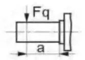 |
Fqmax | N | 2350 | 2750 | 3700 | 4300 | 5400 | 6100 | 81502) | 92002) |
| a | mm | 16 | 16 | 16 | 16 | 16 | 16 | 18 | 18 | ||
| Force axiale, max.3) | 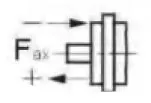 |
+Fax max | N | 320 | 320 | 320 | 500 | 500 | 500 | 630 | 800 |
| -Fax max | N | 320 | 320 | 320 | 500 | 500 | 500 | 630 | 800 | ||
| Permissible axial force/MPa operating pressure | ±Fax per/MPa | N/MPa | 30 | 30 | 30 | 52 | 52 | 52 | 70 | 87 | |
| Taille | 63 | 80 | 90 | 107 | 125 | 160 | 180 | |||
| cURL Too many subrequests by single Worker invocation. To configure this limit, refer to https://developers.cloudflare.com/workers/wrangler/configuration/#limits.1) at distance a (from shaft collar) | 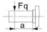 |
Fqmax | N | 10300 | 115002) | 12900 | 13600 | 15900 | 18400 | 20600 |
| a | mm | 18 | 20 | 20 | 20 | 20 | 25 | 25 | ||
| Force axiale, max.3) | 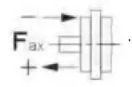 |
+Fax max | N | 800 | 1000 | 1000 | 12500 | 1250 | 1600 | 1600 |
| -Fax max | N | 800 | 1000 | 1000 | 12500 | 1250 | 1600 | 1600 | ||
| Permissible axial force/MPa operating pressure | ±Fax per/MPa | N/MPa | 87 | 106 | 106 | 129 | 129 | 167 | 167 | |
Minimum inlet pressure on service line port A(B)
In order to avid damage of the motor a minimum inlet pressure at the inlet zone must be assured. The minimum inlet pressure is related to the rotational speed of the fixed motor.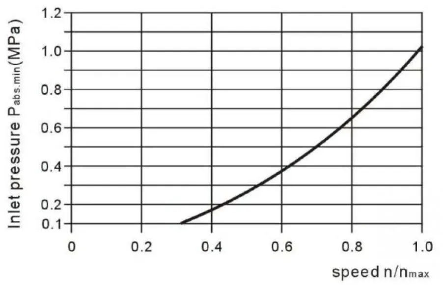 Please contact us if these conditions cannot be satisfied.
Related Selection Resources
Request a A2FM Quotation
Tell us your required configuration, quantity and application.
Produits associés
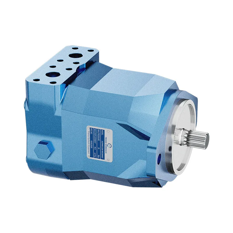
Compare related hydraulic motors and confirm the complete configuration for your application.


Données techniques
Huile hydraulique
Le moteur à déplacement fixe A2FM est adapté à une utilisation avec de l'huile minérale.
Plage de viscosité
Nous recommandons qu'une viscosité (à la température de fonctionnement) pour une performance optimale
efficacité et durée de vie pour des raisons d'efficacité et de service
Voptviscosité optimale 16...36mm2/s
Soyez choisi, en tenant compte de la température de circulation (circuit fermé) et de la température du réservoir (circuit ouvert).
Limites de la plage de viscosité
Les valeurs suivantes s'appliquent à des cas extrêmes :
Vmin=5mm2/s
température maximale autorisée à court terme (t < 3 min)
tmax=115℃
Vmax=1600mm2/s
court terme (t<3 min) avec démarrage à froid (P<3MPa),
n≤1000tr/min tmin=-40℃)
À noter que la température maximale du fluide hydraulique ne doit pas non plus être dépassée localement (par ex. zone de palier). Selon la pression et la vitesse, la température dans la zone de palier est supérieure de 12 K maximum à la température moyenne de fuite de carter.
Diagramme de sélection
Détails concernant le choix du fluide hydraulique
Le choix correct du fluide sous pression nécessite la connaissance de la température de service par rapport à la température ambiante : en circuit fermé, la température de circulation, en circuit ouvert, la température du réservoir.
Le fluide hydraulique doit être choisi de telle sorte qu'à l'intérieur de la plage de température de service, la viscosité de service se situe dans la plage optimale (υ opt) (voir la zone ombrée du diagramme de sélection). Nous recommandons de choisir dans chaque cas la plage de viscosité la plus élevée possible.
Exemple : à une température ambiante de X℃, une température de service de 60℃ est établie dans le circuit. Dans la plage de viscosité de service optimale (υ opt ; zone ombrée), cela correspond aux classes de viscosité VG 46 ou VG 68 ; à sélectionner : VG 68
Remarque : La température du fluide de fuite, influencée par la pression et la vitesse de rotation, est toujours supérieure à la température de circulation ou à la température du réservoir. En aucun point du système, la température ne doit dépasser 115℃.
Filtration
Plus la filtration est fine, plus le fluide est propre et plus la durée de vie
de l'unité à pistons axiaux est longue.
Pour garantir le bon fonctionnement de l'unité à pistons axiaux, le fluide hydraulique doit présenter un niveau de propreté d'au moins.
20/18/15 selon ISO 4406.
À des températures de fluide hydraulique très élevées (90℃ à max. 115℃), un niveau de propreté d'au moins.
19/17/14 selon ISO 4406 est requis.
Veuillez nous contacter si ces niveaux de propreté ne peuvent pas être atteints.
Plage de pression de service
Pression maximale sur l'orifice A ou B
(données de pression selon DIN 24312)
| Extrémité d'arbre A,Z | Extrémité d'arbre B, P | |
| Pression nominale PN | 40 MPa | 35 MPa |
| Pression de crête Pmax | 45 MPa | 40 MPa |
| Pression de sommation (A+B) | 70 MPa | 70 MPa |
Veuillez noter : à l'extrémité d'arbre Z et P, une pression nominale de PN=31,5 MPa (Pmax=35 MPa) est autorisée pour l'extrémité d'arbre entraînée soumise à une flexion transversale (pignons, courroies en V) !
Size 56 with shaft end Z:PN=35MPa, Pmax=40MPa
in cases of pulsating loading above 31. 5MPa, we recommend the version with splined shaft A or splined shaft Z(sizes 45)
Sens de circulation
Speed rang
No limit to minimum speed nmin. If uniform motion is required,nmin must not be less than 50 rpm.
Shaft seal ring
permissible pressure load
The pressure service life of the shaft seal ring is affected by the speed of the motor and the case drain pressure. The permitted loading with intermittent case drain pressure depends on the rotational speed(see chart). Short-term (t<5 min) pressure spikes of up to 1 Mpa absolute are permitted.
The average permanent case drain pressure must not exceed 0. 3Mpa absolute.
The pressure in the case must be equal to or greater than the external pressure on the shaft seal.
Temperature range
The FKM shaft seal is admissible for a housing temperature range
from -25℃ to +115℃
Table of values (theoretical values, ignoring ηmin et ηv; values rounded)
| Taille | 10 | 12 | 16 | 23 | 28 | 32 | 45 | |||
| Déplacement | Vg | mL/r | 10.3 | 12.0 | 16.0 | 22.9 | 28.1 | 32 | 45.6 | |
| Speed max | nmax | min-1 | 8000 | 8000 | 8000 | 6300 | 6300 | 6300 | 5600 | |
| nmax limit1) | min-1 | 8800 | 8800 | 8800 | 6900 | 6900 | 6900 | 6200 | ||
| Flow max. | qvmax | L/min | 82 | 96 | 128 | 144 | 176 | 201 | 255 | |
| Torque constants | TK | Nm/MPa | 1.64 | 1.9 | 2.5 | 3.6 | 4.45 | 5.09 | 7.25 | |
| Torque at | Δp=35 MPa | T | Rien | 57 | 67 | 88 | 126 | 156 | 178 | 254 |
| Δp=40 MPa | T | Rien | 65 | 76 | 100 | 144 | 178 | 204 | 290 | |
| Filling capacity | L | 0.17 | 0.17 | 0.17 | 0.20 | 0.20 | 0.20 | 0.33 | ||
| Mass moment of inertia around output shaft |
J | kgm2 | 0.0004 | 0.0004 | 0.0004 | 0.0012 | 0.0012 | 0.0012 | 0.0024 | |
| Mass(approx.) | kg | 5.4 | 5.4 | 5.4 | 9.5 | 9.5 | 9.5 | 13.5 | ||
| Taille | 56 | 63 | 80 | 90 | 107 | 125 | 160 | 180 | |||
| Déplacement | Vg | mL/r | 56.1 | 63.0 | 80.4 | 90.0 | 106.7 | 125.0 | 160.4 | 180.0 | |
| Speed max | nmax | min-1 | 5000 | 5000 | 4500 | 4500 | 4000 | 4000 | 3600 | 3600 | |
| nmax limit1) | min-1 | 5500 | 5500 | 5000 | 5000 | 4400 | 4400 | 4000 | 4000 | ||
| Flow max. | qvmax | L/min | 280 | 315 | 360 | 405 | 427 | 500 | 577 | 648 | |
| Torque constants | TK | Nm/MPa | 8.9 | 10.0 | 12.7 | 17.0 | 19.9 | 25.4 | 28.6 | 31.8 | |
| Torque at | Δp=35 MPa | T | Rien | 312 | 350 | 445 | 501 | 595 | 697 | 889 | 1001 |
| Δp=40 MPa | T | Rien | 356 | 400 | 508 | 572 | 680 | 796 | 1016 | 1144 | |
| Filling capacity | L | 0.45 | 0.45 | 0.55 | 0.55 | 0.8 | 0.80 | 1.1 | 1.1 | ||
| Mass moment of inertia around output shaft |
J | kgm2 | 0.0042 | 0.0042 | 0.0072 | 0.0072 | 0.0116 | 0.0116 | 0.0220 | 0.0220 | |
| Mass(approx.) | kg | 18 | 18 | 23 | 23 | 32 | 32 | 45 | 45 | ||
1) intermittent maximum speed: overspeed at discharge and over-running travel operations,t<5 sec. and Δp<15MPa.
Determining the size
| Flux | qv=(VgcURL Too many subrequests by single Worker invocation. To configure this limit, refer to https://developers.cloudflare.com/workers/wrangler/configuration/#limitsv) | [L/min] | Vg=Displacement per revolution in mL/r Δp=Differential pressure in MPa n=Speed in rpm ηv=Rendement volumétrique ηhm=Efficacité mécanique-hydraulique ηt=Overall efficiency |
| speed | n=(qv∙1000∙ηv)/Vg | [rpm] | |
| Couple | T=(Vg∙ Δp∙ηhm)/20π | [Nm] | |
| Puissance | P=(2π∙T∙n)/60000=(qvcURL Too many subrequests by single Worker invocation. To configure this limit, refer to https://developers.cloudflare.com/workers/wrangler/configuration/#limits | cURL Too many subrequests by single Worker invocation. To configure this limit, refer to https://developers.cloudflare.com/workers/wrangler/configuration/#limits |
cURL Too many subrequests by single Worker invocation. To configure this limit, refer to https://developers.cloudflare.com/workers/wrangler/configuration/#limits
cURL Too many subrequests by single Worker invocation. To configure this limit, refer to https://developers.cloudflare.com/workers/wrangler/configuration/#limits
| Taille | 10 | 12 | 16 | 23 | 28 | 32 | 45 | 56 | |||
| cURL Too many subrequests by single Worker invocation. To configure this limit, refer to https://developers.cloudflare.com/workers/wrangler/configuration/#limits.1) cURL Too many subrequests by single Worker invocation. To configure this limit, refer to https://developers.cloudflare.com/workers/wrangler/configuration/#limits cURL Too many subrequests by single Worker invocation. To configure this limit, refer to https://developers.cloudflare.com/workers/wrangler/configuration/#limits |
|
Fqmax | N | 2350 | 2750 | 3700 | 4300 | 5400 | 6100 | 81502) | 92002) |
| a | mm | 16 | 16 | 16 | 16 | 16 | 16 | 18 | 18 | ||
| Force axiale, max.3) | |
+Fax max | N | 320 | 320 | 320 | 500 | 500 | 500 | 630 | 800 |
| -Fax max | N | 320 | 320 | 320 | 500 | 500 | 500 | 630 | 800 | ||
| cURL Too many subrequests by single Worker invocation. To configure this limit, refer to https://developers.cloudflare.com/workers/wrangler/configuration/#limits pression de fonctionnement |
±Fax per/MPa | N/MPa | 30 | 30 | 30 | 52 | 52 | 52 | 70 | 87 | |
| Taille | 63 | 80 | 90 | 107 | 125 | 160 | 180 | |||
| cURL Too many subrequests by single Worker invocation. To configure this limit, refer to https://developers.cloudflare.com/workers/wrangler/configuration/#limits.1) cURL Too many subrequests by single Worker invocation. To configure this limit, refer to https://developers.cloudflare.com/workers/wrangler/configuration/#limits cURL Too many subrequests by single Worker invocation. To configure this limit, refer to https://developers.cloudflare.com/workers/wrangler/configuration/#limits |
|
Fqmax | N | 10300 | 115002) | 12900 | 13600 | 15900 | 18400 | 20600 |
| a | mm | 18 | 20 | 20 | 20 | 20 | 25 | 25 | ||
| Force axiale, max.3) | |
+Fax max | N | 800 | 1000 | 1000 | 12500 | 1250 | 1600 | 1600 |
| -Fax max | N | 800 | 1000 | 1000 | 12500 | 1250 | 1600 | 1600 | ||
| cURL Too many subrequests by single Worker invocation. To configure this limit, refer to https://developers.cloudflare.com/workers/wrangler/configuration/#limits pression de fonctionnement |
±Fax per/MPa | N/MPa | 87 | 106 | 106 | 129 | 129 | 167 | 167 | |
1) during intermittent operation
2)permissible max.radial force with shaft end Z:Fq max = 6500N
3)max. permissible axial force when stopped or when axial piston unit working in pressureless conditions
4)when stopped or when axial piston unit working in pressureless condition. Higher forces are permitted when under pressure.
Please contact us.
When considering the permissible axial force, the force-transfer direction must be taken into account:
-Fhache max = increase in service life of bearings
+Fhache max =reduction in service life of bearings(avoid if at all possible)
Minimum inlet pressure on service line port A(B)
In order to avid damage of the motor a minimum inlet pressure at the inlet zone must be assured.
The minimum inlet pressure is related to the rotational speed of the fixed motor.
Please contact us if these conditions cannot be satisfied.