Wenzhou Prance Hydraulic Equipment Co., Ltd


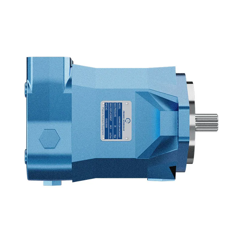
A10FM Fixed Displacement Axial Piston Motor
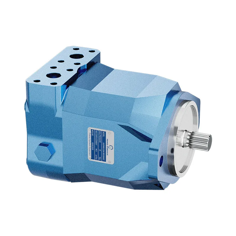
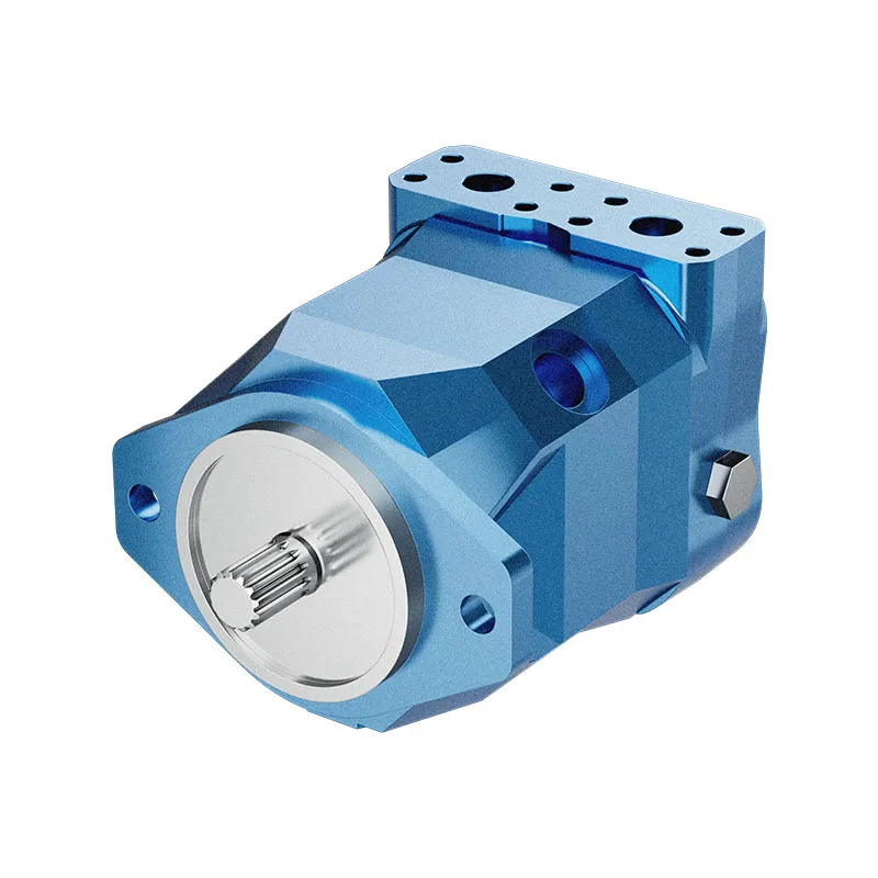
The A10FM is a fixed displacement axial piston motor. It should not be confused with the variable A10VM. The existing product information lists SAE interfaces and an optional anti-cavitation valve arrangement for fan-drive configurations.
- Fixed displacement A10 motor
- SAE mechanical and hydraulic interfaces
- Mobile and industrial applications
- Anti-cavitation valve option requires confirmation
PRANCE HYDRAULIC · PRODUCT SERIES
A10FM Fixed Displacement Axial Piston Motor
Axial piston; swashplate, fixed displacement · Confirm open or closed circuit conditions
The A10FM is a fixed displacement axial piston motor. It should not be confused with the variable A10VM. The existing product information lists SAE interfaces and an optional anti-cavitation valve arrangement for fan-drive configurations.
Modèle
✓
Demander un devisVoir les données techniques et la fiche techniqueA10FMAxial piston; swashplate, fixed displacement
Confirm the complete model and approved specification with Prance Hydraulic. Product-series references alone do not establish interchangeability.
Étude de configuration · Documentation technique · Sélection de produits
Détails du produit
- Fixed displacement A10 motor
- SAE mechanical and hydraulic interfaces
- Mobile and industrial applications
- Anti-cavitation valve option requires confirmation
CATÉGORIES : Moteur à cylindrée fixe, Moteur à pistons
A10FM Features & Application
Fixed displacement A10 motor
For a fixed displacement, flow and speed remain linked by the selected displacement. Check the actual operating point and efficiency.
SAE mechanical and hydraulic interfaces
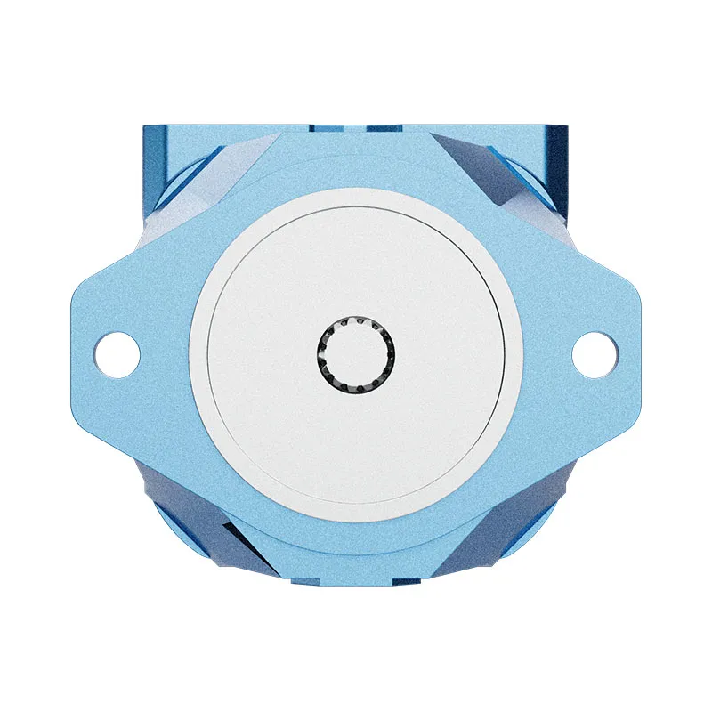
Check pilot diameter, bolt pattern, shaft engagement or port pattern against the approved installation drawing.
Mobile and industrial applications
Check the required shaft torque and speed at the same operating point. Include starting duty, return pressure and external shaft loads.
Anti-cavitation valve option requires confirmation
Specify the full MS order code, installation drawing and operating duty so the quotation can identify the proposed configuration.
A10FM Specifications
| Series / model | A10FM |
|---|---|
| Product type | A10FM Fixed Displacement Axial Piston Motor |
| Conception | Axial piston; swashplate, fixed displacement |
| Circuit / selection | Confirm open or closed circuit conditions |
| Contrôle du déplacement | Fixed; A10VM is the separate variable-motor family |
| Interface reference | SAE; confirm the selected flange, shaft and ports |
A10FM Selection & Configuration
The A10FM is a fixed displacement axial piston motor. It should not be confused with the variable A10VM. The existing product information lists SAE interfaces and an optional anti-cavitation valve arrangement for fan-drive configurations.
For a fan drive, specify acceleration, deceleration and the possibility of the fan overrunning the oil supply. Confirm replenishment and any anti-cavitation option in the ordered configuration. Electrical control elsewhere in a circuit does not make the A10FM displacement variable.
Your Application.
The Right Configuration.
Hydraulic pumps · Hydraulic motors · Hydraulic valves
Send the MS nameplate, operating requirements and installation drawing for a configuration review before quoting.
- Model review — send the full model code or an existing nameplate photograph.
- Interface matching — confirm shaft, mounting flange, rotation and ports.
- Operating conditions — provide flow, pressure, speed, fluid and duty cycle.
- Documentation — request the relevant product data and drawings for your review.

A10FM Buying Guide
Use this sequence to prepare the A10FM configuration for review and quotation.
- Define starting and continuous torque, speed range and duty cycle.
- Specify available flow, work-port pressure difference and return pressure.
- Confirm the displacement setting and required behavior during starting and stopping.
- Check shaft, mounting pilot, flange, port orientation and external loads.
- Review case drainage, replenishment and any displacement control.
- Specify fluid conditions and any independent braking requirement.
- Approve the complete model, operating envelope, drawing and quantity.
Selection, Documentation & Project Support

Selection Support
Learn more →Share your hydraulic circuit, operating point and installation requirements for a configuration discussion.
Flow · Pressure · Speed · Interfaces

Technical Resources
Learn more →Review product documentation, model codes and technical data before finalizing the specification.
Datasheets · Model codes · Drawings

cURL Too many subrequests by single Worker invocation. To configure this limit, refer to https://developers.cloudflare.com/workers/wrangler/configuration/#limits
Learn more →cURL Too many subrequests by single Worker invocation. To configure this limit, refer to https://developers.cloudflare.com/workers/wrangler/configuration/#limits.
cURL Too many subrequests by single Worker invocation. To configure this limit, refer to https://developers.cloudflare.com/workers/wrangler/configuration/#limits
Configuration, Quantity & Delivery
Confirm the complete MS code, approved drawing and operating limits. Availability, quantity, documentation and delivery date are confirmed in the quotation.
Discuss Your A10FM Application
Send the full model code, operating duty, installation details and quantity.
Request a A10FM QuotationA10FM Questions Before Ordering
What type of product is the A10FM?
A10FM Fixed Displacement Axial Piston Motor. Design: Axial piston; swashplate, fixed displacement. Confirm open or closed circuit conditions. Confirm the complete order code for the offered version.
Can a similar motor replace the A10FM?
cURL Too many subrequests by single Worker invocation. To configure this limit, refer to https://developers.cloudflare.com/workers/wrangler/configuration/#limits.
cURL Too many subrequests by single Worker invocation. To configure this limit, refer to https://developers.cloudflare.com/workers/wrangler/configuration/#limits
cURL Too many subrequests by single Worker invocation. To configure this limit, refer to https://developers.cloudflare.com/workers/wrangler/configuration/#limits.
A10FM Technical Data & Documents
View A10FM catalog data and operating conditions
cURL Too many subrequests by single Worker invocation. To configure this limit, refer to https://developers.cloudflare.com/workers/wrangler/configuration/#limits.
Données techniques
Fluids
Prior to project design, please see our technical data sheets RE 90220 (mineral oil) and RE 90221 (environmentally acceptable fluids) for detailed information on fluids and operating conditions. For operation on environmentally acceptable fluids please consult us (when ordering, please state in clear text the fluid to be used).Operating viscosity range
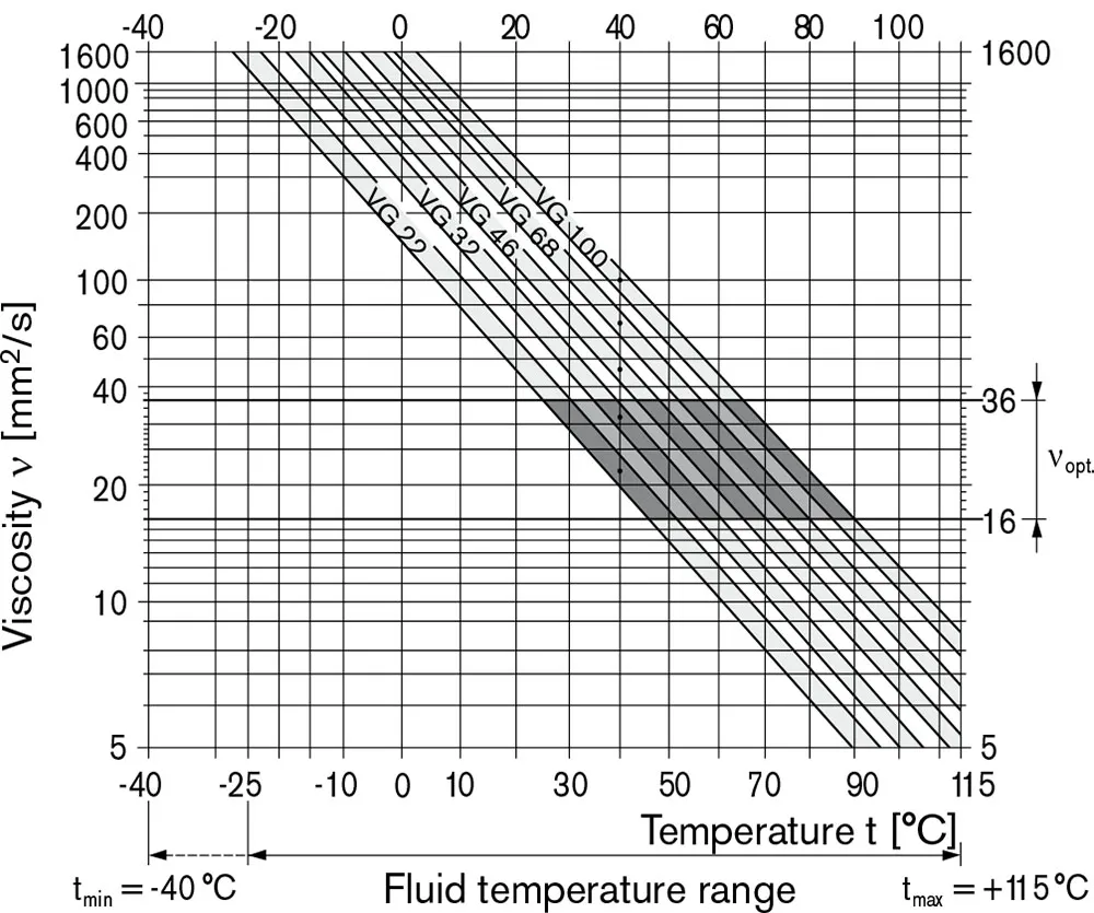
To achieve optimum values for efficiency and service life we recommend an operation viscosity (at operating temperature)within the range, νopt = opt. operating viscosity 16…36 mm2/s referred to the tank temperature (open circuit).Limit of viscosity range
For critical operation conditions the following values apply: νmincURL Too many subrequests by single Worker invocation. To configure this limit, refer to https://developers.cloudflare.com/workers/wrangler/configuration/#limits2/s (closed circuit) 10 mm2/s (open circuit) for short periods (t ≤ 1 min) at a max. perm. temperature of 115 ℃. Please note that the max. leakage fluid temperature of 115 ℃ is also not exceeded in certain areas (for instance bearing area).The fluid temperature in the bearing area is approx.5 K higher than the average leakage fluid temperature νmaxcURL Too many subrequests by single Worker invocation. To configure this limit, refer to https://developers.cloudflare.com/workers/wrangler/configuration/#limits2/s for short periods (t≤1 min) on cold start (tmin =p≤ 30 bar, n ≤ 1000 min-1At temperatures between -40℃ and -25℃ special measures are required, please consult us for further information.For detailed information on operation with low temperatures see data sheet RE 90300-03-B.Diagramme de sélection
Notes on the selection of the hydraulic fluid
In order to select the correct fluid, it is necessary to know the operating temperature in the tank (open circuit) in relation to the ambient temperature. The fluid should be selected so that within the operating temperature range, the viscosity lies within the optimum range (νopt),see shaded section of the selection diagram. We recommend to select the higher viscosity grade in each case. Example: at an ambient temperature of X℃ the operating temperature in the tank is 60℃. In the optimum viscosity range(νopt; shaded area) this corresponds to viscosity grades VG 46 resp. VG 68; VG 68 should be selected.Important :
The leakage oil (case drain oil) temperature is influenced by pressure and input speed and is always higher than the tank temperature. However, at no point of the component may the temperature exceed 115℃. If it is not possible to comply with the above conditions because of extreme operating parameters please consult us.Filtration of the hydraulic fluid
Filtration improves the cleanliness level of the hydraulic fluid,which, in turn, increases the service life of the axial piston unit. To ensure the functional reliability of the axial piston unit, a gravimetric evaluation is necessary for the hydraulic fluid to determine the amount of contamination by solid matter and to determine the cleanliness level according to ISO 4406.A cleanliness level of at least 20/18/15 to ISO 4406 is to be maintained. If above requirements cannot be maintained please consult us.Operating pressure range
Pressure at service line port (pressure port) A or B| Pression nominale Pnom | 280 bar absolute |
| Maximum pressure Pmax | 350 bar absolute |
| Single operating period | 2,5 ms |
| Total operating period | 300 h |
| Minimum pressure (high pressure side) | 10 bar2) |
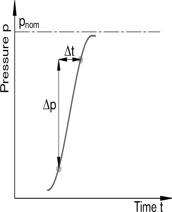
| cURL Too many subrequests by single Worker invocation. To configure this limit, refer to https://developers.cloudflare.com/workers/wrangler/configuration/#limitscURL Too many subrequests by single Worker invocation. To configure this limit, refer to https://developers.cloudflare.com/workers/wrangler/configuration/#limits | 16000 bar/s |
Pression de sortie
| à nmax | |
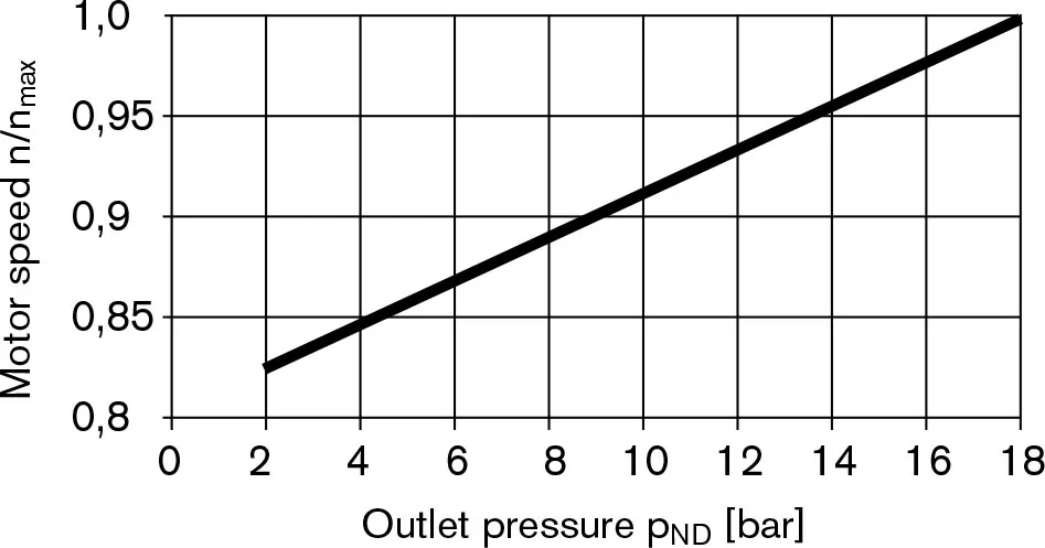
| Minimum pressure at low pressure side Pabs max | 18 bar |
Pression de drainage du carter
Maximum permissible case drain pressure (at port L, L1):| Pmax abs motor operation in open circuit | 4 bar abdos |
| Pmax abs motor operation in closed circuit | 4 bar abdos |
| Pmax abs pump/motor operation in open circuit | 2 bar abdos |
Sens de circulation
| viewed on drive shaft | |||||
| clockwise rotation | counter clockwise rotation | ||||
| A to B | B to A | ||||
Definitions
Pression nominale Pnom The nominal pressure corresponds to the maximum design pressure. Maximum pressure Pmax The maximum pressure corresponds the maximum operating pressure within the single operating period. The sum of the single operating period must not exceed the total operating period. Minimum pressure (high-pressure side) cURL Too many subrequests by single Worker invocation. To configure this limit, refer to https://developers.cloudflare.com/workers/wrangler/configuration/#limits. cURL Too many subrequests by single Worker invocation. To configure this limit, refer to https://developers.cloudflare.com/workers/wrangler/configuration/#limitsA cURL Too many subrequests by single Worker invocation. To configure this limit, refer to https://developers.cloudflare.com/workers/wrangler/configuration/#limits.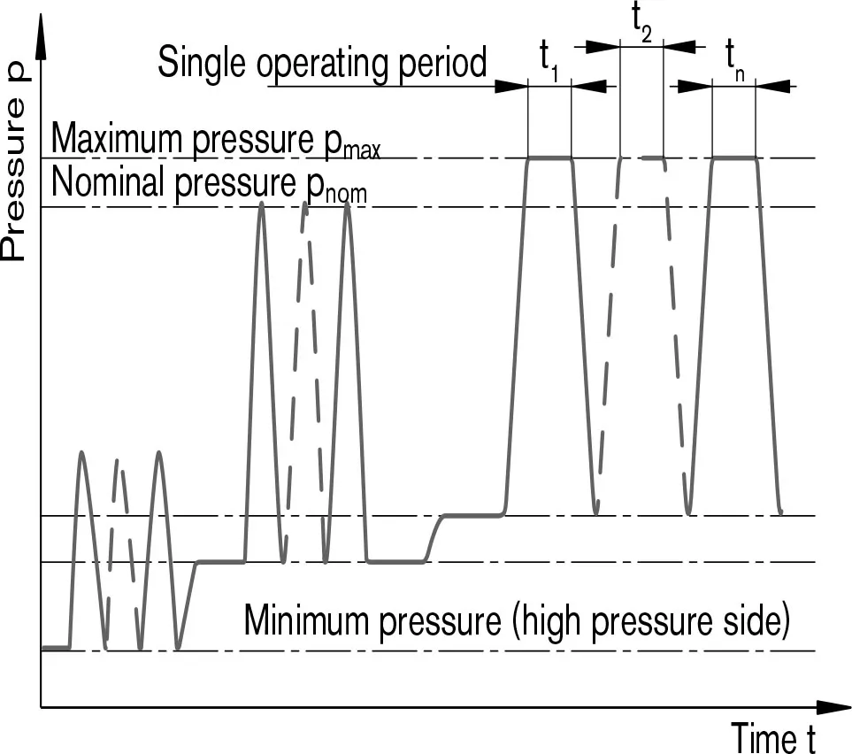 cURL Too many subrequests by single Worker invocation. To configure this limit, refer to https://developers.cloudflare.com/workers/wrangler/configuration/#limits1 cURL Too many subrequests by single Worker invocation. To configure this limit, refer to https://developers.cloudflare.com/workers/wrangler/configuration/#limits2 +… + tn
1)cURL Too many subrequests by single Worker invocation. To configure this limit, refer to https://developers.cloudflare.com/workers/wrangler/configuration/#limits
2)Lower pressures time dependent, please consult us.
Tableau des valeurs (theoretical values, without efficiency and tolerances: value rounded)
| Taille | NG | 010 | 011 | 014 | 016 | 018 | 023 | ||
| Déplacement | VGiga | cm3 | 10.6 | 11.5 | 14.1 | 16.1 | 18 | 23.5 | |
| Vitesse1) | 5000 | 4200 | 4200 | 4200 | 4200 | 4900 | |||
| à VGiga | nnom | tours par minute | |||||||
| Input flow | 53 | 48 | 59 | 68 | 76 | 115 | |||
| à nnom | qv max | L/min | |||||||
| Puissance | 24.7 | 22.5 | 27.6 | 31.6 | 35.3 | 53.6 | |||
| à nnom, Δp= 280 bar | P max | kW | |||||||
| Actual starting torque | 37.5 | 30 | 45 | 53 | 67.5 | 75 | |||
| at n= 0 rpm, Δp = 280 bar | Rien | ||||||||
| Couple | 47 | 51 | 63 | 72 | 80 | 105 | |||
| à VGiga | Δp = 280 bar | Tmax | Rien | ||||||
| Rigidité en torsion | R | c | Nm/rad | - | - | - | - | 14835 | 28478 |
| Arbre de transmission | W | c | Nm/rad | - | - | - | - | - | - |
| C | c | Nm/rad | 15084 | 18662 | 18662 | 18662 | 18662 | 30017 | |
| Moment d'inertie du groupe rotatif | JTW | kgm2 | 0.0006 | 0.00093 | 0.00093 | 0.00093 | 0.00093 | 0.0017 | |
| Accélération angulaire maximale | α | rad/s2 | 8000 | 6800 | 6800 | 6800 | 6800 | 5500 | |
| Volume du boîtier | V | L | 0.1 | 0.15 | 0.15 | 0.15 | 0.15 | 0.6 | |
| Poids approx. | m | kg | 5 | 6.5 | 6.5 | 6.5 | 6.5 | 12 | |
| Taille | NG | 028 | 037 | 045 | 058 | 063 | ||
| Déplacement | VGiga | cm3 | 28.5 | 11.5 | 14.1 | 16.1 | 18 | |
| Vitesse1) | ||||||||
| à VGiga | nnom | tours par minute | 4700 | 4200 | 4000 | 3600 | 3400 | |
| Input flow | 134 | 154 | 178 | 209 | 215 | |||
| à nnom | qv max | L/min | ||||||
| Puissance | 62.5 | 71.8 | 83.1 | 97.4 | 100.1 | |||
| à nnom, Δp= 280 bar | P max | kW | ||||||
| Actual starting torque | 105 | 125 | 170 | 205 | 230 | |||
| at n= 0 min-1, Δp = 280 bar | Rien | |||||||
| Couple | 127 | 163 | 198 | 258 | 281 | |||
| à VGiga | Δp = 280 bar | Tmax | Rien | |||||
| Rigidité en torsion | R | c | Nm/rad | 28478 | 46859 | 46859 | 80590 | 80590 |
| Arbre de transmission | W | c | Nm/rad | - | 38489 | 38489 | 60907 | 60907 |
| C | c | Nm/rad | 30017 | 46546 | 46546 | 87667 | 87667 | |
| Moment d'inertie du groupe rotatif | JTW | kgm2 | 0.0017 | 0.0033 | 0.0033 | 0.0056 | 0.0056 | |
| Accélération angulaire maximale | α | rad/s2 | 5500 | 4000 | 4000 | 3300 | 3300 | |
| Volume du boîtier | V | L | 0.6 | 0.7 | 0.7 | 0.8 | 0.8 | |
| Poids approx. | m | kg | 12 | 17 | 17 | 22 | 22 | |
Remarque
Operation above the maximum values or below the minimum values may result in a loss of function, a reduced service life or in the destruction of the axial piston unit. We recommend testing the loads by means of experiment or calculation/simulation and comparison with the permissible values.Permissible motor speed in relation to outlet pressure
Determination of motor size (NG)
| Input flow | qv=(VgcURL Too many subrequests by single Worker invocation. To configure this limit, refer to https://developers.cloudflare.com/workers/wrangler/configuration/#limitsv) | [L/min] | Vg=Displacement per revolution in cm3 Δp=Differential pressure in bar n=speed in rpm ηv=Volumetric efficiency ηhm=Mechanical-hydraulic efficiency ηt=Overall efficiency (ηt = ηv ∙ηhmcURL Too many subrequests by single Worker invocation. To configure this limit, refer to https://developers.cloudflare.com/workers/wrangler/configuration/#limitsK=Torque constant |
| Couple | T=(1,59∙Vg∙ Δp∙ηhm)/100 | [Nm] | |
| ou | T=Tk∙ Δp∙ηhm | ||
| Puissance | P=(2π∙T∙n)/60000=(qv∙Δp∙ηt)/600 | [kW] | |
| Vitesse de sortie | n=(qv∙1000∙ηv)/Vg | [rpm] | |
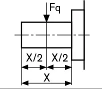
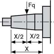
Forces radiales et axiales admissibles sur l'arbre d'entraînement
| Max. radial force at X/2 | Drive shaft R; W | Drive shaft C | Fq max | N | 250 | 350 | 350 | 350 | 350 | 1200 |
 |
 |
|||||||||
| Force axiale maximale | 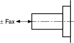 |
± Fax max | N | 400 | 700 | 700 | 700 | 700 | 1000 |
| Taille | NG | 28 | 37 | 45 | 58 | 63 | |||
| Max. radial force at X/2 | Drive shaft R; W | Drive shaft C | Fq max | N | 1200 | 1500 | 1500 | 1700 | 1700 |
|
|
||||||||
| Force axiale maximale | |
± Fax max | N | 1000 | 1500 | 1500 | 2000 | 2000 | |
cURL Too many subrequests by single Worker invocation. To configure this limit, refer to https://developers.cloudflare.com/workers/wrangler/configuration/#limits
Related Selection Resources
Request a A10FM Quotation
Tell us your required configuration, quantity and application.
Produits associés
Compare related hydraulic motors and confirm the complete configuration for your application.

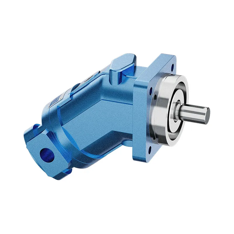

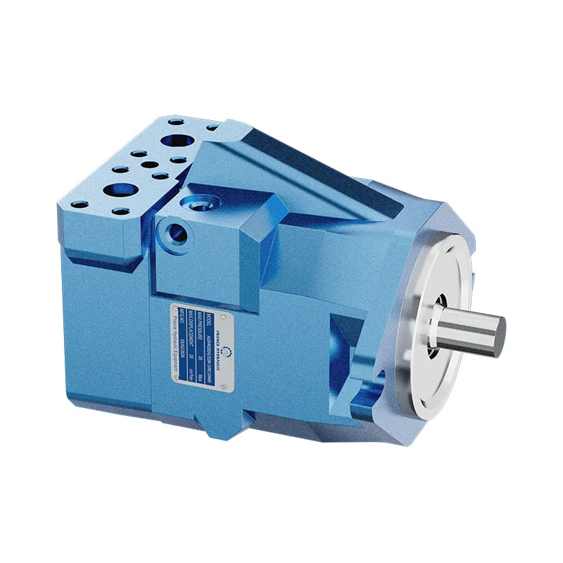
Ordering code for standard program
| A10F | M | / | 52 | - | V | C | ||||||
| 01 | 02 | 03 | 04 | 05 | 06 | 07 | 08 | 09 | 10 | 11 |
Unité à pistons axiaux
| 01 | Swashplate design, fixed displacement, nominal pressure 280 bar, maximum pressure 350 bar | A10F |
Mode de fonctionnement
| 02 | Motor, open and closed circuit | M |
Taille (NG)
| 03 | Theoretical displacement | 018 | 023 | 028 | 037 | 045 | 058 | 063 |
Séries
| 04 | Series 5, Index 2 | 52 |
Sens de rotation
| 05 | Vu sur l'arbre de transmission | dans le sens des aiguilles d'une montre | R1) |
| counter clockwise | L1) | ||
| bidirectional | W |
Joints d'étanchéité
| 06 | FKM (Fluoro-rubber) | V |
Arbre de transmission
| 018 | 023 | 028 | 037 | 045 | 058 | 063 | |||||
| 07 | Splined shaft to ISO 3019-1 (SAE J744) | ○ | ● | ● | ● | ● | ● | ● | R | ||
| Splined shaft to ISO 3019-1 (SAE J744) | – | ○ | ○ | ● | ● | ● | ● | W | |||
| Tapered with woodruff key and threaded end | ○ | ● | ● | ● | ● | ● | ● | C | |||
Bride de fixation
| 018 | 023 | 028 | 037 | 045 | 058 | 063 | |||
| 08 | SAE à 2 trous | ○ | ● | ● | ● | ● | ● | ● | C |
Ports pour lignes de service
| 018 | 023 | 028 | 037 | 045 | 058 | 063 | |||
| 09 | SAE-flange ports A and B on side, same side Mounting bolts metric | - | ● | ● | ● | ● | ● | ● | 10N00 |
| Threaded ports A and B,metric, on side, same side | ○ | ● | ● | ● | ● | ● | ● | 16N00 | |
Ventile
| 018 | 023 | 028 | 037 | 045 | 058 | 063 | |||
| 10 | Without valves | ○ | ● | ● | ● | ● | ● | ● | 0 |
| With integrated flushing valve | - | ● | ● | ● | ● | ● | ● | 7 | |
| With integrated anti cavitation valve | ○ | ● | ● | ● | ● | ● | ● | 2 | |
Capteur de vitesse
| 018 | 023 | 028 | 037 | 045 | 058 | 063 | |||
| 11 | Sans capteur de vitesse | ○ | ● | ● | ● | ● | ● | ● | |
| Prepared for speed sensor (for inductive speed sensor ID) | ○ | ● | ● | ● | ● | ○ | ○ | D | |
•=available ○=on request — =not available
1)Only necessary in conjunction with valve configuration "2" (integrated anti cavitation valve)
| A10F | E | / | 52 | - | V | |||||||
| 01 | 02 | 03 | 04 | 05 | 06 | 07 | 08 | 09 | 10 | 11 |
Unité à pistons axiaux
| 01 | Swashplate design, fixed displacement, nominal pressure 280 bar, maximum pressure 350 bar | A10F |
Mode de fonctionnement
| 02 | Motor, open and closed circuit | E |
Taille (NG)
| 03 | Theoretical displacement | 010 | 011 | 014 | 016 | 018 | 023 | 028 | 037 | 045 | 058 | 063 |
Séries
| 04 | Series 5, Index 2 | 52 |
Sens de rotation
| 05 | Vu sur l'arbre de transmission | dans le sens des aiguilles d'une montre | R1) |
| counter clockwise | L1) | ||
| bidirectional | W |
Joints d'étanchéité
| 06 | FKM (Fluoro-rubber) | V |
Arbre de transmission
| 010 | 011 | 014 | 016 | 018 | 023 | 028 | 037 | 045 | 058 | 063 | |||||
| 07 | Splined shaft to ISO 3019-1 (SAE J744) | ○ | ● | ● | ● | ● | ● | ● | ● | ● | ● | ● | R | ||
| Splined shaft to ISO 3019-1 (SAE J744) | – | – | – | – | – | ● | ● | ● | ● | ● | ● | W | |||
| Tapered with woodruff key and threaded end | ● | ● | ● | ● | ● | ● | ● | ● | ● | ● | ● | C | |||
Bride de fixation
| 010 | 011 | 014 | 016 | 018 | 023 | 028 | 037 | 045 | 058 | 063 | |||
| 08 | SAE à 2 trous | ● | ● | ● | ● | ● | - | - | - | - | - | - | C2) |
| Special 2-hole | - | - | - | - | - | ● | ● | ● | ● | ● | ● | F | |
| Special 8-hole | - | ● | ● | ● | ● | - | - | - | - | - | - | H | |
Ports pour lignes de service
| 010 | 011 | 014 | 016 | 018 | 023 | 028 | 037 | 045 | 058 | 063 | |||
| 09 | SAE-flange ports A and B, on side, same side mounting bolts metric | - | - | - | - | - | ● | ● | ● | ● | ● | ● | 10N00 |
| Threaded ports A and B,metric, on side, same side | ● | ● | ● | ● | ● | ● | ● | ● | ● | ● | ● | 16N00 | |
Ventile
| 010 | 011 | 014 | 016 | 018 | 023 | 028 | 037 | 045 | 058 | 063 | |||
| 10 | Without valves | ○ | ● | ○ | ● | ● | ● | ● | ● | ● | ● | ● | 0 |
| With integrated flushing valve | - | - | - | - | - | ● | ● | ● | ● | ● | ● | 7 | |
| With integrated anti cavitation valve | ● | ● | ● | ● | ● | ● | ● | ● | ● | ● | ● | 2 | |
Capteur de vitesse
| 010 | 011 | 014 | 016 | 018 | 023 | 028 | 037 | 045 | 058 | 063 | |||
| 11 | Sans capteur de vitesse | ● | ● | ● | ● | ● | ● | ● | ● | ● | ● | ● | |
| Prepared for speed sensor (for inductive speed sensor ID) | – | – | – | – | ○ | ● | ● | ● | ● | ○ | ○ | D | |
•=available ○=on request — =not available
1)Only necessary in conjunction with valve configuration "2" (integrated anti cavitation valve)
2)R-shaft with C-flange on sizes 10 to 18 in preparation
Données techniques
Fluids
Prior to project design, please see our technical data sheets RE 90220 (mineral oil) and RE 90221 (environmentally acceptable fluids) for detailed information on fluids and operating conditions.
For operation on environmentally acceptable fluids please consult us (when ordering, please state in clear text the fluid to be used).
Operating viscosity range
To achieve optimum values for efficiency and service life we recommend an operation viscosity (at operating temperature)within the range,
νopt = opt. operating viscosity 16...36 mm2/s
referred to the tank temperature (open circuit).
Limit of viscosity range
cURL Too many subrequests by single Worker invocation. To configure this limit, refer to https://developers.cloudflare.com/workers/wrangler/configuration/#limits
νmincURL Too many subrequests by single Worker invocation. To configure this limit, refer to https://developers.cloudflare.com/workers/wrangler/configuration/#limits2cURL Too many subrequests by single Worker invocation. To configure this limit, refer to https://developers.cloudflare.com/workers/wrangler/configuration/#limits
cURL Too many subrequests by single Worker invocation. To configure this limit, refer to https://developers.cloudflare.com/workers/wrangler/configuration/#limits2cURL Too many subrequests by single Worker invocation. To configure this limit, refer to https://developers.cloudflare.com/workers/wrangler/configuration/#limits
cURL Too many subrequests by single Worker invocation. To configure this limit, refer to https://developers.cloudflare.com/workers/wrangler/configuration/#limits
cURL Too many subrequests by single Worker invocation. To configure this limit, refer to https://developers.cloudflare.com/workers/wrangler/configuration/#limits.
cURL Too many subrequests by single Worker invocation. To configure this limit, refer to https://developers.cloudflare.com/workers/wrangler/configuration/#limits
νmaxcURL Too many subrequests by single Worker invocation. To configure this limit, refer to https://developers.cloudflare.com/workers/wrangler/configuration/#limits2/s
for short periods (t≤1 min)
on cold start
(tmin =p≤ 30 bar, n ≤ 1000 min-1,-25 °C).
At temperatures between -40℃ and -25℃ special measures are required, please consult us for further information.For detailed information on operation with low temperatures see data sheet RE 90300-03-B.
Diagramme de sélection
Notes on the selection of the hydraulic fluid
In order to select the correct fluid, it is necessary to know the operating temperature in the tank (open circuit) in relation to the ambient temperature.
The fluid should be selected so that within the operating temperature range, the viscosity lies within the optimum range (νopt),see shaded section of the selection diagram. We recommend to select the higher viscosity grade in each case.
Example: at an ambient temperature of X℃ the operating temperature in the tank is 60℃. In the optimum viscosity range(νopt; shaded area) this corresponds to viscosity grades VG 46 resp. VG 68; VG 68 should be selected.
Important :
The leakage oil (case drain oil) temperature is influenced by pressure and input speed and is always higher than the tank temperature. However, at no point of the component may the temperature exceed 115℃.
If it is not possible to comply with the above conditions because of extreme operating parameters please consult us.
Filtration of the hydraulic fluid
Filtration improves the cleanliness level of the hydraulic fluid,which, in turn, increases the service life of the axial piston unit.
To ensure the functional reliability of the axial piston unit, a gravimetric evaluation is necessary for the hydraulic fluid to determine the amount of contamination by solid matter and to determine the cleanliness level according to ISO 4406.A cleanliness level of at least 20/18/15 to ISO 4406 is to be maintained.
If above requirements cannot be maintained please consult us.
Operating pressure range
Pressure at service line port (pressure port) A or B
| Pression nominale Pnom | 280 bar absolute |
| Maximum pressure Pmax | 350 bar absolute |
| Single operating period | 2,5 ms |
| Total operating period | 300 h |
| Minimum pressure (high pressure side) | 10 bar2) |
| cURL Too many subrequests by single Worker invocation. To configure this limit, refer to https://developers.cloudflare.com/workers/wrangler/configuration/#limitscURL Too many subrequests by single Worker invocation. To configure this limit, refer to https://developers.cloudflare.com/workers/wrangler/configuration/#limits | 16000 bar/s |
Pression de sortie
| à nmax | |
| Minimum pressure at low pressure side Pabs max | 18 bar |
Pression de drainage du carter
Maximum permissible case drain pressure
(at port L, L1):
| Pmax abs motor operation in open circuit | 4 bar abdos |
| Pmax abs motor operation in closed circuit | 4 bar abdos |
| Pmax abs pump/motor operation in open circuit | 2 bar abdos |
Sens de circulation
| viewed on drive shaft | |||||
| clockwise rotation | counter clockwise rotation | ||||
| A to B | B to A | ||||
Definitions
Pression nominale Pnom
cURL Too many subrequests by single Worker invocation. To configure this limit, refer to https://developers.cloudflare.com/workers/wrangler/configuration/#limits
cURL Too many subrequests by single Worker invocation. To configure this limit, refer to https://developers.cloudflare.com/workers/wrangler/configuration/#limits.
Maximum pressure Pmax
The maximum pressure corresponds the maximum operating pressure within the single operating period. The sum of the single operating period must not exceed the total operating period.
Minimum pressure (high-pressure side)
cURL Too many subrequests by single Worker invocation. To configure this limit, refer to https://developers.cloudflare.com/workers/wrangler/configuration/#limits.
cURL Too many subrequests by single Worker invocation. To configure this limit, refer to https://developers.cloudflare.com/workers/wrangler/configuration/#limitsA
cURL Too many subrequests by single Worker invocation. To configure this limit, refer to https://developers.cloudflare.com/workers/wrangler/configuration/#limits.
cURL Too many subrequests by single Worker invocation. To configure this limit, refer to https://developers.cloudflare.com/workers/wrangler/configuration/#limits1 cURL Too many subrequests by single Worker invocation. To configure this limit, refer to https://developers.cloudflare.com/workers/wrangler/configuration/#limits2 cURL Too many subrequests by single Worker invocation. To configure this limit, refer to https://developers.cloudflare.com/workers/wrangler/configuration/#limitsn
1)cURL Too many subrequests by single Worker invocation. To configure this limit, refer to https://developers.cloudflare.com/workers/wrangler/configuration/#limits
2)Lower pressures time dependent, please consult us.
Tableau des valeurs (theoretical values, without efficiency and tolerances: value rounded)
| Taille | NG | 010 | 011 | 014 | 016 | 018 | 023 | ||
| Déplacement | VGiga | cm3 | 10.6 | 11.5 | 14.1 | 16.1 | 18 | 23.5 | |
| Vitesse1) | 5000 | 4200 | 4200 | 4200 | 4200 | 4900 | |||
| à VGiga | nnom | tours par minute | |||||||
| Input flow | 53 | 48 | 59 | 68 | 76 | 115 | |||
| à nnom | qv max | L/min | |||||||
| Puissance | 24.7 | 22.5 | 27.6 | 31.6 | 35.3 | 53.6 | |||
| à nnom, Δp= 280 bar | P max | kW | |||||||
| Actual starting torque | 37.5 | 30 | 45 | 53 | 67.5 | 75 | |||
| at n= 0 rpm, Δp = 280 bar | Rien | ||||||||
| Couple | 47 | 51 | 63 | 72 | 80 | 105 | |||
| à VGiga | Δp = 280 bar | Tmax | Rien | ||||||
| Rigidité en torsion | R | c | Nm/rad | - | - | - | - | 14835 | 28478 |
| Arbre de transmission | W | c | Nm/rad | - | - | - | - | - | - |
| C | c | Nm/rad | 15084 | 18662 | 18662 | 18662 | 18662 | 30017 | |
| Moment d'inertie du groupe rotatif | JTW | kgm2 | 0.0006 | 0.00093 | 0.00093 | 0.00093 | 0.00093 | 0.0017 | |
| Accélération angulaire maximale | α | rad/s2 | 8000 | 6800 | 6800 | 6800 | 6800 | 5500 | |
| Volume du boîtier | V | L | 0.1 | 0.15 | 0.15 | 0.15 | 0.15 | 0.6 | |
| Poids approx. | m | kg | 5 | 6.5 | 6.5 | 6.5 | 6.5 | 12 | |
| Taille | NG | 028 | 037 | 045 | 058 | 063 | ||
| Déplacement | VGiga | cm3 | 28.5 | 11.5 | 14.1 | 16.1 | 18 | |
| Vitesse1) | ||||||||
| à VGiga | nnom | tours par minute | 4700 | 4200 | 4000 | 3600 | 3400 | |
| Input flow | 134 | 154 | 178 | 209 | 215 | |||
| à nnom | qv max | L/min | ||||||
| Puissance | 62.5 | 71.8 | 83.1 | 97.4 | 100.1 | |||
| à nnom, Δp= 280 bar | P max | kW | ||||||
| Actual starting torque | 105 | 125 | 170 | 205 | 230 | |||
| at n= 0 min-1, Δp = 280 bar | Rien | |||||||
| Couple | 127 | 163 | 198 | 258 | 281 | |||
| à VGiga | Δp = 280 bar | Tmax | Rien | |||||
| Rigidité en torsion | R | c | Nm/rad | 28478 | 46859 | 46859 | 80590 | 80590 |
| Arbre de transmission | W | c | Nm/rad | - | 38489 | 38489 | 60907 | 60907 |
| C | c | Nm/rad | 30017 | 46546 | 46546 | 87667 | 87667 | |
| Moment d'inertie du groupe rotatif | JTW | kgm2 | 0.0017 | 0.0033 | 0.0033 | 0.0056 | 0.0056 | |
| Accélération angulaire maximale | α | rad/s2 | 5500 | 4000 | 4000 | 3300 | 3300 | |
| Volume du boîtier | V | L | 0.6 | 0.7 | 0.7 | 0.8 | 0.8 | |
| Poids approx. | m | kg | 12 | 17 | 17 | 22 | 22 | |
1)for maximum speed an outlet pressure (in low pressure side) of 18 bar is required
Remarque
Operation above the maximum values or below the minimum values may result in a loss of function, a reduced service life or in the destruction of the axial piston unit. We recommend testing the loads by means of experiment or calculation/simulation and comparison with the permissible values.
Permissible motor speed in relation to outlet pressure
Determination of motor size (NG)
| Input flow | qv=(VgcURL Too many subrequests by single Worker invocation. To configure this limit, refer to https://developers.cloudflare.com/workers/wrangler/configuration/#limitsv) | [L/min] | Vg=Displacement per revolution in cm3 Δp=Differential pressure in bar n=speed in rpm ηv=Rendement volumétrique ηhm=Efficacité mécanique-hydraulique ηt=Overall efficiency (ηt = ηv ∙ηhm) TK=Torque constant |
| Couple | T=(1,59∙Vg∙ Δp∙ηhm)/100 | [Nm] | |
| ou | T=Tk∙ Δp∙ηhm | ||
| Puissance | P=(2π∙T∙n)/60000=(qv∙Δp∙ηt)/600 | [kW] | |
| Vitesse de sortie | n=(qv∙1000∙ηv)/Vg | [rpm] | |
Forces radiales et axiales admissibles sur l'arbre d'entraînement
| Max. radial force at X/2 | Drive shaft R; W | Drive shaft C | Fq max | N | 250 | 350 | 350 | 350 | 350 | 1200 |
|
|
|||||||||
| Force axiale maximale | |
± Fax max | N | 400 | 700 | 700 | 700 | 700 | 1000 |
| Taille | NG | 28 | 37 | 45 | 58 | 63 | |||
| Max. radial force at X/2 | Drive shaft R; W | Drive shaft C | Fq max | N | 1200 | 1500 | 1500 | 1700 | 1700 |
|
|
||||||||
| Force axiale maximale | |
± Fax max | N | 1000 | 1500 | 1500 | 2000 | 2000 | |
