Wenzhou Prance Hydraulic Equipment Co., Ltd.

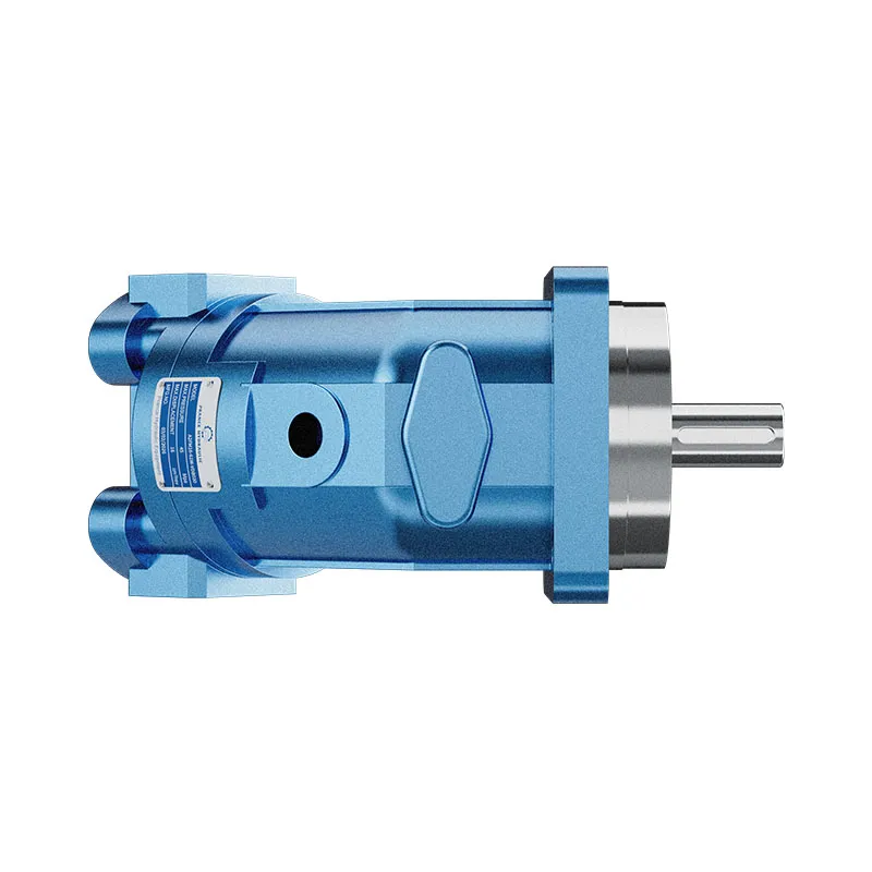


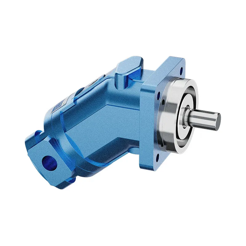
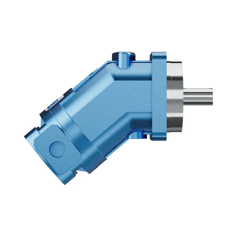
A2FM Fixed Displacement Bent Axis Motor
The A2FM fixed displacement motor converts hydraulic flow and pressure difference into shaft speed and torque. It is listed for open and closed circuits, provided the selected model meets the circuit pressure, drainage and installation conditions.
- Fixed displacement motor
- Bent-axis piston design
- Mobile and industrial applications
- Size and interfaces selected from the model code
PRANCE HYDRAULIC · PRODUCT SERIES
A2FM Fixed Displacement Bent Axis Motor
Axial piston; bent axis, fixed displacement · Open and closed circuits, subject to configuration
The A2FM fixed displacement motor converts hydraulic flow and pressure difference into shaft speed and torque. It is listed for open and closed circuits, provided the selected model meets the circuit pressure, drainage and installation conditions.
Model
✓
Request a QuotationVer Datos Técnicos y Ficha TécnicaA2FMAxial piston; bent axis, fixed displacement
Confirm the complete model and approved specification with Prance Hydraulic. Product-series references alone do not establish interchangeability.
Configuration review · Technical documentation · Product selection
Detalles del producto
- Fixed displacement motor
- Bent-axis piston design
- Mobile and industrial applications
- Size and interfaces selected from the model code
CATEGORIES: Motor de desplazamiento fijo, Motor de pistón
A2FM Features & Application
Fixed displacement motor
For a fixed displacement, flow and speed remain linked by the selected displacement. Check the actual operating point and efficiency.
Bent-axis piston design
Specify the full MS order code, installation drawing and operating duty so the quotation can identify the proposed configuration.
Mobile and industrial applications
Check the required shaft torque and speed at the same operating point. Include starting duty, return pressure and external shaft loads.
Size and interfaces selected from the model code
Check pilot diameter, bolt pattern, shaft engagement or port pattern against the approved installation drawing.
A2FM Specifications
| Series / model | A2FM |
|---|---|
| Product type | A2FM Fixed Displacement Bent Axis Motor |
| Diseño | Axial piston; bent axis, fixed displacement |
| Circuit / selection | Open and closed circuits, subject to configuration |
| Control de desplazamiento | Fixed |
| Fluido hidráulico | Mineral-oil use described; confirm other fluids and seal options individually |
A2FM Selection & Configuration
The A2FM fixed displacement motor converts hydraulic flow and pressure difference into shaft speed and torque. It is listed for open and closed circuits, provided the selected model meets the circuit pressure, drainage and installation conditions.
Choose displacement from the required torque-speed duty and available flow, then check external shaft loads and case pressure. Increasing supply pressure alone does not establish safe operation if the return or drain is restricted. Use the selected model data for continuous and peak conditions.
cURL Too many subrequests by single Worker invocation. To configure this limit, refer to https://developers.cloudflare.com/workers/wrangler/configuration/#limits.
cURL Too many subrequests by single Worker invocation. To configure this limit, refer to https://developers.cloudflare.com/workers/wrangler/configuration/#limits.
Hydraulic pumps · Hydraulic motors · Hydraulic valves
Send the MS nameplate, operating requirements and installation drawing for a configuration review before quoting.
- Model review — send the full model code or an existing nameplate photograph.
- Interface matching — confirm shaft, mounting flange, rotation and ports.
- Operating conditions — provide flow, pressure, speed, fluid and duty cycle.
- Documentation — request the relevant product data and drawings for your review.

A2FM Buying Guide
Use this sequence to prepare the A2FM configuration for review and quotation.
- Define starting and continuous torque, speed range and duty cycle.
- Specify available flow, work-port pressure difference and return pressure.
- Confirm the displacement setting and required behavior during starting and stopping.
- Check shaft, mounting pilot, flange, port orientation and external loads.
- Review case drainage, replenishment and any displacement control.
- Specify fluid conditions and any independent braking requirement.
- Approve the complete model, operating envelope, drawing and quantity.

Selection, Documentation & Project Support

Selection Support
Learn more →Share your hydraulic circuit, operating point and installation requirements for a configuration discussion.
Flow · Pressure · Speed · Interfaces

Technical Resources
Learn more →Review product documentation, model codes and technical data before finalizing the specification.
Datasheets · Model codes · Drawings

Project Inquiries
Learn more →Send your required model, quantity, application and project requirements to discuss your inquiry.
Product inquiries · Configuration review
Configuration, Quantity & Delivery
Confirm the complete MS code, approved drawing and operating limits. Availability, quantity, documentation and delivery date are confirmed in the quotation.
Discuss Your A2FM Application
Send the full model code, operating duty, installation details and quantity.
Request a A2FM QuotationA2FM Questions Before Ordering
What type of product is the A2FM?
AA2FM Fixed Displacement Bent Axis Motor. Design: Axial piston; bent axis, fixed displacement. Open and closed circuits, subject to configuration. Confirm the complete order code for the offered version.
Can a similar motor replace the A2FM?
cURL Too many subrequests by single Worker invocation. To configure this limit, refer to https://developers.cloudflare.com/workers/wrangler/configuration/#limits.
cURL Too many subrequests by single Worker invocation. To configure this limit, refer to https://developers.cloudflare.com/workers/wrangler/configuration/#limits
cURL Too many subrequests by single Worker invocation. To configure this limit, refer to https://developers.cloudflare.com/workers/wrangler/configuration/#limits.
A2FM Technical Data & Documents
View A2FM catalog data and operating conditions
cURL Too many subrequests by single Worker invocation. To configure this limit, refer to https://developers.cloudflare.com/workers/wrangler/configuration/#limits.
Datos técnicos
Fluido hidráulico
El motor de desplazamiento fijo A2FM es adecuado para su uso con aceite mineral.Rango de viscosidad
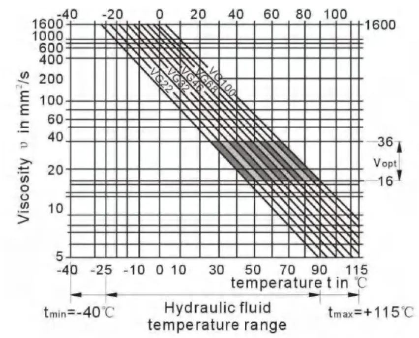
We recommend that a viscosity (at operating temperature)for optimum efficiency and service life purposes of Vopt= optimum viscosity 16…36mm2Se elegirá teniendo en cuenta la temperatura de circulación (circuito cerrado) y la temperatura del depósito (circuito abierto).Límites del rango de viscosidad
The following values apply extreme cases: Vmín=5mm2/s short term(t < 3 min) at max. permitted temperature tmáx=115℃ Vmáx= 1600 mm2/s short term (t<3 min) with cold start(P<3MPa, n≤1000rpm tmínTenga en cuenta que tampoco debe superarse localmente la temperatura máxima del fluido hidráulico (p. ej., en la zona de los cojinetes). La temperatura en la zona de los cojinetes es —en función de la presión y la velocidad— hasta 12 K superior a la temperatura media de drenaje de la carcasa.Diagrama de selección
Detalles sobre la elección de fluido hidráulico
The correct choice of pressure fluid requires knowledge of the operating temperature in relation to the ambient temperature:in a closed circuit the circulation temperature,in an open circuit the tank temperature. The hydraulic fluid should be selected so that within the operating temperature range,the operating viscosity lies within the optimum range (υ opt) (see shaded section of the selection diagram).We recommend that the highest possible viscosity range should be chosen in each case. Example:At an ambient temperature of X℃ an operating temperature of 60℃ is set in the circuit . In the optimum operating viscosity range (υ opt; shaded area) this corresponds to the viscosity classes VG 46 or VG68; to be selected: CG 68 Please note : The leakage fluid temperature, which is affected by pressure and rotational speed, is always higher than the circulation temperature or tank temperature. At no point in the system may t-he temperature be higher than 115℃.Filtración
The finer the filtration, the cleaner the fluid and the longer the service life of the axial piston unit. To ensure proper function of the axial piston unit, the hydraulic fluid must have a cleanliness level of least. 20/18/15 according to ISO 4406. At very high hydraulic fluid temperatures (90℃ to max. 115℃),a cleanliness level of at least. 19/17/14 according to ISO 4406 is required. Please contact us if these cleanliness levels cannot be achieved. Rango de presión de operación Maximum pressure on port A or B (pressure data according to DIN 24312)| Extremo del eje A,Z | Extremo del eje B, P | |
| Presión nominal PN | 40 MPa | 35 MPa |
| Presión máxima Pmáx | 45 MPa | 40 MPa |
| presión de suma (A+B) | 70 MPa | 70 MPa |
Dirección del flujo
Rango de velocidad
Sin límite de velocidad mínima nmín. Si se requiere un movimiento uniforme,mín no debe ser inferior a 50 rpm.Anillo de sello de eje
permissible pressure load The pressure service life of the shaft seal ring is affected by the speed of the motor and the case drain pressure. The permitted loading with intermittent case drain pressure depends on the rotational speed(see chart). Short-term (t<5 min) pressure spikes of up to 1 Mpa absolute are permitted. The average permanent case drain pressure must not exceed 0. 3Mpa absolute. The pressure in the case must be equal to or greater than the external pressure on the shaft seal.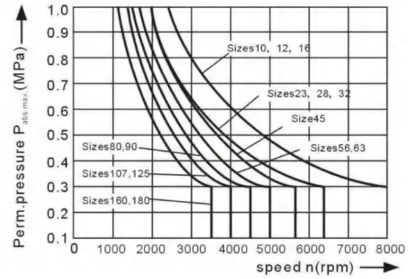
Rango de temperatura
The FKM shaft seal is admissible for a housing temperature range from -25℃ to +115℃Tatabla de valores (valores teóricos, ignorando ηmín y ηv; valores redondeados
| Tamaño | 10 | 12 | 16 | 23 | 28 | 32 | 45 | |||
| Desplazamiento | Vg | mL/r | 10.3 | 12.0 | 16.0 | 22.9 | 28.1 | 32 | 45.6 | |
| Velocidad máxima | nmáx | mín-1 | 8000 | 8000 | 8000 | 6300 | 6300 | 6300 | 5600 | |
| nlímite máximo1) | mín-1 | 8800 | 8800 | 8800 | 6900 | 6900 | 6900 | 6200 | ||
| Caudal máx. | qvmax | L/min | 82 | 96 | 128 | 144 | 176 | 201 | 255 | |
| Constantes de par | TK | Nm/MPa | 1.64 | 1.9 | 2.5 | 3.6 | 4.45 | 5.09 | 7.25 | |
| Par en | Δp=35 MPa | T | Nm | 57 | 67 | 88 | 126 | 156 | 178 | 254 |
| Δp=40 MPa | T | Nm | 65 | 76 | 100 | 144 | 178 | 204 | 290 | |
| Capacidad de llenado | L | 0.17 | 0.17 | 0.17 | 0.20 | 0.20 | 0.20 | 0.33 | ||
| Mass moment of inertia around output shaft | J | kgm2 | 0.0004 | 0.0004 | 0.0004 | 0.0012 | 0.0012 | 0.0012 | 0.0024 | |
| Masa (aprox.) | kg | 5.4 | 5.4 | 5.4 | 9.5 | 9.5 | 9.5 | 13.5 | ||
| Tamaño | 56 | 63 | 80 | 90 | 107 | 125 | 160 | 180 | |||
| Desplazamiento | Vg | mL/r | 56.1 | 63.0 | 80.4 | 90.0 | 106.7 | 125.0 | 160.4 | 180.0 | |
| Velocidad máxima | nmáx | mín-1 | 5000 | 5000 | 4500 | 4500 | 4000 | 4000 | 3600 | 3600 | |
| nlímite máximo1) | mín-1 | 5500 | 5500 | 5000 | 5000 | 4400 | 4400 | 4000 | 4000 | ||
| Caudal máx. | qvmax | L/min | 280 | 315 | 360 | 405 | 427 | 500 | 577 | 648 | |
| Constantes de par | TK | Nm/MPa | 8.9 | 10.0 | 12.7 | 17.0 | 19.9 | 25.4 | 28.6 | 31.8 | |
| Par en | Δp=35 MPa | T | Nm | 312 | 350 | 445 | 501 | 595 | 697 | 889 | 1001 |
| Δp=40 MPa | T | Nm | 356 | 400 | 508 | 572 | 680 | 796 | 1016 | 1144 | |
| Capacidad de llenado | L | 0.45 | 0.45 | 0.55 | 0.55 | 0.8 | 0.80 | 1.1 | 1.1 | ||
| Mass moment of inertia around output shaft | J | kgm2 | 0.0042 | 0.0042 | 0.0072 | 0.0072 | 0.0116 | 0.0116 | 0.0220 | 0.0220 | |
| Masa (aprox.) | kg | 18 | 18 | 23 | 23 | 32 | 32 | 45 | 45 | ||
Determinación del tamaño
| Flujo | qv=(Vg∙n)/(1000∙ηv) | [L/min] | Vg=Displacement per revolution in mL/r Δp=Differential pressure in MPa n=Speed in rpm ηv=Volumetric efficiency ηMh=Mechanical-hydraulic efficiency ηt= Eficiencia general |
| velocidad | n=(qv∙1000∙ηv)/Vg | [rpm] | |
| Par de torsión | T=(Vg∙ Δp∙ηMh)/20π | [Nm] | |
| Poder | P=(2π∙T∙n)/60000=(qv∙Δp)/(600∙ηt) | [KW] |
| Tamaño | 10 | 12 | 16 | 23 | 28 | 32 | 45 | 56 | |||
| Fuerza radial, máx.1) at distance a (from shaft collar) | 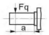 |
Fqmax | N | 2350 | 2750 | 3700 | 4300 | 5400 | 6100 | 81502) | 92002) |
| a | mm | 16 | 16 | 16 | 16 | 16 | 16 | 18 | 18 | ||
| Fuerza axial, máx.3) | 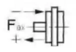 |
+Fax max | N | 320 | 320 | 320 | 500 | 500 | 500 | 630 | 800 |
| -Fax max | N | 320 | 320 | 320 | 500 | 500 | 500 | 630 | 800 | ||
| Permissible axial force/MPa operating pressure | ±Fax por/MPa | N/MPa | 30 | 30 | 30 | 52 | 52 | 52 | 70 | 87 | |
| Tamaño | 63 | 80 | 90 | 107 | 125 | 160 | 180 | |||
| Fuerza radial, máx.1) at distance a (from shaft collar) | 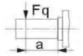 |
Fqmax | N | 10300 | 115002) | 12900 | 13600 | 15900 | 18400 | 20600 |
| a | mm | 18 | 20 | 20 | 20 | 20 | 25 | 25 | ||
| Fuerza axial, máx.3) | 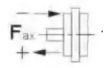 |
+Fax max | N | 800 | 1000 | 1000 | 12500 | 1250 | 1600 | 1600 |
| -Fax max | N | 800 | 1000 | 1000 | 12500 | 1250 | 1600 | 1600 | ||
| Permissible axial force/MPa operating pressure | ±Fax por/MPa | N/MPa | 87 | 106 | 106 | 129 | 129 | 167 | 167 | |
Presión mínima de entrada en el puerto de la línea de servicio A(B)
In order to avid damage of the motor a minimum inlet pressure at the inlet zone must be assured. The minimum inlet pressure is related to the rotational speed of the fixed motor.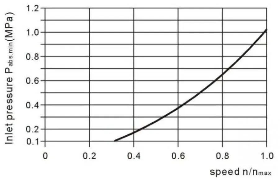 Póngase en contacto con nosotros si estas condiciones no se pueden cumplir.
Related Selection Resources
Request a A2FM Quotation
Tell us your required configuration, quantity and application.
Productos relacionados
Compare related hydraulic motors and confirm the complete configuration for your application.


Datos técnicos
Fluido hidráulico
El motor de desplazamiento fijo A2FM es adecuado para su uso con aceite mineral.
Rango de viscosidad
Recomendamos una viscosidad (a la temperatura de funcionamiento) óptima
fines de eficiencia y vida útil
Vopt= viscosidad óptima 16...36mm2/s
Se elegirá teniendo en cuenta la temperatura de circulación (circuito cerrado) y la temperatura del depósito (circuito abierto).
Límites del rango de viscosidad
Los siguientes valores aplican casos extremos:
Vmín=5mm2/s
a corto plazo (t < 3 min) a la temperatura máx. permitida
tmáx=115℃
Vmáx= 1600 mm2/s
a corto plazo (t < 3 min) con arranque en frío (P < 3 MPa,
n≤1000rpm tmín=-40 °C)
Tenga en cuenta que tampoco debe superarse localmente la temperatura máxima del fluido hidráulico (p. ej., en la zona de los cojinetes). La temperatura en la zona de los cojinetes es —en función de la presión y la velocidad— hasta 12 K superior a la temperatura media de drenaje de la carcasa.
Diagrama de selección
Detalles sobre la elección de fluido hidráulico
La elección correcta del fluido a presión requiere el conocimiento de la temperatura de funcionamiento en relación con la temperatura ambiente: en un circuito cerrado, la temperatura de circulación; en un circuito abierto, la temperatura del depósito.
El fluido hidráulico debe seleccionarse de modo que, dentro del rango de temperatura de servicio, la viscosidad de servicio se encuentre dentro del rango óptimo (υ opt) (véase la sección sombreada del diagrama de selección). Recomendamos seleccionar el rango de viscosidad más alto posible en cada caso.
A una temperatura ambiente de X℃, se establece una temperatura de funcionamiento de 60℃ en el circuito. En el rango de viscosidad de funcionamiento óptimo (υ opt; área sombreada), esto corresponde a las clases de viscosidad VG 46 o VG 68; a seleccionar: CG 68
Tenga en cuenta que la temperatura del fluido de fuga, que se ve afectada por la presión y la velocidad de giro, es siempre superior a la temperatura de circulación o del tanque. En ningún punto del sistema la temperatura puede ser superior a 115 ℃.
Filtración
Cuanto más fina es la filtración, más limpio es el fluido y mayor es la vida útil
de la unidad de pistones axiales.
Para garantizar el correcto funcionamiento de la unidad de pistones axiales, el fluido hidráulico debe tener un nivel de limpieza de al menos.
20/18/15 según la norma ISO 4406.
A temperaturas de fluido hidráulico muy altas (de 90 °C a máx. 115 °C), un nivel de limpieza de al menos.
Se requiere 19/17/14 según la norma ISO 4406.
Por favor, póngase en contacto con nosotros si no se pueden alcanzar estos niveles de limpieza.
Rango de presión de operación
Presión máxima en el puerto A o B
(datos de presión según DIN 24312)
| Extremo del eje A,Z | Extremo del eje B, P | |
| Presión nominal PN | 40 MPa | 35 MPa |
| Presión máxima Pmáx | 45 MPa | 40 MPa |
| presión de suma (A+B) | 70 MPa | 70 MPa |
Nota: en el extremo del eje Z y P, una presión nominal de PN= 31,5 MPa (Pmáx=35MPa) está permitido para el extremo del eje conducido que está sujeto a flexión transversal (piñones, correas en V) !
Talla 56 con extremo de eje Z:PN=35MPa, Pmáx= 40 MPa
En casos de carga pulsante superior a 31,5 MPa, recomendamos la versión con eje estriado A o eje estriado Z (tamaños 45).
Dirección del flujo
Rango de velocidad
Sin límite de velocidad mínima nmín. Si se requiere un movimiento uniforme,mín no debe ser inferior a 50 rpm.
Anillo de sello de eje
carga de presión admisible
La vida útil bajo presión del anillo de sello del eje se ve afectada por la velocidad del motor y la presión de drenaje de la carcasa. La carga permitida con presión de drenaje de la carcasa intermitente depende de la velocidad de rotación (ver tabla). Se permiten picos de presión a corto plazo (t<5 min) de hasta 1 MPa absoluto.
La presión de drenaje de la carcasa permanente promedio no debe exceder 0,3 MPa absolutos.
La presión en la caja debe ser igual o mayor que la presión externa en el sello del eje.
Rango de temperatura
El retén de eje de FKM es admisible para un rango de temperatura de alojamiento
de -25 °C a +115 °C
Tatabla de valores (valores teóricos, ignorando ηmín y ηv; valores redondeados
| Tamaño | 10 | 12 | 16 | 23 | 28 | 32 | 45 | |||
| Desplazamiento | Vg | mL/r | 10.3 | 12.0 | 16.0 | 22.9 | 28.1 | 32 | 45.6 | |
| Velocidad máxima | nmáx | mín-1 | 8000 | 8000 | 8000 | 6300 | 6300 | 6300 | 5600 | |
| nlímite máximo1) | mín-1 | 8800 | 8800 | 8800 | 6900 | 6900 | 6900 | 6200 | ||
| Caudal máx. | qvmax | L/min | 82 | 96 | 128 | 144 | 176 | 201 | 255 | |
| Constantes de par | TK | Nm/MPa | 1.64 | 1.9 | 2.5 | 3.6 | 4.45 | 5.09 | 7.25 | |
| Par en | Δp=35 MPa | T | Nm | 57 | 67 | 88 | 126 | 156 | 178 | 254 |
| Δp=40 MPa | T | Nm | 65 | 76 | 100 | 144 | 178 | 204 | 290 | |
| Capacidad de llenado | L | 0.17 | 0.17 | 0.17 | 0.20 | 0.20 | 0.20 | 0.33 | ||
| Momento de inercia de masa alrededor del eje de salida |
J | kgm2 | 0.0004 | 0.0004 | 0.0004 | 0.0012 | 0.0012 | 0.0012 | 0.0024 | |
| Masa (aprox.) | kg | 5.4 | 5.4 | 5.4 | 9.5 | 9.5 | 9.5 | 13.5 | ||
| Tamaño | 56 | 63 | 80 | 90 | 107 | 125 | 160 | 180 | |||
| Desplazamiento | Vg | mL/r | 56.1 | 63.0 | 80.4 | 90.0 | 106.7 | 125.0 | 160.4 | 180.0 | |
| Velocidad máxima | nmáx | mín-1 | 5000 | 5000 | 4500 | 4500 | 4000 | 4000 | 3600 | 3600 | |
| nlímite máximo1) | mín-1 | 5500 | 5500 | 5000 | 5000 | 4400 | 4400 | 4000 | 4000 | ||
| Caudal máx. | qvmax | L/min | 280 | 315 | 360 | 405 | 427 | 500 | 577 | 648 | |
| Constantes de par | TK | Nm/MPa | 8.9 | 10.0 | 12.7 | 17.0 | 19.9 | 25.4 | 28.6 | 31.8 | |
| Par en | Δp=35 MPa | T | Nm | 312 | 350 | 445 | 501 | 595 | 697 | 889 | 1001 |
| Δp=40 MPa | T | Nm | 356 | 400 | 508 | 572 | 680 | 796 | 1016 | 1144 | |
| Capacidad de llenado | L | 0.45 | 0.45 | 0.55 | 0.55 | 0.8 | 0.80 | 1.1 | 1.1 | ||
| Momento de inercia de masa alrededor del eje de salida |
J | kgm2 | 0.0042 | 0.0042 | 0.0072 | 0.0072 | 0.0116 | 0.0116 | 0.0220 | 0.0220 | |
| Masa (aprox.) | kg | 18 | 18 | 23 | 23 | 32 | 32 | 45 | 45 | ||
1) velocidad máxima intermitente: sobrevelocidad en operaciones de descarga y de recorrido por inercia, t<5 seg. y Δp<15MPa.
Determinación del tamaño
| Flujo | qv=(Vg∙n)/(1000∙ηv) | [L/min] | Vg=Cilindrada por revolución en mL/r Δp = Presión diferencial en MPa n=Velocidad en rpm ηvEficiencia volumétrica ηMh=Eficiencia mecánico-hidráulica ηt= Eficiencia general |
| velocidad | n=(qv∙1000∙ηv)/Vg | [rpm] | |
| Par de torsión | T=(Vg∙ Δp∙ηMh)/20π | [Nm] | |
| Poder | P=(2π∙T∙n)/60000=(qv∙Δp)/(600∙ηt) | [KW] |
Carga radial y axial admisible en el eje de transmisión
Los valores indicados son valores máximos y no se aplican al funcionamiento continuo
| Tamaño | 10 | 12 | 16 | 23 | 28 | 32 | 45 | 56 | |||
| Fuerza radial, máx.1) a distancia a (del collarín de eje) |
|
Fqmax | N | 2350 | 2750 | 3700 | 4300 | 5400 | 6100 | 81502) | 92002) |
| a | mm | 16 | 16 | 16 | 16 | 16 | 16 | 18 | 18 | ||
| Fuerza axial, máx.3) | |
+Fax max | N | 320 | 320 | 320 | 500 | 500 | 500 | 630 | 800 |
| -Fax max | N | 320 | 320 | 320 | 500 | 500 | 500 | 630 | 800 | ||
| Fuerza axial admisible / MPa presión de operación |
±Fax por/MPa | N/MPa | 30 | 30 | 30 | 52 | 52 | 52 | 70 | 87 | |
| Tamaño | 63 | 80 | 90 | 107 | 125 | 160 | 180 | |||
| Fuerza radial, máx.1) a distancia a (del collarín de eje) |
|
Fqmax | N | 10300 | 115002) | 12900 | 13600 | 15900 | 18400 | 20600 |
| a | mm | 18 | 20 | 20 | 20 | 20 | 25 | 25 | ||
| Fuerza axial, máx.3) | |
+Fax max | N | 800 | 1000 | 1000 | 12500 | 1250 | 1600 | 1600 |
| -Fax max | N | 800 | 1000 | 1000 | 12500 | 1250 | 1600 | 1600 | ||
| Fuerza axial admisible / MPa presión de operación |
±Fax por/MPa | N/MPa | 87 | 106 | 106 | 129 | 129 | 167 | 167 | |
1) durante el funcionamiento intermitente
2) fuerza radial máx. admisible con extremo de eje Z: Fq máx. = 6500 N
3) fuerza axial máx. admisible en parada o cuando la unidad de pistones axiales trabaja en condiciones sin presión
4) cuando está detenido o cuando la unidad de pistones axiales funciona en condiciones sin presión. Se permiten fuerzas mayores cuando está bajo presión.
Póngase en contacto con nosotros.
Al considerar la fuerza axial admisible, se debe tener en cuenta la dirección de transferencia de la fuerza:
-Fhacha máx = aumento de la vida útil de los rodamientos
+Fhacha máx =reducción de la vida útil de los rodamientos (evitar en la medida de lo posible)
Presión mínima de entrada en el puerto de la línea de servicio A(B)
Para evitar daños en el motor, se debe garantizar una presión de entrada mínima en la zona de entrada.
La presión mínima de entrada está relacionada con la velocidad de giro del motor fijo.
Póngase en contacto con nosotros si estas condiciones no se pueden cumplir.