Wenzhou Prance Hydraulic Equipment Co., Ltd

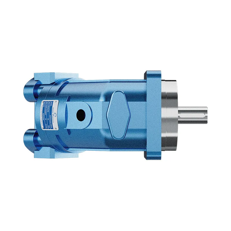


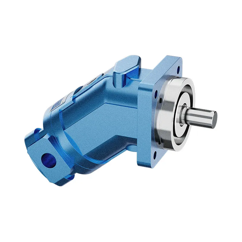
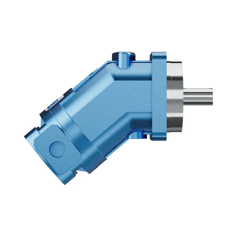
A2FM Fixed Displacement Bent Axis Motor
The A2FM fixed displacement motor converts hydraulic flow and pressure difference into shaft speed and torque. It is listed for open and closed circuits, provided the selected model meets the circuit pressure, drainage and installation conditions.
- Fixed displacement motor
- Bent-axis piston design
- Mobile and industrial applications
- Size and interfaces selected from the model code
PRANCE HYDRAULIC · PRODUCT SERIES
A2FM Fixed Displacement Bent Axis Motor
Axial piston; bent axis, fixed displacement · Open and closed circuits, subject to configuration
The A2FM fixed displacement motor converts hydraulic flow and pressure difference into shaft speed and torque. It is listed for open and closed circuits, provided the selected model meets the circuit pressure, drainage and installation conditions.
Model
✓
Request a QuotationVer Dados Técnicos e Folha de DadosA2FMAxial piston; bent axis, fixed displacement
Confirm the complete model and approved specification with Prance Hydraulic. Product-series references alone do not establish interchangeability.
Configuration review · Technical documentation · Product selection
Detalhes do Produto
- Fixed displacement motor
- Bent-axis piston design
- Mobile and industrial applications
- Size and interfaces selected from the model code
CATEGORIES: Motor de deslocamento fixo, Motor de pistões
A2FM Features & Application
Fixed displacement motor
For a fixed displacement, flow and speed remain linked by the selected displacement. Check the actual operating point and efficiency.
Bent-axis piston design
Specify the full MS order code, installation drawing and operating duty so the quotation can identify the proposed configuration.
Mobile and industrial applications
Check the required shaft torque and speed at the same operating point. Include starting duty, return pressure and external shaft loads.
Size and interfaces selected from the model code
Check pilot diameter, bolt pattern, shaft engagement or port pattern against the approved installation drawing.
A2FM Specifications
| Series / model | A2FM |
|---|---|
| Product type | A2FM Fixed Displacement Bent Axis Motor |
| Design | Axial piston; bent axis, fixed displacement |
| Circuit / selection | Open and closed circuits, subject to configuration |
| Controlo de deslocamento | Fixed |
| Fluido hidráulico | Mineral-oil use described; confirm other fluids and seal options individually |
A2FM Selection & Configuration
The A2FM fixed displacement motor converts hydraulic flow and pressure difference into shaft speed and torque. It is listed for open and closed circuits, provided the selected model meets the circuit pressure, drainage and installation conditions.
Choose displacement from the required torque-speed duty and available flow, then check external shaft loads and case pressure. Increasing supply pressure alone does not establish safe operation if the return or drain is restricted. Use the selected model data for continuous and peak conditions.
cURL Too many subrequests by single Worker invocation. To configure this limit, refer to https://developers.cloudflare.com/workers/wrangler/configuration/#limits.
cURL Too many subrequests by single Worker invocation. To configure this limit, refer to https://developers.cloudflare.com/workers/wrangler/configuration/#limits.
Hydraulic pumps · Hydraulic motors · Hydraulic valves
Send the MS nameplate, operating requirements and installation drawing for a configuration review before quoting.
- Model review — send the full model code or an existing nameplate photograph.
- Interface matching — confirm shaft, mounting flange, rotation and ports.
- Operating conditions — provide flow, pressure, speed, fluid and duty cycle.
- Documentation — request the relevant product data and drawings for your review.

A2FM Buying Guide
Use this sequence to prepare the A2FM configuration for review and quotation.
- Define starting and continuous torque, speed range and duty cycle.
- Specify available flow, work-port pressure difference and return pressure.
- Confirm the displacement setting and required behavior during starting and stopping.
- Check shaft, mounting pilot, flange, port orientation and external loads.
- Review case drainage, replenishment and any displacement control.
- Specify fluid conditions and any independent braking requirement.
- Approve the complete model, operating envelope, drawing and quantity.

Selection, Documentation & Project Support

Selection Support
Learn more →Share your hydraulic circuit, operating point and installation requirements for a configuration discussion.
Flow · Pressure · Speed · Interfaces

Technical Resources
Learn more →Review product documentation, model codes and technical data before finalizing the specification.
Datasheets · Model codes · Drawings

Project Inquiries
Learn more →Send your required model, quantity, application and project requirements to discuss your inquiry.
Product inquiries · Configuration review
Configuration, Quantity & Delivery
Confirm the complete MS code, approved drawing and operating limits. Availability, quantity, documentation and delivery date are confirmed in the quotation.
Discuss Your A2FM Application
Send the full model code, operating duty, installation details and quantity.
Request a A2FM QuotationA2FM Questions Before Ordering
What type of product is the A2FM?
AA2FM Fixed Displacement Bent Axis Motor. Design: Axial piston; bent axis, fixed displacement. Open and closed circuits, subject to configuration. Confirm the complete order code for the offered version.
Can a similar motor replace the A2FM?
cURL Too many subrequests by single Worker invocation. To configure this limit, refer to https://developers.cloudflare.com/workers/wrangler/configuration/#limits.
cURL Too many subrequests by single Worker invocation. To configure this limit, refer to https://developers.cloudflare.com/workers/wrangler/configuration/#limits
cURL Too many subrequests by single Worker invocation. To configure this limit, refer to https://developers.cloudflare.com/workers/wrangler/configuration/#limits.
A2FM Technical Data & Documents
View A2FM catalog data and operating conditions
cURL Too many subrequests by single Worker invocation. To configure this limit, refer to https://developers.cloudflare.com/workers/wrangler/configuration/#limits.
Dados Técnicos
Fluido hidráulico
O motor de cilindrada fixa A2FM é adequado para utilização com óleo mineral.Gama de viscosidade
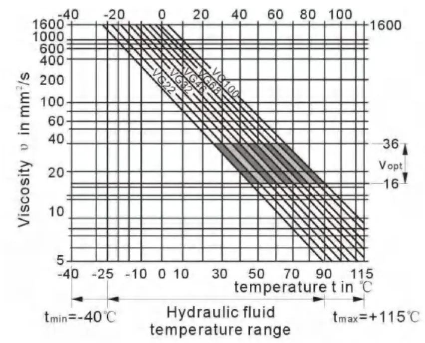
We recommend that a viscosity (at operating temperature)for optimum efficiency and service life purposes of Vopt= optimum viscosity 16…36mm2Ser escolhido, tendo em conta a temperatura de circulação (circuito fechado) e a temperatura do depósito (circuito aberto).Limites do intervalo de viscosidade
The following values apply extreme cases: Vmin=5mm2/s short term(t < 3 min) at max. permitted temperature tmáx=115℃ Vmáx=1600mm2/s short term (t<3 min) with cold start(P<3MPa, n≤1000rpm tminNote que a temperatura máxima do fluido hidráulico também não deve ser excedida localmente (por exemplo, na zona do rolamento). A temperatura na zona do rolamento é — dependendo da pressão e da velocidade — até 12 K superior à temperatura média de drenagem do cárter.Diagrama de seleção
Detalhes relativos à escolha de fluido hidráulico
The correct choice of pressure fluid requires knowledge of the operating temperature in relation to the ambient temperature:in a closed circuit the circulation temperature,in an open circuit the tank temperature. The hydraulic fluid should be selected so that within the operating temperature range,the operating viscosity lies within the optimum range (υ opt) (see shaded section of the selection diagram).We recommend that the highest possible viscosity range should be chosen in each case. Example:At an ambient temperature of X℃ an operating temperature of 60℃ is set in the circuit . In the optimum operating viscosity range (υ opt; shaded area) this corresponds to the viscosity classes VG 46 or VG68; to be selected: CG 68 Please note : The leakage fluid temperature, which is affected by pressure and rotational speed, is always higher than the circulation temperature or tank temperature. At no point in the system may t-he temperature be higher than 115℃.Filtração
The finer the filtration, the cleaner the fluid and the longer the service life of the axial piston unit. To ensure proper function of the axial piston unit, the hydraulic fluid must have a cleanliness level of least. 20/18/15 according to ISO 4406. At very high hydraulic fluid temperatures (90℃ to max. 115℃),a cleanliness level of at least. 19/17/14 according to ISO 4406 is required. Please contact us if these cleanliness levels cannot be achieved. Gama de pressão de funcionamento Maximum pressure on port A or B (pressure data according to DIN 24312)| Extremidade do eixo A,Z | Extremidade do veio B, P | |
| Pressão nominal PN | 40 MPa | 35 MPa |
| Pressão de pico Pmáx | 45 MPa | 40 MPa |
| pressão de somatório (A+B) | 70 MPa | 70 MPa |
Sentido do fluxo
Intervalo de velocidade
Sem limite para a velocidade mínima nmin. Se for necessário um movimento uniforme,min não deve ser inferior a 50 rpm.Anel vedante de veio
permissible pressure load The pressure service life of the shaft seal ring is affected by the speed of the motor and the case drain pressure. The permitted loading with intermittent case drain pressure depends on the rotational speed(see chart). Short-term (t<5 min) pressure spikes of up to 1 Mpa absolute are permitted. The average permanent case drain pressure must not exceed 0. 3Mpa absolute. The pressure in the case must be equal to or greater than the external pressure on the shaft seal.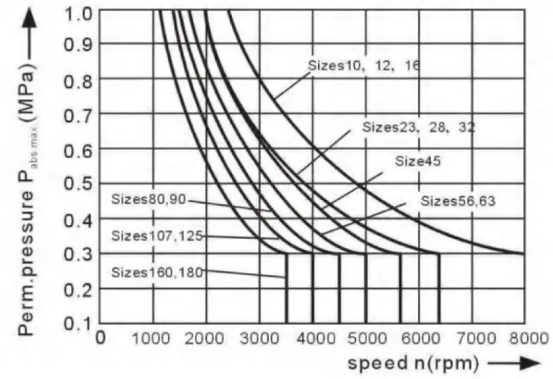
Gama de temperaturas
The FKM shaft seal is admissible for a housing temperature range from -25℃ to +115℃Tatabela de valores (valores teóricos, ignorando ηmin e ηv; valores arredondados)
| Tamanho | 10 | 12 | 16 | 23 | 28 | 32 | 45 | |||
| Deslocamento | Vg | mL/r | 10.3 | 12.0 | 16.0 | 22.9 | 28.1 | 32 | 45.6 | |
| Velocidade máxima | nmáx | min-1 | 8000 | 8000 | 8000 | 6300 | 6300 | 6300 | 5600 | |
| nlimite máximo1) | min-1 | 8800 | 8800 | 8800 | 6900 | 6900 | 6900 | 6200 | ||
| Caudal máximo. | qvmax | L/min | 82 | 96 | 128 | 144 | 176 | 201 | 255 | |
| Constantes de binário | TK | Nm/MPa | 1.64 | 1.9 | 2.5 | 3.6 | 4.45 | 5.09 | 7.25 | |
| Binário às | Δp=35 MPa | T | Nm | 57 | 67 | 88 | 126 | 156 | 178 | 254 |
| Δp=40 MPa | T | Nm | 65 | 76 | 100 | 144 | 178 | 204 | 290 | |
| Capacidade de enchimento | L | 0.17 | 0.17 | 0.17 | 0.20 | 0.20 | 0.20 | 0.33 | ||
| Mass moment of inertia around output shaft | J | kgm2 | 0.0004 | 0.0004 | 0.0004 | 0.0012 | 0.0012 | 0.0012 | 0.0024 | |
| Massa (aprox.) | kg | 5.4 | 5.4 | 5.4 | 9.5 | 9.5 | 9.5 | 13.5 | ||
| Tamanho | 56 | 63 | 80 | 90 | 107 | 125 | 160 | 180 | |||
| Deslocamento | Vg | mL/r | 56.1 | 63.0 | 80.4 | 90.0 | 106.7 | 125.0 | 160.4 | 180.0 | |
| Velocidade máxima | nmáx | min-1 | 5000 | 5000 | 4500 | 4500 | 4000 | 4000 | 3600 | 3600 | |
| nlimite máximo1) | min-1 | 5500 | 5500 | 5000 | 5000 | 4400 | 4400 | 4000 | 4000 | ||
| Caudal máximo. | qvmax | L/min | 280 | 315 | 360 | 405 | 427 | 500 | 577 | 648 | |
| Constantes de binário | TK | Nm/MPa | 8.9 | 10.0 | 12.7 | 17.0 | 19.9 | 25.4 | 28.6 | 31.8 | |
| Binário às | Δp=35 MPa | T | Nm | 312 | 350 | 445 | 501 | 595 | 697 | 889 | 1001 |
| Δp=40 MPa | T | Nm | 356 | 400 | 508 | 572 | 680 | 796 | 1016 | 1144 | |
| Capacidade de enchimento | L | 0.45 | 0.45 | 0.55 | 0.55 | 0.8 | 0.80 | 1.1 | 1.1 | ||
| Mass moment of inertia around output shaft | J | kgm2 | 0.0042 | 0.0042 | 0.0072 | 0.0072 | 0.0116 | 0.0116 | 0.0220 | 0.0220 | |
| Massa (aprox.) | kg | 18 | 18 | 23 | 23 | 32 | 32 | 45 | 45 | ||
Determinar o tamanho
| Fluxo | qv=(Vg∙n)/(1000∙ηv) | [L/min] | Vg=Displacement per revolution in mL/r Δp=Differential pressure in MPa n=Speed in rpm ηv=Volumetric efficiency ηmh=Mechanical-hydraulic efficiency ηt=Eficiência global |
| velocidade | n=(qv∙1000∙ηv)/Vg | [rpm] | |
| Binário | T=(Vg∙ Δp∙ηmh)/20π | [Nm] | |
| Energia | P=(2π∙T∙n)/60000=(qv∙Δp)/(600∙ηt) | [KW] |
| Tamanho | 10 | 12 | 16 | 23 | 28 | 32 | 45 | 56 | |||
| Força radial, máx.1) at distance a (from shaft collar) | 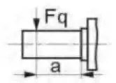 |
Fqmax | N | 2350 | 2750 | 3700 | 4300 | 5400 | 6100 | 81502) | 92002) |
| a | mm | 16 | 16 | 16 | 16 | 16 | 16 | 18 | 18 | ||
| Força axial, máx.3) | 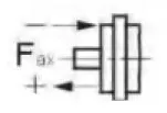 |
+Fax max | N | 320 | 320 | 320 | 500 | 500 | 500 | 630 | 800 |
| -Fax max | N | 320 | 320 | 320 | 500 | 500 | 500 | 630 | 800 | ||
| Permissible axial force/MPa operating pressure | ±Fax por/MPa | N/MPa | 30 | 30 | 30 | 52 | 52 | 52 | 70 | 87 | |
| Tamanho | 63 | 80 | 90 | 107 | 125 | 160 | 180 | |||
| Força radial, máx.1) at distance a (from shaft collar) | 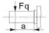 |
Fqmax | N | 10300 | 115002) | 12900 | 13600 | 15900 | 18400 | 20600 |
| a | mm | 18 | 20 | 20 | 20 | 20 | 25 | 25 | ||
| Força axial, máx.3) | 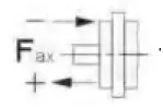 |
+Fax max | N | 800 | 1000 | 1000 | 12500 | 1250 | 1600 | 1600 |
| -Fax max | N | 800 | 1000 | 1000 | 12500 | 1250 | 1600 | 1600 | ||
| Permissible axial force/MPa operating pressure | ±Fax por/MPa | N/MPa | 87 | 106 | 106 | 129 | 129 | 167 | 167 | |
Pressão mínima de entrada na porta A(B) da linha de serviço
In order to avid damage of the motor a minimum inlet pressure at the inlet zone must be assured. The minimum inlet pressure is related to the rotational speed of the fixed motor.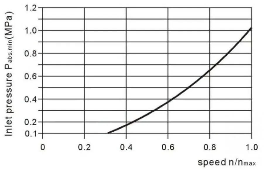 Contacte-nos caso estas condições não possam ser cumpridas.
Related Selection Resources
Request a A2FM Quotation
Tell us your required configuration, quantity and application.
Produtos Relacionados
Compare related hydraulic motors and confirm the complete configuration for your application.


Dados Técnicos
Fluido hidráulico
O motor de cilindrada fixa A2FM é adequado para utilização com óleo mineral.
Gama de viscosidade
Recomendamos uma viscosidade (à temperatura de funcionamento) para o ótimo
fins de eficiência e durabilidade
Vopt= viscosidade ótima 16...36mm2/s
Ser escolhido, tendo em conta a temperatura de circulação (circuito fechado) e a temperatura do depósito (circuito aberto).
Limites do intervalo de viscosidade
Os seguintes valores aplicam-se a casos extremos:
Vmin=5mm2/s
curto prazo (t < 3 min) à temperatura máx. permitida
tmáx=115℃
Vmáx=1600mm2/s
curto prazo (t<3 min) com arranque a frio (P<3MPa,
n≤1000rpm tmin=-40°C)
Note que a temperatura máxima do fluido hidráulico também não deve ser excedida localmente (por exemplo, na zona do rolamento). A temperatura na zona do rolamento é — dependendo da pressão e da velocidade — até 12 K superior à temperatura média de drenagem do cárter.
Diagrama de seleção
Detalhes relativos à escolha de fluido hidráulico
A escolha correcta do fluido de pressão requer o conhecimento da temperatura de funcionamento em relação à temperatura ambiente: num circuito fechado, a temperatura de circulação; num circuito aberto, a temperatura do depósito.
O fluido hidráulico deve ser selecionado de modo que, dentro da gama de temperaturas de funcionamento, a viscosidade de funcionamento se situe na gama ideal ($\upsilon$ opt) (ver a secção a sombreado no diagrama de seleção). Recomendamos que seja escolhida a gama de viscosidade mais elevada possível em cada caso.
A uma temperatura ambiente de X℃, é definida uma temperatura de funcionamento de 60℃ no circuito. Na gama de viscosidade de funcionamento ideal (υ opt; área sombreada), isto corresponde às classes de viscosidade VG 46 ou VG 68; a selecionar: CG 68
Nota: A temperatura do fluido de fuga, que é afetada pela pressão e pela velocidade de rotação, é sempre superior à temperatura de circulação ou à temperatura do depósito. Em nenhum ponto do sistema a temperatura pode ser superior a 115℃.
Filtração
Quanto mais fina a filtração, mais limpo o fluido e maior a vida útil
da unidade de pistões axiais.
Para garantir o funcionamento adequado da unidade de pistões axiais, o fluido hidráulico deve ter um nível de limpeza de pelo menos.
20/18/15 de acordo com a norma ISO 4406.
A temperaturas de fluido hidráulico muito elevadas (90 °C até máx. 115 °C), um nível de limpeza de pelo menos.
É necessário 19/17/14 de acordo com a norma ISO 4406.
Por favor, contacte-nos caso não seja possível atingir estes níveis de limpeza.
Gama de pressão de funcionamento
Pressão máxima na porta A ou B
(dados de pressão de acordo com a norma DIN 24312)
| Extremidade do eixo A,Z | Extremidade do veio B, P | |
| Pressão nominal PN | 40 MPa | 35 MPa |
| Pressão de pico Pmáx | 45 MPa | 40 MPa |
| pressão de somatório (A+B) | 70 MPa | 70 MPa |
Atenção: na extremidade do veio Z e P, uma pressão nominal de PN=31,5MPa (Pmáx=35MPa) é permitido para a extremidade do eixo acionado que está sujeita a flexão transversal (carretos, correias em V) !
Tamanho 56 com extremidade de eixo Z:PN=35MPa, Pmáx=40MPa
em casos de carregamento pulsatório superior a 31,5 MPa, recomendamos a versão com veio ranhurado A ou veio ranhurado Z (tamanhos 45)
Sentido do fluxo
Intervalo de velocidade
Sem limite para a velocidade mínima nmin. Se for necessário um movimento uniforme,min não deve ser inferior a 50 rpm.
Anel vedante de veio
carga de pressão admissível
A durabilidade sob pressão do anel vedador do veio é afetada pela velocidade do motor e pela pressão de drenagem da caixa. A carga permitida com pressão de drenagem da caixa intermitente depende da velocidade de rotação (ver gráfico). Picos de pressão de curto prazo (t<5 min) até 1 MPa absoluto são permitidos.
A pressão média permanente de drenagem da caixa não deve exceder 0,3 MPa absoluto.
A pressão no interior da carcaça deve ser igual ou superior à pressão externa no selo do veio.
Gama de temperaturas
O retentor de veio FKM é admissível para um intervalo de temperatura do alojamento
de -25℃ a +115℃
Tatabela de valores (valores teóricos, ignorando ηmin e ηv; valores arredondados)
| Tamanho | 10 | 12 | 16 | 23 | 28 | 32 | 45 | |||
| Deslocamento | Vg | mL/r | 10.3 | 12.0 | 16.0 | 22.9 | 28.1 | 32 | 45.6 | |
| Velocidade máxima | nmáx | min-1 | 8000 | 8000 | 8000 | 6300 | 6300 | 6300 | 5600 | |
| nlimite máximo1) | min-1 | 8800 | 8800 | 8800 | 6900 | 6900 | 6900 | 6200 | ||
| Caudal máximo. | qvmax | L/min | 82 | 96 | 128 | 144 | 176 | 201 | 255 | |
| Constantes de binário | TK | Nm/MPa | 1.64 | 1.9 | 2.5 | 3.6 | 4.45 | 5.09 | 7.25 | |
| Binário às | Δp=35 MPa | T | Nm | 57 | 67 | 88 | 126 | 156 | 178 | 254 |
| Δp=40 MPa | T | Nm | 65 | 76 | 100 | 144 | 178 | 204 | 290 | |
| Capacidade de enchimento | L | 0.17 | 0.17 | 0.17 | 0.20 | 0.20 | 0.20 | 0.33 | ||
| momento de inércia mássico em redor do veio de saída |
J | kgm2 | 0.0004 | 0.0004 | 0.0004 | 0.0012 | 0.0012 | 0.0012 | 0.0024 | |
| Massa (aprox.) | kg | 5.4 | 5.4 | 5.4 | 9.5 | 9.5 | 9.5 | 13.5 | ||
| Tamanho | 56 | 63 | 80 | 90 | 107 | 125 | 160 | 180 | |||
| Deslocamento | Vg | mL/r | 56.1 | 63.0 | 80.4 | 90.0 | 106.7 | 125.0 | 160.4 | 180.0 | |
| Velocidade máxima | nmáx | min-1 | 5000 | 5000 | 4500 | 4500 | 4000 | 4000 | 3600 | 3600 | |
| nlimite máximo1) | min-1 | 5500 | 5500 | 5000 | 5000 | 4400 | 4400 | 4000 | 4000 | ||
| Caudal máximo. | qvmax | L/min | 280 | 315 | 360 | 405 | 427 | 500 | 577 | 648 | |
| Constantes de binário | TK | Nm/MPa | 8.9 | 10.0 | 12.7 | 17.0 | 19.9 | 25.4 | 28.6 | 31.8 | |
| Binário às | Δp=35 MPa | T | Nm | 312 | 350 | 445 | 501 | 595 | 697 | 889 | 1001 |
| Δp=40 MPa | T | Nm | 356 | 400 | 508 | 572 | 680 | 796 | 1016 | 1144 | |
| Capacidade de enchimento | L | 0.45 | 0.45 | 0.55 | 0.55 | 0.8 | 0.80 | 1.1 | 1.1 | ||
| momento de inércia mássico em redor do veio de saída |
J | kgm2 | 0.0042 | 0.0042 | 0.0072 | 0.0072 | 0.0116 | 0.0116 | 0.0220 | 0.0220 | |
| Massa (aprox.) | kg | 18 | 18 | 23 | 23 | 32 | 32 | 45 | 45 | ||
1) velocidade máxima intermitente: excesso de velocidade na descarga e operações de translação em sobrecurso, t<5 seg. e Δp<15MPa.
Determinar o tamanho
| Fluxo | qv=(Vg∙n)/(1000∙ηv) | [L/min] | VgDeslocamento por rotação em mL/r Δp=Pressão diferencial em MPa n=Velocidade em rpm ηv=Eficiência volumétrica ηmhEficiência mecânico-hidráulica ηt=Eficiência global |
| velocidade | n=(qv∙1000∙ηv)/Vg | [rpm] | |
| Binário | T=(Vg∙ Δp∙ηmh)/20π | [Nm] | |
| Energia | P=(2π∙T∙n)/60000=(qv∙Δp)/(600∙ηt) | [KW] |
Carga radial e axial admissível no veio de accionamento
Os valores fornecidos são valores máximos e não se aplicam a funcionamento contínuo
| Tamanho | 10 | 12 | 16 | 23 | 28 | 32 | 45 | 56 | |||
| Força radial, máx.1) à distância a (do anel de fixação) |
|
Fqmax | N | 2350 | 2750 | 3700 | 4300 | 5400 | 6100 | 81502) | 92002) |
| a | mm | 16 | 16 | 16 | 16 | 16 | 16 | 18 | 18 | ||
| Força axial, máx.3) | |
+Fax max | N | 320 | 320 | 320 | 500 | 500 | 500 | 630 | 800 |
| -Fax max | N | 320 | 320 | 320 | 500 | 500 | 500 | 630 | 800 | ||
| Força axial admissível/MPa pressão de funcionamento |
±Fax por/MPa | N/MPa | 30 | 30 | 30 | 52 | 52 | 52 | 70 | 87 | |
| Tamanho | 63 | 80 | 90 | 107 | 125 | 160 | 180 | |||
| Força radial, máx.1) à distância a (do anel de fixação) |
|
Fqmax | N | 10300 | 115002) | 12900 | 13600 | 15900 | 18400 | 20600 |
| a | mm | 18 | 20 | 20 | 20 | 20 | 25 | 25 | ||
| Força axial, máx.3) | |
+Fax max | N | 800 | 1000 | 1000 | 12500 | 1250 | 1600 | 1600 |
| -Fax max | N | 800 | 1000 | 1000 | 12500 | 1250 | 1600 | 1600 | ||
| Força axial admissível/MPa pressão de funcionamento |
±Fax por/MPa | N/MPa | 87 | 106 | 106 | 129 | 129 | 167 | 167 | |
1) durante o funcionamento intermitente
2) força radial máx. admissível com extremidade do veio Z: Fq máx = 6500N
3) força axial máx. admissível com a unidade de pistões axiais parada ou a funcionar em condições isentas de pressão
4) quando parado ou quando a unidade de pistões axiais trabalha sem pressão. São permitidas forças maiselevadas sob pressão.
Por favor, contacte-nos.
Ao considerar a força axial admissível, deve ter-se em conta a direção de transferência da força:
-Fmachado máx = aumento da vida útil dos rolamentos
+Fmachado máx =redução da vida útil dos rolamentos (evitar a todo o custo)
Pressão mínima de entrada na porta A(B) da linha de serviço
Para evitar danos no motor, deve ser garantida uma pressão mínima de admissão na zona de entrada.
A pressão mínima de entrada está relacionada com a velocidade de rotação do motor fixo.
Contacte-nos caso estas condições não possam ser cumpridas.