Wenzhou Prance Hydraulic Equipment Co., Ltd.

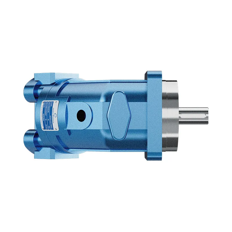


A2FM Fixed Displacement Bent Axis Motor
The A2FM fixed displacement motor converts hydraulic flow and pressure difference into shaft speed and torque. It is listed for open and closed circuits, provided the selected model meets the circuit pressure, drainage and installation conditions.
- Fixed displacement motor
- Bent-axis piston design
- Mobile and industrial applications
- Size and interfaces selected from the model code
PRANCE HYDRAULIC · PRODUCT SERIES
A2FM Fixed Displacement Bent Axis Motor
Axial piston; bent axis, fixed displacement · Open and closed circuits, subject to configuration
The A2FM fixed displacement motor converts hydraulic flow and pressure difference into shaft speed and torque. It is listed for open and closed circuits, provided the selected model meets the circuit pressure, drainage and installation conditions.
Model
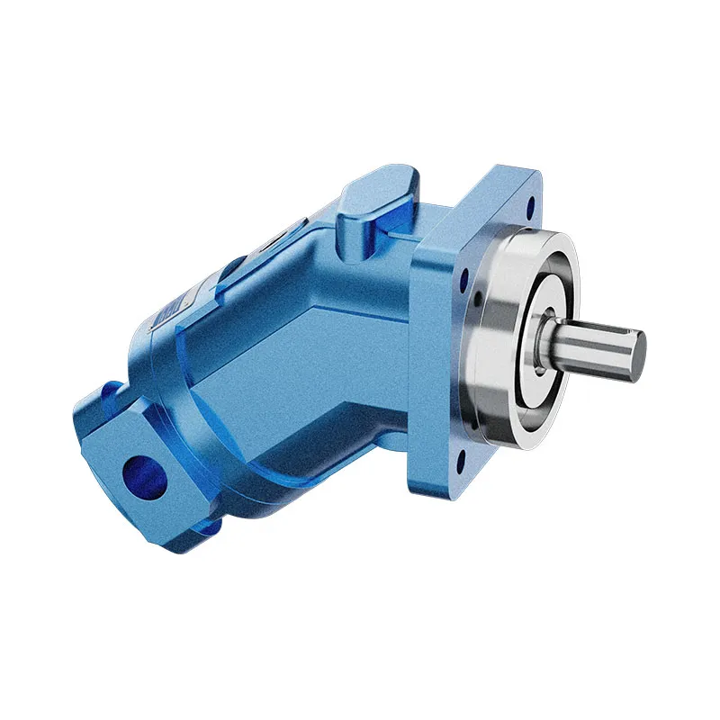
✓
Request a QuotationTechnische Daten & Datenblatt anzeigenA2FMAxial piston; bent axis, fixed displacement
Confirm the complete model and approved specification with Prance Hydraulic. Product-series references alone do not establish interchangeability.
Configuration review · Technical documentation · Product selection
Produktdetails
- Fixed displacement motor
- Bent-axis piston design
- Mobile and industrial applications
- Size and interfaces selected from the model code
CATEGORIES: Konstantmotor, Kolbenmotor
A2FM Features & Application
Fixed displacement motor
For a fixed displacement, flow and speed remain linked by the selected displacement. Check the actual operating point and efficiency.
Bent-axis piston design
Specify the full MS order code, installation drawing and operating duty so the quotation can identify the proposed configuration.
Mobile and industrial applications
Check the required shaft torque and speed at the same operating point. Include starting duty, return pressure and external shaft loads.
Size and interfaces selected from the model code
Check pilot diameter, bolt pattern, shaft engagement or port pattern against the approved installation drawing.
A2FM Specifications
| Series / model | A2FM |
|---|---|
| Product type | A2FM Fixed Displacement Bent Axis Motor |
| Design | Axial piston; bent axis, fixed displacement |
| Circuit / selection | Open and closed circuits, subject to configuration |
| Hubregelung | Fixed |
| Hydraulikflüssigkeit | Mineral-oil use described; confirm other fluids and seal options individually |
A2FM Selection & Configuration
The A2FM fixed displacement motor converts hydraulic flow and pressure difference into shaft speed and torque. It is listed for open and closed circuits, provided the selected model meets the circuit pressure, drainage and installation conditions.
Choose displacement from the required torque-speed duty and available flow, then check external shaft loads and case pressure. Increasing supply pressure alone does not establish safe operation if the return or drain is restricted. Use the selected model data for continuous and peak conditions.
cURL Too many subrequests by single Worker invocation. To configure this limit, refer to https://developers.cloudflare.com/workers/wrangler/configuration/#limits.
cURL Too many subrequests by single Worker invocation. To configure this limit, refer to https://developers.cloudflare.com/workers/wrangler/configuration/#limits.
Hydraulic pumps · Hydraulic motors · Hydraulic valves
Send the MS nameplate, operating requirements and installation drawing for a configuration review before quoting.
- Model review — send the full model code or an existing nameplate photograph.
- Interface matching — confirm shaft, mounting flange, rotation and ports.
- Operating conditions — provide flow, pressure, speed, fluid and duty cycle.
- Documentation — request the relevant product data and drawings for your review.

A2FM Buying Guide
Use this sequence to prepare the A2FM configuration for review and quotation.
- Define starting and continuous torque, speed range and duty cycle.
- Specify available flow, work-port pressure difference and return pressure.
- Confirm the displacement setting and required behavior during starting and stopping.
- Check shaft, mounting pilot, flange, port orientation and external loads.
- Review case drainage, replenishment and any displacement control.
- Specify fluid conditions and any independent braking requirement.
- Approve the complete model, operating envelope, drawing and quantity.

Selection, Documentation & Project Support

Selection Support
Learn more →Share your hydraulic circuit, operating point and installation requirements for a configuration discussion.
Flow · Pressure · Speed · Interfaces

Technical Resources
Learn more →Review product documentation, model codes and technical data before finalizing the specification.
Datasheets · Model codes · Drawings

Project Inquiries
Learn more →Send your required model, quantity, application and project requirements to discuss your inquiry.
Product inquiries · Configuration review
Configuration, Quantity & Delivery
Confirm the complete MS code, approved drawing and operating limits. Availability, quantity, documentation and delivery date are confirmed in the quotation.
Discuss Your A2FM Application
Send the full model code, operating duty, installation details and quantity.
Request a A2FM QuotationA2FM Questions Before Ordering
What type of product is the A2FM?
AA2FM Fixed Displacement Bent Axis Motor. Design: Axial piston; bent axis, fixed displacement. Open and closed circuits, subject to configuration. Confirm the complete order code for the offered version.
Can a similar motor replace the A2FM?
cURL Too many subrequests by single Worker invocation. To configure this limit, refer to https://developers.cloudflare.com/workers/wrangler/configuration/#limits.
cURL Too many subrequests by single Worker invocation. To configure this limit, refer to https://developers.cloudflare.com/workers/wrangler/configuration/#limits
cURL Too many subrequests by single Worker invocation. To configure this limit, refer to https://developers.cloudflare.com/workers/wrangler/configuration/#limits.
A2FM Technical Data & Documents
View A2FM catalog data and operating conditions
cURL Too many subrequests by single Worker invocation. To configure this limit, refer to https://developers.cloudflare.com/workers/wrangler/configuration/#limits.
Technische Daten
Hydraulikflüssigkeit
Der Konstantmotor A2FM ist für die Verwendung mit Mineralöl geeignet.Viskositätsbereich
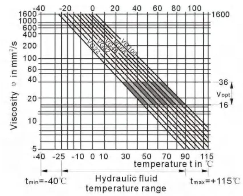
We recommend that a viscosity (at operating temperature)for optimum efficiency and service life purposes of VOPt= optimum viscosity 16…36mm2Wählen Sie unter Berücksichtigung der Umlaufreißtemperatur (geschlossener Kreislauf) und der Behältereinlasstemperatur (offener Kreislauf).Grenzen des Viskositätsbereichs
The following values apply extreme cases: Vmin.=5mm2/s short term(t < 3 min) at max. permitted temperature tMax=115℃ VMax= 1600 mm2/s short term (t<3 min) with cold start(P<3MPa, n≤1000rpm tmin.Beachten Sie, dass die maximale Hydraulikflüssigkeitstemperatur auch lokal (z. B. im Lagerbereich) nicht überschritten werden darf. Die Temperatur im Lagerbereich ist – abhängig von Druck und Drehzahl – bis zu 12 K höher als die durchschnittliche Gehäusespültemperatur.Auswahldiagramm
Details zur Auswahl von Hydraulikflüssigkeit
The correct choice of pressure fluid requires knowledge of the operating temperature in relation to the ambient temperature:in a closed circuit the circulation temperature,in an open circuit the tank temperature. The hydraulic fluid should be selected so that within the operating temperature range,the operating viscosity lies within the optimum range (υ opt) (see shaded section of the selection diagram).We recommend that the highest possible viscosity range should be chosen in each case. Example:At an ambient temperature of X℃ an operating temperature of 60℃ is set in the circuit . In the optimum operating viscosity range (υ opt; shaded area) this corresponds to the viscosity classes VG 46 or VG68; to be selected: CG 68 Please note : The leakage fluid temperature, which is affected by pressure and rotational speed, is always higher than the circulation temperature or tank temperature. At no point in the system may t-he temperature be higher than 115℃.Filtration
The finer the filtration, the cleaner the fluid and the longer the service life of the axial piston unit. To ensure proper function of the axial piston unit, the hydraulic fluid must have a cleanliness level of least. 20/18/15 according to ISO 4406. At very high hydraulic fluid temperatures (90℃ to max. 115℃),a cleanliness level of at least. 19/17/14 according to ISO 4406 is required. Please contact us if these cleanliness levels cannot be achieved. Betriebsdruckbereich Maximum pressure on port A or B (pressure data according to DIN 24312)| Wellenende A,Z | Wellenende B, P | |
| Nenndruck PN | 40 MPa | 35 MPa |
| Spitzendruck PMax | 45 MPa | 40 MPa |
| Summationsdruck (A+B) | 70 MPa | 70 MPa |
Fließrichtung
Geschwindigkeitsbereich
Keine Begrenzung der Mindestdrehzahl nmin.. Wenn eine gleichförmige Bewegung erforderlich ist,min. darf 50 U/min nicht unterschreiten.Wellendichtring
permissible pressure load The pressure service life of the shaft seal ring is affected by the speed of the motor and the case drain pressure. The permitted loading with intermittent case drain pressure depends on the rotational speed(see chart). Short-term (t<5 min) pressure spikes of up to 1 Mpa absolute are permitted. The average permanent case drain pressure must not exceed 0. 3Mpa absolute. The pressure in the case must be equal to or greater than the external pressure on the shaft seal.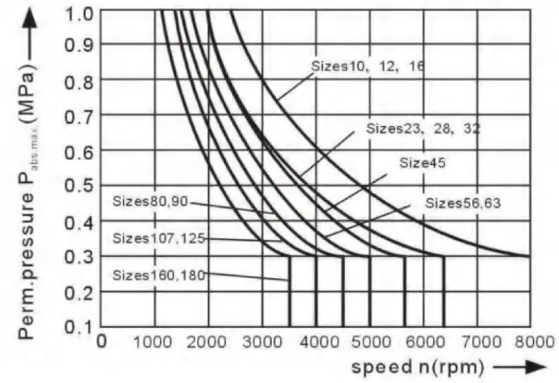
Temperaturbereich
The FKM shaft seal is admissible for a housing temperature range from -25℃ to +115℃TaWertetabelle (theoretische Werte, ignorierend ηmin. und ηv; gerundete Werte
| Größe | 10 | 12 | 16 | 23 | 28 | 32 | 45 | |||
| Verschiebung | Vg | mL/r | 10.3 | 12.0 | 16.0 | 22.9 | 28.1 | 32 | 45.6 | |
| Höchstgeschwindigkeit | nMax | min.-1 | 8000 | 8000 | 8000 | 6300 | 6300 | 6300 | 5600 | |
| nHöchstlimit1) | min.-1 | 8800 | 8800 | 8800 | 6900 | 6900 | 6900 | 6200 | ||
| Maximaler Durchfluss. | qVmax | l/min | 82 | 96 | 128 | 144 | 176 | 201 | 255 | |
| Drehmomentkonstanten | TK | Nm/MPa | 1.64 | 1.9 | 2.5 | 3.6 | 4.45 | 5.09 | 7.25 | |
| Drehmoment bei | Δp=35 MPa | T | Machs gut | 57 | 67 | 88 | 126 | 156 | 178 | 254 |
| Δp = 40 MPa | T | Machs gut | 65 | 76 | 100 | 144 | 178 | 204 | 290 | |
| Füllmenge | L | 0.17 | 0.17 | 0.17 | 0.20 | 0.20 | 0.20 | 0.33 | ||
| Mass moment of inertia around output shaft | J | kgm2 | 0.0004 | 0.0004 | 0.0004 | 0.0012 | 0.0012 | 0.0012 | 0.0024 | |
| Masse (ca.) | kg | 5.4 | 5.4 | 5.4 | 9.5 | 9.5 | 9.5 | 13.5 | ||
| Größe | 56 | 63 | 80 | 90 | 107 | 125 | 160 | 180 | |||
| Verschiebung | Vg | mL/r | 56.1 | 63.0 | 80.4 | 90.0 | 106.7 | 125.0 | 160.4 | 180.0 | |
| Höchstgeschwindigkeit | nMax | min.-1 | 5000 | 5000 | 4500 | 4500 | 4000 | 4000 | 3600 | 3600 | |
| nHöchstlimit1) | min.-1 | 5500 | 5500 | 5000 | 5000 | 4400 | 4400 | 4000 | 4000 | ||
| Maximaler Durchfluss. | qVmax | l/min | 280 | 315 | 360 | 405 | 427 | 500 | 577 | 648 | |
| Drehmomentkonstanten | TK | Nm/MPa | 8.9 | 10.0 | 12.7 | 17.0 | 19.9 | 25.4 | 28.6 | 31.8 | |
| Drehmoment bei | Δp=35 MPa | T | Machs gut | 312 | 350 | 445 | 501 | 595 | 697 | 889 | 1001 |
| Δp = 40 MPa | T | Machs gut | 356 | 400 | 508 | 572 | 680 | 796 | 1016 | 1144 | |
| Füllmenge | L | 0.45 | 0.45 | 0.55 | 0.55 | 0.8 | 0.80 | 1.1 | 1.1 | ||
| Mass moment of inertia around output shaft | J | kgm2 | 0.0042 | 0.0042 | 0.0072 | 0.0072 | 0.0116 | 0.0116 | 0.0220 | 0.0220 | |
| Masse (ca.) | kg | 18 | 18 | 23 | 23 | 32 | 32 | 45 | 45 | ||
Bestimmung der Größe
| Fluss | qv=(Vg∙n)/(1000∙ηv) | [l/min] | Vg=Displacement per revolution in mL/r Δp=Differential pressure in MPa n=Speed in rpm ηv=Volumetric efficiency ηmh=Mechanical-hydraulic efficiency ηt= Gesamteffizienz |
| Geschwindigkeit | n=(qv∙1000∙ηv)/Vg | U/min | |
| Drehmoment | T=(Vg∙ Δp∙ηmh)/20π | [Nm] | |
| Macht | P=(2π∙T∙n)/60000=(qv∙Δp)/(600∙ηt) | [KW] |
| Größe | 10 | 12 | 16 | 23 | 28 | 32 | 45 | 56 | |||
| Radiale Kraft, max.1) at distance a (from shaft collar) | 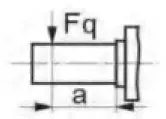 |
FQmax | N | 2350 | 2750 | 3700 | 4300 | 5400 | 6100 | 81502) | 92002) |
| a | mm | 16 | 16 | 16 | 16 | 16 | 16 | 18 | 18 | ||
| Axialkraft, max.3) | 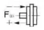 |
+FAch, Max | N | 320 | 320 | 320 | 500 | 500 | 500 | 630 | 800 |
| -FAch, Max | N | 320 | 320 | 320 | 500 | 500 | 500 | 630 | 800 | ||
| Permissible axial force/MPa operating pressure | ±Fax pro/MPa | N/MPa | 30 | 30 | 30 | 52 | 52 | 52 | 70 | 87 | |
| Größe | 63 | 80 | 90 | 107 | 125 | 160 | 180 | |||
| Radiale Kraft, max.1) at distance a (from shaft collar) | 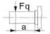 |
FQmax | N | 10300 | 115002) | 12900 | 13600 | 15900 | 18400 | 20600 |
| a | mm | 18 | 20 | 20 | 20 | 20 | 25 | 25 | ||
| Axialkraft, max.3) | 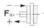 |
+FAch, Max | N | 800 | 1000 | 1000 | 12500 | 1250 | 1600 | 1600 |
| -FAch, Max | N | 800 | 1000 | 1000 | 12500 | 1250 | 1600 | 1600 | ||
| Permissible axial force/MPa operating pressure | ±Fax pro/MPa | N/MPa | 87 | 106 | 106 | 129 | 129 | 167 | 167 | |
Minimaler Eingangsdruck am Steueranschluss A(B)
In order to avid damage of the motor a minimum inlet pressure at the inlet zone must be assured. The minimum inlet pressure is related to the rotational speed of the fixed motor.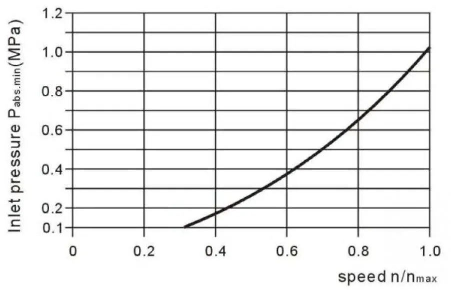 Bitte kontaktieren Sie uns, wenn diese Bedingungen nicht erfüllt werden können.
Related Selection Resources
Request a A2FM Quotation
Tell us your required configuration, quantity and application.
Ähnliche Produkte
Compare related hydraulic motors and confirm the complete configuration for your application.


Technische Daten
Hydraulikflüssigkeit
Der Konstantmotor A2FM ist für die Verwendung mit Mineralöl geeignet.
Viskositätsbereich
Wir empfehlen eine Viskosität (bei Betriebstemperatur) für eine optimale
Effizienz- und Lebensdauerzwecken
VOPt= optimale Viskosität 16...36 mm2/s
Wählen Sie unter Berücksichtigung der Umlaufreißtemperatur (geschlossener Kreislauf) und der Behältereinlasstemperatur (offener Kreislauf).
Grenzen des Viskositätsbereichs
Für extreme Fälle gelten folgende Werte:
Vmin.=5mm2/s
kurzzeitig (t < 3 Min.) bei max. zulässiger Temperatur
tMax=115℃
VMax= 1600 mm2/s
kurzfristig (t < 3 min) mit Kaltstart (P < 3 MPa),
n≤1000rpm tmin.=-40℃)
Beachten Sie, dass die maximale Hydraulikflüssigkeitstemperatur auch lokal (z. B. im Lagerbereich) nicht überschritten werden darf. Die Temperatur im Lagerbereich ist – abhängig von Druck und Drehzahl – bis zu 12 K höher als die durchschnittliche Gehäusespültemperatur.
Auswahldiagramm
Details zur Auswahl von Hydraulikflüssigkeit
Die richtige Wahl der Druckflüssigkeit erfordert die Kenntnis der Betriebstemperatur in Abhängigkeit von der Umgebungstemperatur: in einem geschlossenen Kreis die Umpaßtemperatur, in einem offenen Kreis die Tanktemperatur.
Die Hydraulikflüssigkeit sollte so ausgewählt werden, dass die Betriebsviskosität innerhalb des Betriebstemperaturbereichs im óptimalen Bereich (υ opt) liegt (siehe markierter Bereich des Auswahldiagramms). Wir empfehlen, jeweils den höchsten möglichen Viskositätsbereich zu wählen.
Bei einer Umgebungstemperatur von X℃ stellt sich im Kreislauf eine Betriebstemperatur von 60℃ ein. Im optimalen Betriebsviskositätsbereich (υ opt; schraffierter Bereich) entspricht dies den Viskositätsklassen VG 46 oder VG 68; auszuwählen ist: CG 68
Bitte beachten Sie: Die Leckageflüssigkeitstemperatur, die durch Druck und Drehzahl beeinflusst wird, ist immer höher als die Umwälztemperatur oder Tanktemperatur. An keinem Punkt im System darf die Temperatur höher als 115℃ sein.
Filtration
Je feiner die Filtration, desto sauberer das Fluid und desto länger die Lebensdauer
der Axialkolbeneinheit.
Um die ordnungsgemäße Funktion der Axialkolbeneinheit zu gewährleisten, muss die Reinheit der Hydraulikflüssigkeit mindestens betragen.
20/18/15 nach ISO 4406.
Bei sehr hohen Hydraulikflüssigkeitstemperaturen (90 °C bis max. 115 °C) ist eine Sauberkeitsklasse von mindestens.
Gemäß ISO 4406 ist 19/17/14 erforderlich.
Bitte kontaktieren Sie uns, wenn diese Sauberkeitsgrade nicht erreicht werden können.
Betriebsdruckbereich
Maximaler Druck an Anschluss A oder B
(Druckangaben nach DIN 24312)
| Wellenende A,Z | Wellenende B, P | |
| Nenndruck PN | 40 MPa | 35 MPa |
| Spitzendruck PMax | 45 MPa | 40 MPa |
| Summationsdruck (A+B) | 70 MPa | 70 MPa |
Bitte beachten: an den Wellenenden Z und P ein Nenndruck von PN= 31,5 MPa (PMax=35MPa) ist für das Wellenende der angetriebenen Welle zulässig, das einer Querbiegung ausgesetzt ist (Ritzel, Keilriemen) !
Größe 56 mit Wellenende Z:PN= 35 MPa, PMax=40MPa
Bei pulsierender Belastung über 31,5 MPa empfehlen wir die Ausführung mit Kerbverzahnung A oder Kerbverzahnung Z (Baugrößen 45).
Fließrichtung
Geschwindigkeitsbereich
Keine Begrenzung der Mindestdrehzahl nmin.. Wenn eine gleichförmige Bewegung erforderlich ist,min. darf 50 U/min nicht unterschreiten.
Wellendichtring
zulässige Druckbelastung
Die Standzeit des Wellendichtrings unter Druck wird durch die Drehzahl des Motors und den Lecköldruck beeinflusst. Die zulässige Belastung bei intermittierendem Lecköldruck hängt von der Drehzahl ab (siehe Diagramm). Kurzfristige (t<5 min) Druckspitzen von bis zu 1 MPa absolut sind zulässig.
Der durchschnittliche permanente Gehäuseleckagedruck darf 0,3 MPa absolut nicht überschreiten.
Der Druck im Gehäuse muss gleich dem oder größer als der externe Druck auf die Wellendichtung sein.
Temperaturbereich
Der FKM-Wellendichtring ist für einen Gehäusetemperaturbereich zulässig
von -25 °C bis +115 °C
TaWertetabelle (theoretische Werte, ignorierend ηmin. und ηv; gerundete Werte
| Größe | 10 | 12 | 16 | 23 | 28 | 32 | 45 | |||
| Verschiebung | Vg | mL/r | 10.3 | 12.0 | 16.0 | 22.9 | 28.1 | 32 | 45.6 | |
| Höchstgeschwindigkeit | nMax | min.-1 | 8000 | 8000 | 8000 | 6300 | 6300 | 6300 | 5600 | |
| nHöchstlimit1) | min.-1 | 8800 | 8800 | 8800 | 6900 | 6900 | 6900 | 6200 | ||
| Maximaler Durchfluss. | qVmax | l/min | 82 | 96 | 128 | 144 | 176 | 201 | 255 | |
| Drehmomentkonstanten | TK | Nm/MPa | 1.64 | 1.9 | 2.5 | 3.6 | 4.45 | 5.09 | 7.25 | |
| Drehmoment bei | Δp=35 MPa | T | Machs gut | 57 | 67 | 88 | 126 | 156 | 178 | 254 |
| Δp = 40 MPa | T | Machs gut | 65 | 76 | 100 | 144 | 178 | 204 | 290 | |
| Füllmenge | L | 0.17 | 0.17 | 0.17 | 0.20 | 0.20 | 0.20 | 0.33 | ||
| Massenträgheitsmoment um die Ausgangswelle |
J | kgm2 | 0.0004 | 0.0004 | 0.0004 | 0.0012 | 0.0012 | 0.0012 | 0.0024 | |
| Masse (ca.) | kg | 5.4 | 5.4 | 5.4 | 9.5 | 9.5 | 9.5 | 13.5 | ||
| Größe | 56 | 63 | 80 | 90 | 107 | 125 | 160 | 180 | |||
| Verschiebung | Vg | mL/r | 56.1 | 63.0 | 80.4 | 90.0 | 106.7 | 125.0 | 160.4 | 180.0 | |
| Höchstgeschwindigkeit | nMax | min.-1 | 5000 | 5000 | 4500 | 4500 | 4000 | 4000 | 3600 | 3600 | |
| nHöchstlimit1) | min.-1 | 5500 | 5500 | 5000 | 5000 | 4400 | 4400 | 4000 | 4000 | ||
| Maximaler Durchfluss. | qVmax | l/min | 280 | 315 | 360 | 405 | 427 | 500 | 577 | 648 | |
| Drehmomentkonstanten | TK | Nm/MPa | 8.9 | 10.0 | 12.7 | 17.0 | 19.9 | 25.4 | 28.6 | 31.8 | |
| Drehmoment bei | Δp=35 MPa | T | Machs gut | 312 | 350 | 445 | 501 | 595 | 697 | 889 | 1001 |
| Δp = 40 MPa | T | Machs gut | 356 | 400 | 508 | 572 | 680 | 796 | 1016 | 1144 | |
| Füllmenge | L | 0.45 | 0.45 | 0.55 | 0.55 | 0.8 | 0.80 | 1.1 | 1.1 | ||
| Massenträgheitsmoment um die Ausgangswelle |
J | kgm2 | 0.0042 | 0.0042 | 0.0072 | 0.0072 | 0.0116 | 0.0116 | 0.0220 | 0.0220 | |
| Masse (ca.) | kg | 18 | 18 | 23 | 23 | 32 | 32 | 45 | 45 | ||
1) Periodische Höchstdrehzahl: Überdrehzahl beim Entleeren und Nachlaufvorgänge, t < 5 Sek. und Δp < 15 MPa.
Bestimmung der Größe
| Fluss | qv=(Vg∙n)/(1000∙ηv) | [l/min] | Vg= Verdrängung pro Umdrehung in mL/U Δp = Differenzdruck in MPa n = Drehzahl in U/min ηvVolumetrischer Wirkungsgrad ηmhMechanisch-hydraulischer Wirkungsgrad ηt= Gesamteffizienz |
| Geschwindigkeit | n=(qv∙1000∙ηv)/Vg | U/min | |
| Drehmoment | T=(Vg∙ Δp∙ηmh)/20π | [Nm] | |
| Macht | P=(2π∙T∙n)/60000=(qv∙Δp)/(600∙ηt) | [KW] |
Zulässige Radial- und Axialbelastung der Antriebswelle
Die angegebenen Werte sind Höchstwerte und gelten nicht für den Dauerbetrieb
| Größe | 10 | 12 | 16 | 23 | 28 | 32 | 45 | 56 | |||
| Radiale Kraft, max.1) in der Entfernung a (von Stellring) |
|
FQmax | N | 2350 | 2750 | 3700 | 4300 | 5400 | 6100 | 81502) | 92002) |
| a | mm | 16 | 16 | 16 | 16 | 16 | 16 | 18 | 18 | ||
| Axialkraft, max.3) | |
+FAch, Max | N | 320 | 320 | 320 | 500 | 500 | 500 | 630 | 800 |
| -FAch, Max | N | 320 | 320 | 320 | 500 | 500 | 500 | 630 | 800 | ||
| Zulässige Axialkraft / MPa Betriebsdruck |
±Fax pro/MPa | N/MPa | 30 | 30 | 30 | 52 | 52 | 52 | 70 | 87 | |
| Größe | 63 | 80 | 90 | 107 | 125 | 160 | 180 | |||
| Radiale Kraft, max.1) in der Entfernung a (von Stellring) |
|
FQmax | N | 10300 | 115002) | 12900 | 13600 | 15900 | 18400 | 20600 |
| a | mm | 18 | 20 | 20 | 20 | 20 | 25 | 25 | ||
| Axialkraft, max.3) | |
+FAch, Max | N | 800 | 1000 | 1000 | 12500 | 1250 | 1600 | 1600 |
| -FAch, Max | N | 800 | 1000 | 1000 | 12500 | 1250 | 1600 | 1600 | ||
| Zulässige Axialkraft / MPa Betriebsdruck |
±Fax pro/MPa | N/MPa | 87 | 106 | 106 | 129 | 129 | 167 | 167 | |
während des Aussetzbetriebs
2) zulässige max. Radialkraft bei Wellenende Z: Fq max = 6500 N
3) max. zulässige Axialkraft im Stillstand oder bei drucklosem Betrieb der Axialkolbeneinheit
4) im Stillstand oder wenn die Axialkolbeneinheit drucklos arbeitet. Unter Druck sind höhere Kräfte zulässig.
Bitte kontaktieren Sie uns.
Bei der Betrachtung der zulässigen Axialkraft muss die Kraftübertragungsrichtung berücksichtigt werden:
-FAxt Max = Erhöhung der Lebensdauer von Lagern
+FAxt Max = Verkürzung der Lebensdauer von Lagern (nach Möglichkeit zu vermeiden)
Minimaler Eingangsdruck am Steueranschluss A(B)
Um eine Beschädigung des Motors zu vermeiden, muss ein Mindestansaugdruck im Einlassbereich sichergestellt werden.
Der Mindesteingangsdruck hängt von der Drehzahl des Konstantmotors ab.
Bitte kontaktieren Sie uns, wenn diese Bedingungen nicht erfüllt werden können.