Wenzhou Prance Hydraulic Equipment Co., Ltd.

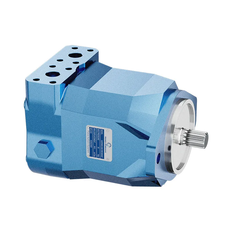
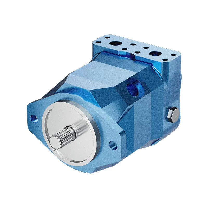


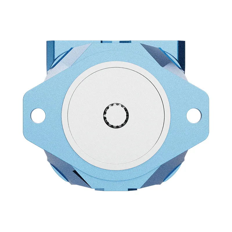
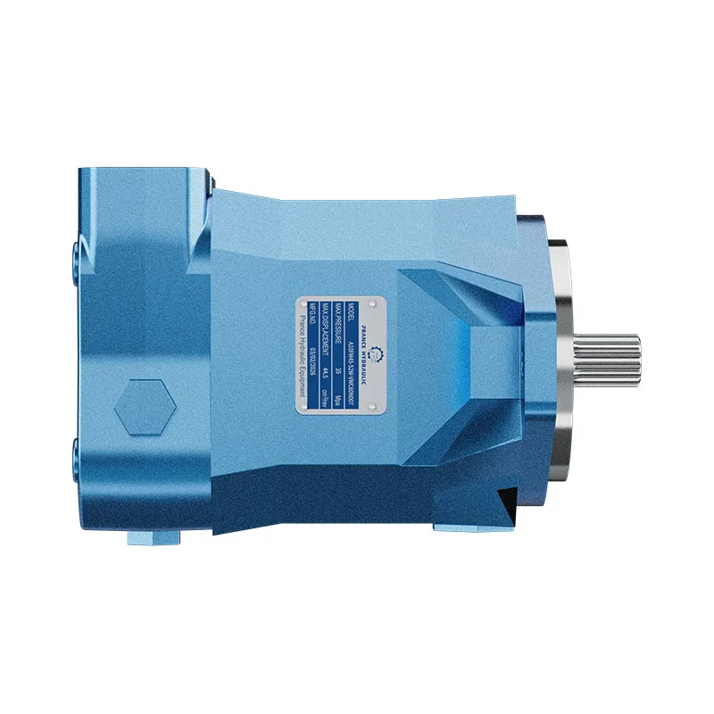
Hydraulic Electro Proportional Control Variable Displacement Piston Motor A10FM
1.Torque increases with pressure gradient between high and low pressure sides
2.Suitable for walking machinery and industrial applications
3.Allows high output speeds
4.Mature A10 rotating component technology
5.Mechanical and hydraulic connections comply with SAE standards
6.Optional built-in anti-cavitation valve, that is, fan drive unit
Descripción detallada
This motor has a clear torque variation rule: its torque increases with the pressure gradient between the high and low pressure sides. The larger the pressure difference between the two sides, the greater the output torque, which ensures that the motor can provide sufficient power to drive heavy loads stably, even in high-pressure working scenarios, avoiding stalling or performance degradation. It is widely suitable for walking machinery and industrial applications, including construction machinery, agricultural equipment, and industrial hydraulic stations, adapting well to the harsh working environment of walking machinery and the stable operation requirements of industrial equipment. The motor allows high output speeds, enabling efficient power transmission and meeting the needs of high-speed operation scenarios, while maintaining stable performance without excessive vibration or noise. It adopts mature A10 rotating component technology, which has undergone long-term practical verification, featuring high reliability, low wear, and stable operation, effectively reducing failure rates and extending the motor’s service life. Its mechanical and hydraulic connections comply with SAE standards, ensuring good compatibility and interchangeability, facilitating installation, maintenance, and replacement with other standard components. Additionally, it is optionally equipped with a built-in anti-cavitation valve, which also serves as a fan drive unit, effectively preventing cavitation damage to the motor and ensuring the normal operation of the fan system, enhancing the overall reliability of the equipment.
Selección y solicitud de cotización
This motor series should be selected from the required torque, speed and duty cycle. Confirm displacement, working pressure, case-drain arrangement where applicable, mounting interface and fluid conditions before final selection.
Información que debe incluir en su RFQ
- Required torque and speed at working pressure
- Preferred displacement or calculated displacement
- Mounting flange, shaft and port orientation
- Duty cycle, fluid, temperature and operating environment
Recursos relacionados
Ordering code for standard program
| A10F | M | / | 52 | - | V | C | ||||||
| 01 | 02 | 03 | 04 | 05 | 06 | 07 | 08 | 09 | 10 | 11 |
Unidad de pistones axiales
| 01 | Swashplate design, fixed displacement, nominal pressure 280 bar, maximum pressure 350 bar | A10F |
Modo de operación
| 02 | Motor, open and closed circuit | M |
Tamaño (NG)
| 03 | Theoretical displacement | 018 | 023 | 028 | 037 | 045 | 058 | 063 |
Series
| 04 | Series 5, Index 2 | 52 |
Sentido de giro
| 05 | Visto en el árbol de transmisión | en el sentido de las agujas del reloj | R1) |
| counter clockwise | L1) | ||
| bidirectional | W |
Focas
| 06 | FKM (Fluoro-rubber) | V |
Árbol de transmisión
| 018 | 023 | 028 | 037 | 045 | 058 | 063 | |||||
| 07 | Splined shaft to ISO 3019-1 (SAE J744) | ○ | ● | ● | ● | ● | ● | ● | R | ||
| Splined shaft to ISO 3019-1 (SAE J744) | – | ○ | ○ | ● | ● | ● | ● | W | |||
| Tapered with woodruff key and threaded end | ○ | ● | ● | ● | ● | ● | ● | C | |||
Brida de montaje
| 018 | 023 | 028 | 037 | 045 | 058 | 063 | |||
| 08 | SAE 2-hole | ○ | ● | ● | ● | ● | ● | ● | C |
Ports for service lines
| 018 | 023 | 028 | 037 | 045 | 058 | 063 | |||
| 09 | SAE-flange ports A and B on side, same side Mounting bolts metric | - | ● | ● | ● | ● | ● | ● | 10N00 |
| Threaded ports A and B,metric, on side, same side | ○ | ● | ● | ● | ● | ● | ● | 16N00 | |
Ventile
| 018 | 023 | 028 | 037 | 045 | 058 | 063 | |||
| 10 | Without valves | ○ | ● | ● | ● | ● | ● | ● | 0 |
| With integrated flushing valve | - | ● | ● | ● | ● | ● | ● | 7 | |
| With integrated anti cavitation valve | ○ | ● | ● | ● | ● | ● | ● | 2 | |
Speed sensor
| 018 | 023 | 028 | 037 | 045 | 058 | 063 | |||
| 11 | Without speed sensor | ○ | ● | ● | ● | ● | ● | ● | |
| Prepared for speed sensor (for inductive speed sensor ID) | ○ | ● | ● | ● | ● | ○ | ○ | D | |
•=available ○=on request — =not available
1)Only necessary in conjunction with valve configuration "2" (integrated anti cavitation valve)
| A10F | E | / | 52 | - | V | |||||||
| 01 | 02 | 03 | 04 | 05 | 06 | 07 | 08 | 09 | 10 | 11 |
Unidad de pistones axiales
| 01 | Swashplate design, fixed displacement, nominal pressure 280 bar, maximum pressure 350 bar | A10F |
Modo de operación
| 02 | Motor, open and closed circuit | E |
Tamaño (NG)
| 03 | Theoretical displacement | 010 | 011 | 014 | 016 | 018 | 023 | 028 | 037 | 045 | 058 | 063 |
Series
| 04 | Series 5, Index 2 | 52 |
Sentido de giro
| 05 | Visto en el árbol de transmisión | en el sentido de las agujas del reloj | R1) |
| counter clockwise | L1) | ||
| bidirectional | W |
Focas
| 06 | FKM (Fluoro-rubber) | V |
Árbol de transmisión
| 010 | 011 | 014 | 016 | 018 | 023 | 028 | 037 | 045 | 058 | 063 | |||||
| 07 | Splined shaft to ISO 3019-1 (SAE J744) | ○ | ● | ● | ● | ● | ● | ● | ● | ● | ● | ● | R | ||
| Splined shaft to ISO 3019-1 (SAE J744) | – | – | – | – | – | ● | ● | ● | ● | ● | ● | W | |||
| Tapered with woodruff key and threaded end | ● | ● | ● | ● | ● | ● | ● | ● | ● | ● | ● | C | |||
Brida de montaje
| 010 | 011 | 014 | 016 | 018 | 023 | 028 | 037 | 045 | 058 | 063 | |||
| 08 | SAE 2-hole | ● | ● | ● | ● | ● | - | - | - | - | - | - | C2) |
| Special 2-hole | - | - | - | - | - | ● | ● | ● | ● | ● | ● | F | |
| Special 8-hole | - | ● | ● | ● | ● | - | - | - | - | - | - | H | |
Ports for service lines
| 010 | 011 | 014 | 016 | 018 | 023 | 028 | 037 | 045 | 058 | 063 | |||
| 09 | SAE-flange ports A and B, on side, same side mounting bolts metric | - | - | - | - | - | ● | ● | ● | ● | ● | ● | 10N00 |
| Threaded ports A and B,metric, on side, same side | ● | ● | ● | ● | ● | ● | ● | ● | ● | ● | ● | 16N00 | |
Ventile
| 010 | 011 | 014 | 016 | 018 | 023 | 028 | 037 | 045 | 058 | 063 | |||
| 10 | Without valves | ○ | ● | ○ | ● | ● | ● | ● | ● | ● | ● | ● | 0 |
| With integrated flushing valve | - | - | - | - | - | ● | ● | ● | ● | ● | ● | 7 | |
| With integrated anti cavitation valve | ● | ● | ● | ● | ● | ● | ● | ● | ● | ● | ● | 2 | |
Speed sensor
| 010 | 011 | 014 | 016 | 018 | 023 | 028 | 037 | 045 | 058 | 063 | |||
| 11 | Without speed sensor | ● | ● | ● | ● | ● | ● | ● | ● | ● | ● | ● | |
| Prepared for speed sensor (for inductive speed sensor ID) | – | – | – | – | ○ | ● | ● | ● | ● | ○ | ○ | D | |
•=available ○=on request — =not available
1)Only necessary in conjunction with valve configuration "2" (integrated anti cavitation valve)
2)R-shaft with C-flange on sizes 10 to 18 in preparation
Datos técnicos
Fluids
Prior to project design, please see our technical data sheets RE 90220 (mineral oil) and RE 90221 (environmentally acceptable fluids) for detailed information on fluids and operating conditions.
For operation on environmentally acceptable fluids please consult us (when ordering, please state in clear text the fluid to be used).
Operating viscosity range
To achieve optimum values for efficiency and service life we recommend an operation viscosity (at operating temperature)within the range,
νelegir = opt. operating viscosity 16...36 mm2/s
referred to the tank temperature (open circuit).
Limit of viscosity range
For critical operation conditions the following values apply:
νmin=5 mm2/s (closed circuit)
10 mm2/s (open circuit)
for short periods (t ≤ 1 min)
at a max. perm. temperature of 115 ℃.
Please note that the max. leakage fluid temperature of 115 ℃ is also not exceeded in certain areas (for instance bearing area).The fluid temperature in the bearing area is approx.5 K higher than the average leakage fluid temperature
νmáx=1600 mm2/s
for short periods (t≤1 min)
on cold start
(tmin =p≤ 30 bar, n ≤ 1000 min-1,-25 °C).
At temperatures between -40℃ and -25℃ special measures are required, please consult us for further information.For detailed information on operation with low temperatures see data sheet RE 90300-03-B.
Selection diagram
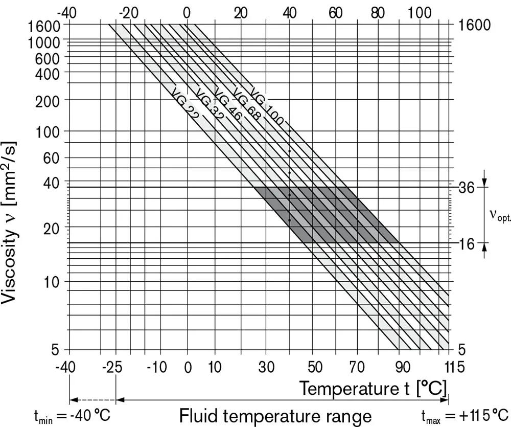
Notes on the selection of the hydraulic fluid
In order to select the correct fluid, it is necessary to know the operating temperature in the tank (open circuit) in relation to the ambient temperature.
The fluid should be selected so that within the operating temperature range, the viscosity lies within the optimum range (νelegir),see shaded section of the selection diagram. We recommend to select the higher viscosity grade in each case.
Example: at an ambient temperature of X℃ the operating temperature in the tank is 60℃. In the optimum viscosity range(νelegir; shaded area) this corresponds to viscosity grades VG 46 resp. VG 68; VG 68 should be selected.
Important:
The leakage oil (case drain oil) temperature is influenced by pressure and input speed and is always higher than the tank temperature. However, at no point of the component may the temperature exceed 115℃.
If it is not possible to comply with the above conditions because of extreme operating parameters please consult us.
Filtration of the hydraulic fluid
Filtration improves the cleanliness level of the hydraulic fluid,which, in turn, increases the service life of the axial piston unit.
To ensure the functional reliability of the axial piston unit, a gravimetric evaluation is necessary for the hydraulic fluid to determine the amount of contamination by solid matter and to determine the cleanliness level according to ISO 4406.A cleanliness level of at least 20/18/15 to ISO 4406 is to be maintained.
If above requirements cannot be maintained please consult us.
Operating pressure range
Pressure at service line port (pressure port) A or B
| Presión nominal PNombre | 280 bar absolute |
| Maximum pressure Pmáx | 350 bar absolute |
| Single operating period | 2,5 ms |
| Total operating period | 300 h |
| Minimum pressure (high pressure side) | 10 bar2) |
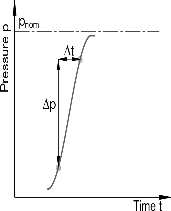
| Rate of pressure change RA max | 16000 bar/s |
Presión de salida
| at nmáx | |
| Minimum pressure at low pressure side Pabs max | 18 bar |
Presión de drenaje de la caja
Maximum permissible case drain pressure
(at port L, L1):
| Pmax abs motor operation in open circuit | 4 bar abdominales |
| Pmax abs motor operation in closed circuit | 4 bar abdominales |
| Pmax abs pump/motor operation in open circuit | 2 bar abdominales |
Direction of flow
| viewed on drive shaft | |||||
| clockwise rotation | counter clockwise rotation | ||||
| A to B | B to A | ||||
Definitions
Presión nominal PNombre
The nominal pressure corresponds to the maximum design
pressure.
Maximum pressure Pmáx
The maximum pressure corresponds to the maximum operating pressure within the single operating period. The sum of the single operating periods must not exceed the total operating period.
Minimum pressure (high-pressure side)
Minimum pressure at the high pressure side (A or B) which is required in order to prevent damage to the axial piston unit.
Rate of pressure change RA
Maximum permissible rate of pressure rise and pressure reduction during a pressure change, over the entire pressure range.
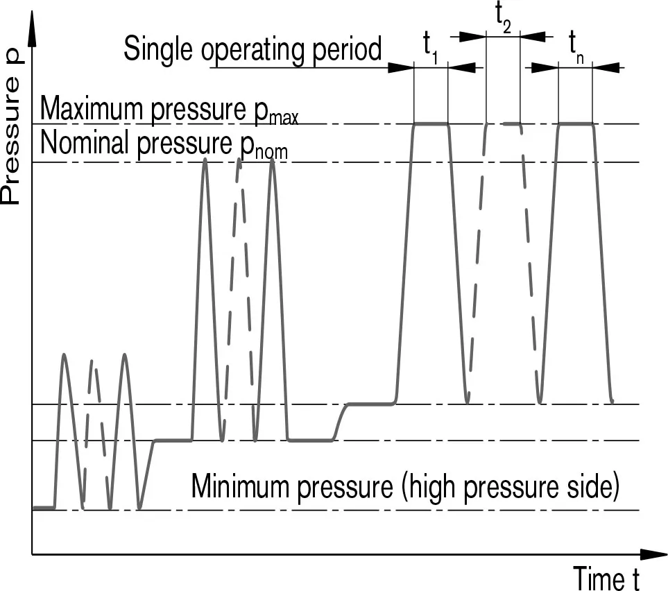
Total operating period =t1 + t2 +... + tn
1)Other values on request
2)Lower pressures time dependent, please consult us.
Table of values (theoretical values, without efficiency and tolerances: value rounded)
| Tamaño | NG | 010 | 011 | 014 | 016 | 018 | 023 | ||
| Desplazamiento | VG máximo | cm3 | 10.6 | 11.5 | 14.1 | 16.1 | 18 | 23.5 | |
| Speed1) | 5000 | 4200 | 4200 | 4200 | 4200 | 4900 | |||
| at VG máximo | nNombre | rpm | |||||||
| Input flow | 53 | 48 | 59 | 68 | 76 | 115 | |||
| at nNombre | qv max | L/min | |||||||
| Poder | 24.7 | 22.5 | 27.6 | 31.6 | 35.3 | 53.6 | |||
| at nNombre, Δp= 280 bar | P máx | kW | |||||||
| Actual starting torque | 37.5 | 30 | 45 | 53 | 67.5 | 75 | |||
| at n= 0 rpm, Δp = 280 bar | Nm | ||||||||
| Par de torsión | 47 | 51 | 63 | 72 | 80 | 105 | |||
| at VG máximo | Δp = 280 bar | Tmáx | Nm | ||||||
| Torsional stiffness | R | c | Nm/rad | - | - | - | - | 14835 | 28478 |
| Árbol de transmisión | W | c | Nm/rad | - | - | - | - | - | - |
| C | c | Nm/rad | 15084 | 18662 | 18662 | 18662 | 18662 | 30017 | |
| Moment of inertia rotary group | JTW | kgm2 | 0.0006 | 0.00093 | 0.00093 | 0.00093 | 0.00093 | 0.0017 | |
| Aceleración angular máxima | α | rad/s2 | 8000 | 6800 | 6800 | 6800 | 6800 | 5500 | |
| Volumen de casos | V | L | 0.1 | 0.15 | 0.15 | 0.15 | 0.15 | 0.6 | |
| Weight approx. | m | kg | 5 | 6.5 | 6.5 | 6.5 | 6.5 | 12 | |
| Tamaño | NG | 028 | 037 | 045 | 058 | 063 | ||
| Desplazamiento | VG máximo | cm3 | 28.5 | 11.5 | 14.1 | 16.1 | 18 | |
| Speed1) | ||||||||
| at VG máximo | nNombre | rpm | 4700 | 4200 | 4000 | 3600 | 3400 | |
| Input flow | 134 | 154 | 178 | 209 | 215 | |||
| at nNombre | qv max | L/min | ||||||
| Poder | 62.5 | 71.8 | 83.1 | 97.4 | 100.1 | |||
| at nNombre, Δp= 280 bar | P máx | kW | ||||||
| Actual starting torque | 105 | 125 | 170 | 205 | 230 | |||
| at n= 0 min-1, Δp = 280 bar | Nm | |||||||
| Par de torsión | 127 | 163 | 198 | 258 | 281 | |||
| at VG máximo | Δp = 280 bar | Tmáx | Nm | |||||
| Torsional stiffness | R | c | Nm/rad | 28478 | 46859 | 46859 | 80590 | 80590 |
| Árbol de transmisión | W | c | Nm/rad | - | 38489 | 38489 | 60907 | 60907 |
| C | c | Nm/rad | 30017 | 46546 | 46546 | 87667 | 87667 | |
| Moment of inertia rotary group | JTW | kgm2 | 0.0017 | 0.0033 | 0.0033 | 0.0056 | 0.0056 | |
| Aceleración angular máxima | α | rad/s2 | 5500 | 4000 | 4000 | 3300 | 3300 | |
| Volumen de casos | V | L | 0.6 | 0.7 | 0.7 | 0.8 | 0.8 | |
| Weight approx. | m | kg | 12 | 17 | 17 | 22 | 22 | |
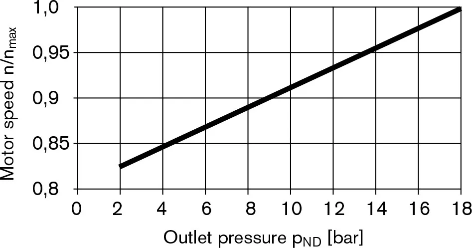
1)for maximum speed an outlet pressure (in low pressure side) of 18 bar is required
Note
Operation above the maximum values or below the minimum values may result in a loss of function, a reduced service life or in the destruction of the axial piston unit We recommend testing the loads by means of experiment or calculation/ simulation and comparison with the permissible values.
Permissible motor speed in relation to outlet pressure
Determination of motor size (NG)
| Input flow | qv=(Vg∙n)/(1000∙ηv) | [L/min] | Vg=Displacement per revolution in cm3 Δp=Differential pressure in bar n=speed in rpm ηv=Volumetric efficiency ηMh=Mechanical-hydraulic efficiency ηt=Overall efficiency (ηt = ηv ∙ηMh) TK=Torque constant |
| Par de torsión | T=(1,59∙Vg∙ Δp∙ηMh)/100 | [Nm] | |
| or | T=Tk∙ Δp∙ηMh | ||
| Poder | P=(2π∙T∙n)/60000=(qv∙Δp∙ηt)/600 | [kW] | |
| Output speed | n=(qv∙1000∙ηv)/Vg | [rpm] | |
Permissible radial and axial forces on the drive shaft
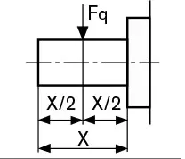
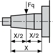
| Max. radial force at X/2 | Drive shaft R; W | Drive shaft C | Fq max | N | 250 | 350 | 350 | 350 | 350 | 1200 |
 |
 |
|||||||||
| Maximum axial force | 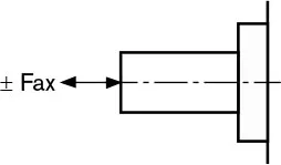 |
± Fax max | N | 400 | 700 | 700 | 700 | 700 | 1000 |
| Tamaño | NG | 28 | 37 | 45 | 58 | 63 | |||
| Max. radial force at X/2 | Drive shaft R; W | Drive shaft C | Fq max | N | 1200 | 1500 | 1500 | 1700 | 1700 |
|
|
||||||||
| Maximum axial force | |
± Fax max | N | 1000 | 1500 | 1500 | 2000 | 2000 | |
