Wenzhou Prance Hydraulic Equipment Co., Ltd


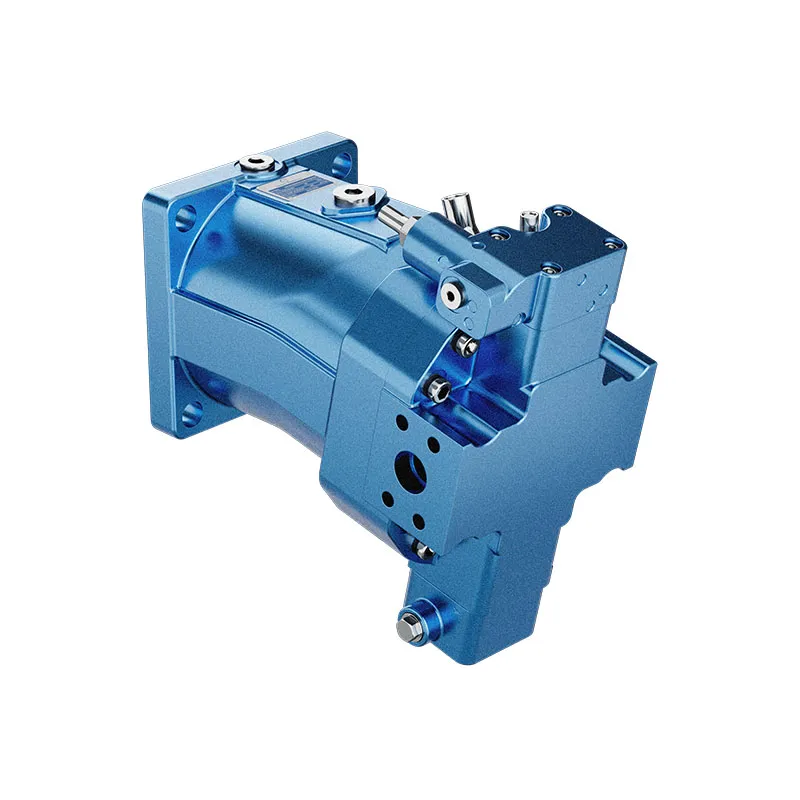
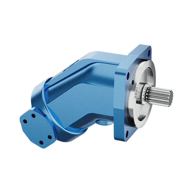
AA6VM Variable Displacement Bent Axis Motor
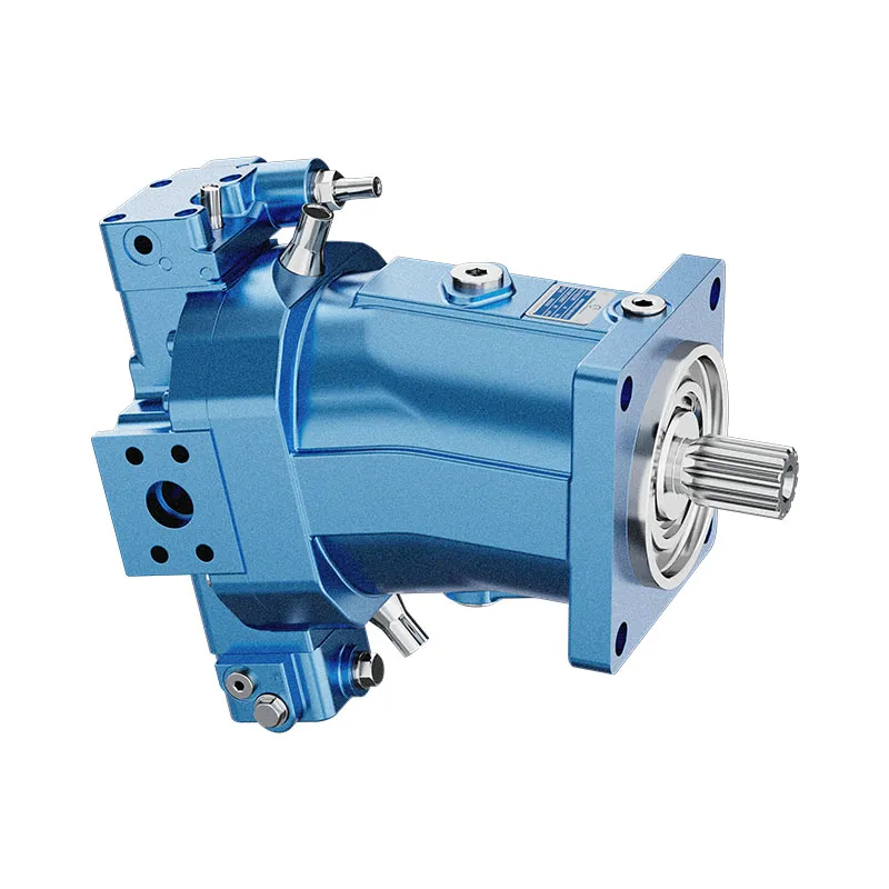
The AA6VM variable displacement bent-axis motor changes the torque-speed relationship by changing displacement. The technical table covers nominal size 250; it is not a complete rating table for all AA6VM sizes.
- Variable bent-axis motor
- Displacement-control options
- Flushing and boost valve options
- Counterbalance arrangement requires confirmation
PRANCE HYDRAULIC · PRODUCT SERIES
AA6VM Variable Displacement Bent Axis Motor
Axial piston; bent axis, variable displacement · Confirm open or closed circuit configuration
The AA6VM variable displacement bent-axis motor changes the torque-speed relationship by changing displacement. The technical table covers nominal size 250; it is not a complete rating table for all AA6VM sizes.
Model
✓
Request a QuotationView Technical Data & DatasheetAA6VMAxial piston; bent axis, variable displacement
Confirm the complete model and approved specification with Prance Hydraulic. Product-series references alone do not establish interchangeability.
Configuration review · Technical documentation · Product selection
Product Details
- Variable bent-axis motor
- Displacement-control options
- Flushing and boost valve options
- Counterbalance arrangement requires confirmation
CATEGORIES: Piston Motor, Variable Displacement Piston Motor
AA6VM Features & Application
Variable bent-axis motor
Specify the displacement range or switching arrangement and verify performance at each required setting.
Displacement-control options
Match the complete control option and its command requirements to the existing controller. Similar housings can use different control arrangements.
Flushing and boost valve options
Account for pilot or replenishment demand and the relevant pressure limits. Include filtration and the return or drain route in the circuit review.
Counterbalance arrangement requires confirmation
Specify the full AA6VM order code, installation drawing and operating duty so the quotation can identify the proposed configuration.
AA6VM Specifications
| Series / model | AA6VM |
|---|---|
| Product type | AA6VM Variable Displacement Bent Axis Motor |
| Design | Axial piston; bent axis, variable displacement |
| Circuit / selection | Confirm open or closed circuit configuration |
| Technical table scope | Nominal size 250 |
| Listed maximum displacement | 250 cm³/rev |
| Minimum displacement and controls | Confirm the selected setting and full model code |
AA6VM Selection & Configuration
The AA6VM variable displacement bent-axis motor changes the torque-speed relationship by changing displacement. The technical table covers nominal size 250; it is not a complete rating table for all AA6VM sizes.
Specify the maximum and minimum displacement settings, control mode and response on loss of command. A small displacement increases speed for a given flow but reduces torque at the same pressure difference. Check flushing, replenishment and braking requirements for the circuit.
Your Application.
The Right Configuration.
Hydraulic pumps · Hydraulic motors · Hydraulic valves
Send the AA6VM nameplate, operating requirements and installation drawing for a configuration review before quoting.
- Model review — send the full model code or an existing nameplate photograph.
- Interface matching — confirm shaft, mounting flange, rotation and ports.
- Operating conditions — provide flow, pressure, speed, fluid and duty cycle.
- Documentation — request the relevant product data and drawings for your review.

AA6VM Buying Guide
Use this sequence to prepare the AA6VM configuration for review and quotation.
- Define starting and continuous torque, speed range and duty cycle.
- Specify available flow, work-port pressure difference and return pressure.
- Confirm the displacement setting and required behavior during starting and stopping.
- Check shaft, mounting pilot, flange, port orientation and external loads.
- Review case drainage, replenishment and any displacement control.
- Specify fluid conditions and any independent braking requirement.
- Approve the complete model, operating envelope, drawing and quantity.
Selection, Documentation & Project Support

Selection Support
Learn more →Share your hydraulic circuit, operating point and installation requirements for a configuration discussion.
Flow · Pressure · Speed · Interfaces

Technical Resources
Learn more →Review product documentation, model codes and technical data before finalizing the specification.
Datasheets · Model codes · Drawings

Project Inquiries
Learn more →Send your required model, quantity, application and project requirements to discuss your inquiry.
Product inquiries · Configuration review
Configuration, Quantity & Delivery
Confirm the complete AA6VM code, approved drawing and operating limits. Availability, quantity, documentation and delivery date are confirmed in the quotation.
Discuss Your AA6VM Application
Send the full model code, operating duty, installation details and quantity.
Request a AA6VM QuotationAA6VM Questions Before Ordering
What type of product is the AA6VM?
AA6VM Variable Displacement Bent Axis Motor. Design: Axial piston; bent axis, variable displacement. Confirm open or closed circuit configuration. Confirm the complete order code for the offered version.
Can a similar motor replace the AA6VM?
Only after checking the operating duty, interfaces and control requirements. A matching displacement, nominal size or photograph does not establish interchangeability. Compare the approved drawings and complete codes.
Which data is needed for a quotation?
Define starting and continuous torque, speed range and duty cycle. Specify available flow, work-port pressure difference and return pressure. Attach the nameplate, complete order code, installation drawing and required quantity.
AA6VM Technical Data & Documents
View AA6VM catalog data and operating conditions
Catalog reference for the model rows and variants explicitly identified below. Keep each value with its unit, duty condition and footnotes. Family tables may include related versions; confirm the complete offered code and approved data before ordering.
Technical data
| Size | NG | 250 | ||
| Displacement geometric, per revolution1) | Vg max | in3 | 15.26 | |
| cm3 | 250 | |||
| Vg min | in3 | 0 | ||
| cm3 | 0 | |||
| Vg x | in3 | 12.51 | ||
| cm3 | 205 | |||
| Maximum rotationalspeed2) (while adhering to the maximum permissible inlet flow) | at Vg max | nnom | rpm | 2700 |
| at Vg<Vgx | nmax | rpm | 3300 | |
| at Vg 0 | nmax | rpm | Please contact us | |
| Inlet flow | at nnom and Vg max | qv max | gpm | 178 |
| l/min | 675 | |||
| Torque3) | at Vg max and Δp = 5800 psi(400 bar) | T | lb-ft | – |
| Nm | – | |||
| at Vg max and Δp = 5100 psi(350 bar) | lb-ft | 1026 | ||
| Nm | 1391 | |||
| Rotary stiffness | Vg max to Vg/2 | Cmin | lb-ft/rad | |
| kNm/rad | 60 | |||
| Vg/2 to 0 (interpolated) | Cmin | lb-ft/rad | ||
| kNm/rad | 181 | |||
| Moment of inertia for rotary group | JTW | lb-ft2 | 1.448 | |
| kgm2 | 0.061 | |||
| Maximum angular acceleration | α | rad/s2 | 10000 | |
| Case volume | V | gal | 0.79 | |
| l | 3.0 | |||
| Weight, approx. | m | lbs | 220 | |
| kg | 100 | |||
Speed range
The minimum rotational speed nmin is not restricted. Please consult us regarding applications requiring uniformity of the rotatory motion at low speeds. ▼Permissible displacement in relation to speed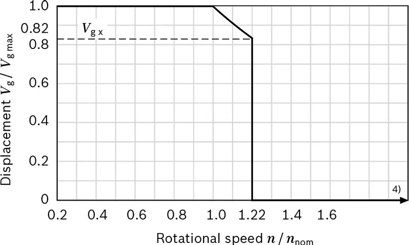
Notes
▶Theoretical values, without efficiency and tolerances;values rounded ▶Operation above the maximum values or below the minimum values may result in a loss of function, a reduced service life or in the destruction of the axial piston unit. Other permissible limit values, such as speed variation, reduced angular acceleration as a function of the frequency and the permissible angular acceleration at start (lower than the maximum angular acceleration) can be found in data sheet 90261.Determining the operating characteristics
| Inlet flow | qv=(Vg×n)/(231×ηv) | [gpm] | ((Vg×n)/(1000×ηv)) | [l/min] |
| Rotational speed | n=(qv×231×ηv)/Vg | [rpm] | ((qv×1000×ηv)/Vg) | [rpm] |
| Torque | T=(Vg×Δp×ηmh)/(24×π) | [lb-ft] | ((Vg×Δp×ηmh)/(20×π)) | [Nm] |
| Power | P=(2π×T×n)/33000=(qv×Δp×ηt)/1714 | [HP] | ((2π×T×n)/60000=(qv×Δp×ηt)/600) | [kW] |
| Key Vg=Displacement per revolution [in3 (cm3)] Δp=Differential pressure [psi (bar)] n=Rotational speed [rpm] ηv=Volumetric efficiencyI ηmh=Mechanical-hydraulic efficiency ηt=Total efficiency (nt=ny·nmh) | ||||
Permissible radial and axial forces of the drive shafts
| Size | NG | 250 | ||
| Drive shaft | DIA | in | 2 | |
| Maximum radial force at distance a (from shaft collar) | 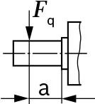 |
Fq max | lb | 2701) |
| N | 12001) | |||
| a | in | 1.32 | ||
| mm | 33.5 | |||
| Maximum torque at Fq max | Tq max | lb-ft | 2) | |
| Nm | 2) | |||
| Maximum differential pressure at Vg max and Fq max | Δpq max | psi | 2) | |
| bar | 2) | |||
| Maximum axial force at standstill or depressurized operation | 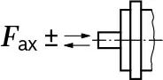 |
+Fax max | lb | 0 |
| N | 0 | |||
| -Fax max | lb | 270 | ||
| N | 1200 | |||
| Permissible axial force per psi (bar) working pressure | +Fax perm/bar | lb/psi | 2) | |
| N/bar | 2) | |||
Notices
▶The values given are maximum values and do not apply to continuous operation. ▶The permissible axial force in -Fax direction is to be avoided, because thereby the bearing life is reduced. ▶Special requirements apply in the case of belt drives.Please contact us. Effect of radial force Fq on the service life of bearings By selecting a suitable direction of radial force Fa, the load on the bearings, caused by the internal rotary group forces can be reduced, thus optimizing the service life of the bearings. Recommended position of mating gear is dependent on direction of rotation. Example: ▼Toothed gear output drive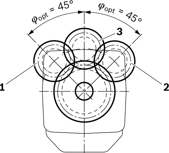 1 Direction of rotation “counter-clockwise”, pressure at port B
2 Direction of rotation “clockwise”, pressure at port A
3 Bidirectional direction of rotation
1) When at standstill or when axial piston unit working in depressurized conditions. Higher forces are permissible under pressure,please contact us.
2) Please contact us.
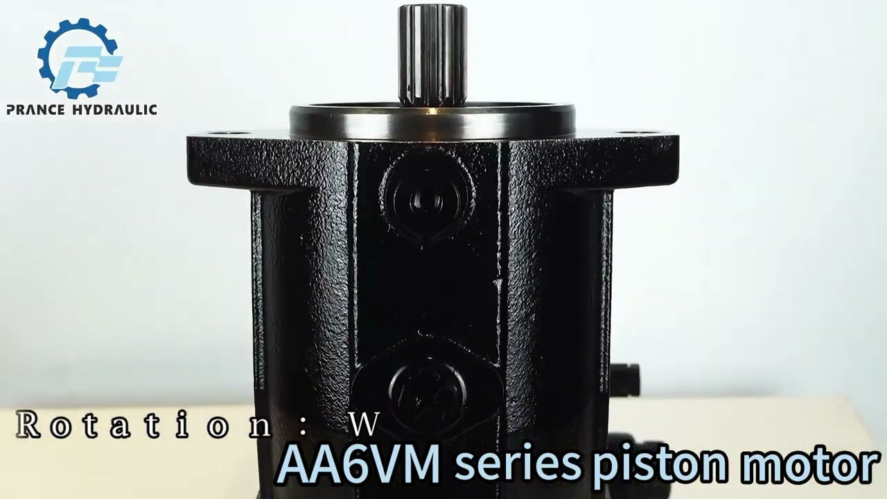
Watch AA6VM Product Video
Related Selection Resources
Request a AA6VM Quotation
Tell us your required configuration, quantity and application.
Related Products
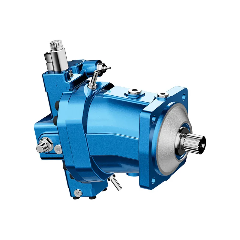
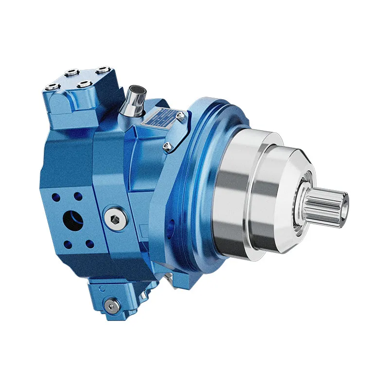
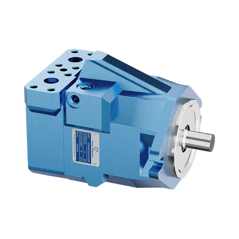
Compare related hydraulic motors and confirm the complete configuration for your application.
Type code
| 01 | 02 | 03 | 04 | 05 | 06 | 07 | 08 | 09 | 10 | 11 | 12 | 13 | 14 | 15 | 16 | 17 | 18 | 19 | 20 | |||
| AA6V | M | 250 | / | 63 | W | - | V | S | D | - |
Hydraulic fluid
| 01 | Mineral oil and HFD. HFD only in combination with long-life bearings "L" (without code) | |
| HFB, HFC hydraulic fluid only in conjunction with long-life bearings “L” | E |
Axial piston unit
| 02 | Bent-axis design, variable, nominal pressure 5100 psi (350 bar), maximum pressure 5800 psi (400 bar) | AA6V |
Drive shaft bearing
| 03 | Standard bearing (without code) | |
| Long-life bearing | L |
Operating mode
| 04 | Motor (plug-in motor A6VE) | M |
size(NG)
| 05 | Geometric displacement | in cm3/rev | 250 |
| in in3/rev | 15.25 |
Control device
| 06 | Proportional control hydraulic | ΔPst= 145 psi (10 bar) | HD1 |
| ΔPst= 365 psi (25 bar) | HD2 | ||
| ΔPst=510 psi (35 bar) | HD3 | ||
| Proportional control electrical1) | U=12 V DC | EP1 | |
| U=24 V DC | EP2 | ||
| Two-point control hydraulic | HZ | ||
| Two-point control electrical1) | U=12 V DC | EZ1 | |
| U=24 V DC | EZ2 | ||
| Automatic control high-pressure related | with minimum pressure increase Δp ≤ approx. 145 psi (10 bar) | HA1 | |
| with pressure increase Δp= 1450 psi (100 bar) | HA2 | ||
| Automatic control speed related pst/ pHD=3/100 | hydraulic travel direction valve | DA |
Pressure control/override (only for HD, EP)
| 07 | Without pressure control/override | ||
| Pressure control fixed setting | fixed setting | D | |
| hydraulic override, two-point | E2) | ||
| hydraulic remote control, proportional | G | ||
Overrides for the HA1 and HA2 controls
| 08 | Without override | |
| Hydraulic override, remonte control, proportinal | T |
Series
| 09 | Series 6, index 3 | 63 |
Direction of rotation
| 10 | Viewed on drive shaft, bidirectional | W |
Setting range for displacement3)
| 11 | Vg min = 0 to 0.4 Vg max Vg max=Vg max to 0.8 Vg max | 1 |
| Vg max > 0.4 Vg max to 0.8 Vg max Vg max=Vg max to 0.8 Vg max | 2 |
•=Available ○=On request -=Not available
1) Hirschmann connector Standard
2) Fitted as standard with version D
3) Please specify exact settings for Vg min and Vg max in plain text when ordering: Vg min = ... in3 (cm3), Vg max = ... in3 (cm3)
Sealing material
| 12 | FKM (fluoroelastomer) | V |
Drive shaft
| 13 | Splined shaft ANSI B92.1a | S |
Mounting flange
| 14 | SAE J744 -4-bolt 165-4 | D |
Working port4)
| 15 | SAE working ports A and B at rear | 51 | 0 | ● | 510 |
| 7 | ● | 517 | |||
| SAE working ports A and B at side, opposite | 52 | 0 | ● | 520 | |
| 7 | ● | 527 |
Valves: 0=Without valve 7=Flushing and boost-pressure valve, mounted
Speed sensor
| 16 | Without speed sensor (without code) | ||
| Prepared for HDD speed sensor | ▲ | F | |
| HDD speed sensor mounted5) | ▲ | H |
Swivel angle sensor
| 17 | Without swivel angle sensor (without code) | |
| Optical swivel angle sensor | V | |
| Electric swivel angle sensor | E |
Beginning of control
| 18 | At Vg min (standard for HA) | A |
| At Vg max (standard for HD, HZ, EP, EZ, DA) | B |
Standard / special version
| 19 | Standard version | 0 |
| Special version | -S |
•=Available ○=On request ▲=Not for new projects -=Not available
Notices
▶Note the project planning notes
▶When ordering, please provide the relevant technical data additionally to the type code.
4) Fastening threads, SAE
5)Specify type code separately for sensor in accordance with data sheet 95135 - HDD and observe the requirements for the electronics.
Technical data
| Size | NG | 250 | ||
| Displacement geometric, per revolution1) | Vg max | in3 | 15.26 | |
| cm3 | 250 | |||
| Vg min | in3 | 0 | ||
| cm3 | 0 | |||
| Vg x | in3 | 12.51 | ||
| cm3 | 205 | |||
| Maximum rotationalspeed2) (while adhering to the maximum permissible inlet flow) | at Vg max | nnom | rpm | 2700 |
| at Vg<Vgx | nmax | rpm | 3300 | |
| at Vg 0 | nmax | rpm | Please contact us | |
| Inlet flow | at nnom and Vg max | qv max | gpm | 178 |
| l/min | 675 | |||
| Torque3) | at Vg max and Δp = 5800 psi(400 bar) | T | lb-ft | - |
| Nm | - | |||
| at Vg max and Δp = 5100 psi(350 bar) | lb-ft | 1026 | ||
| Nm | 1391 | |||
| Rotary stiffness | Vg max to Vg/2 | Cmin | lb-ft/rad | |
| kNm/rad | 60 | |||
| Vg/2 to 0 (interpolated) | Cmin | lb-ft/rad | ||
| kNm/rad | 181 | |||
| Moment of inertia for rotary group | JTW | lb-ft2 | 1.448 | |
| kgm2 | 0.061 | |||
| Maximum angular acceleration | α | rad/s2 | 10000 | |
| Case volume | V | gal | 0.79 | |
| l | 3.0 | |||
| Weight, approx. | m | lbs | 220 | |
| kg | 100 | |||
Speed range
The minimum rotational speed nmin is not restricted. Please consult us regarding applications requiring uniformity of the rotatory motion at low speeds.
▼Permissible displacement in relation to speed
Notes
▶Theoretical values, without efficiency and tolerances;values rounded
▶Operation above the maximum values or below the minimum values may result in a loss of function, a reduced service life or in the destruction of the axial piston unit. Other permissible limit values, such as speed variation, reduced angular acceleration as a function of the frequency and the permissible angular acceleration at start (lower than the maximum angular acceleration) can be found in data sheet 90261.
Determining the operating characteristics
| Inlet flow | qv=(Vg×n)/(231×ηv) | [gpm] | ((Vg×n)/(1000×ηv)) | [l/min] |
| Rotational speed | n=(qv×231×ηv)/Vg | [rpm] | ((qv×1000×ηv)/Vg) | [rpm] |
| Torque | T=(Vg×Δp×ηmh)/(24×π) | [lb-ft] | ((Vg×Δp×ηmh)/(20×π)) | [Nm] |
| Power | P=(2π×T×n)/33000=(qv×Δp×ηt)/1714 | [HP] | ((2π×T×n)/60000=(qv×Δp×ηt)/600) | [kW] |
| Key Vg=Displacement per revolution [in3 (cm3)] Δp=Differential pressure [psi (bar)] n=Rotational speed [rpm] ηv=Volumetric efficiencyI ηmh=Mechanical-hydraulic efficiency ηt=Total efficiency (nt=ny·nmh) |
||||
1)The minimum and maximum displacement can be steplessly adjusted,see type code . (standard setting if ordering code is missing: Vg min = 0.2 × Vg max, Vg max = Vg max).
2) The values are applicable:
- for the optimum viscosity range from νopt = 170 to 75 SUS (36 to 16 mm2/s)
- with hydraulic fluid based on mineral oils
3)Torque without radial force, with radial force.
4) Values in this range on request
Permissible radial and axial forces of the drive shafts
| Size | NG | 250 | ||
| Drive shaft | DIA | in | 2 | |
| Maximum radial force at distance a (from shaft collar) | |
Fq max | lb | 2701) |
| N | 12001) | |||
| a | in | 1.32 | ||
| mm | 33.5 | |||
| Maximum torque at Fq max | Tq max | lb-ft | 2) | |
| Nm | 2) | |||
| Maximum differential pressure at Vg max and Fq max | Δpq max | psi | 2) | |
| bar | 2) | |||
| Maximum axial force at standstill or depressurized operation | |
+Fax max | lb | 0 |
| N | 0 | |||
| -Fax max | lb | 270 | ||
| N | 1200 | |||
| Permissible axial force per psi (bar) working pressure | +Fax perm/bar | lb/psi | 2) | |
| N/bar | 2) | |||
Notices
▶The values given are maximum values and do not apply to continuous operation.
▶The permissible axial force in -Fax direction is to be avoided, because thereby the bearing life is reduced.
▶Special requirements apply in the case of belt drives.Please contact us.
Effect of radial force Fq on the service life of bearings
By selecting a suitable direction of radial force Fa, the load on the bearings, caused by the internal rotary group forces can be reduced, thus optimizing the service life of the bearings. Recommended position of mating gear is dependent on direction of rotation. Example:
▼Toothed gear output drive
1 Direction of rotation "counter-clockwise", pressure at port B
2 Direction of rotation "clockwise", pressure at port A
3 Bidirectional direction of rotation
1) When at standstill or when axial piston unit working in depressurized conditions. Higher forces are permissible under pressure,please contact us.
2) Please contact us.
