Wenzhou Prance Hydraulic Equipment Co., Ltd


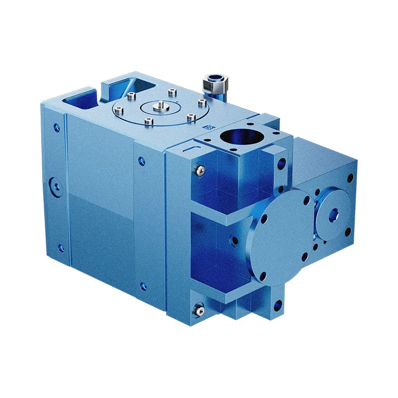

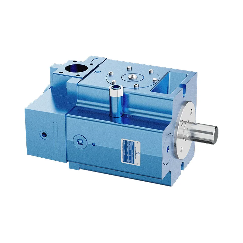
PVXS Swashplate Variable Displacement Piston Pump
The PVXS variable displacement pump uses a swashplate axial piston design, as stated in the existing technical table. It should not be described as a bent-axis pump. The published model groups are 66, 90, 130, 180 and 250.
- Swashplate axial piston design
- Model sizes 66, 90, 130, 180 and 250
- Flange or foot mounting listed
- Tandem arrangement requires mounting and torque review
PRANCE HYDRAULIC · PRODUCT SERIES
PVXS Swashplate Variable Displacement Piston Pump
Axial piston; swashplate · Confirm the selected industrial circuit
The PVXS variable displacement pump uses a swashplate axial piston design, as stated in the existing technical table. It should not be described as a bent-axis pump. The published model groups are 66, 90, 130, 180 and 250.
Model
✓
Request a QuotationVer Dados Técnicos e Folha de DadosPVXSAxial piston; swashplate
Confirm the complete model and approved specification with Prance Hydraulic. Product-series references alone do not establish interchangeability.
Configuration review · Technical documentation · Product selection
Detalhes do Produto
- Swashplate axial piston design
- Model sizes 66, 90, 130, 180 and 250
- Flange or foot mounting listed
- Tandem arrangement requires mounting and torque review
CATEGORIES: Bomba de caudal variável, Bomba de pistão
PVXS Features & Application
Swashplate axial piston design
Specify the full MS order code, installation drawing and operating duty so the quotation can identify the proposed configuration.
Model sizes 66, 90, 130, 180 and 250
Include the series and all order-code suffixes in the enquiry. A common nominal size does not establish compatibility.
Flange or foot mounting listed
Check pilot diameter, bolt pattern, shaft engagement or port pattern against the approved installation drawing.
Tandem arrangement requires mounting and torque review
Check pilot diameter, bolt pattern, shaft engagement or port pattern against the approved installation drawing.
PVXS Specifications
| Series / model | PVXS |
|---|---|
| Product type | PVXS Swashplate Variable Displacement Piston Pump |
| Design | Axial piston; swashplate |
| Circuit / selection | Confirm the selected industrial circuit |
| Published model sizes | 66, 90, 130, 180 and 250 |
| Pressão nominal | 350 bar at 100% duty in the existing table |
| Pressão máxima | 420 bar; confirm permitted operating conditions |
| Published speed range | 150–1800 rpm; review the selected operating point |
PVXS Selection & Configuration
The PVXS variable displacement pump uses a swashplate axial piston design, as stated in the existing technical table. It should not be described as a bent-axis pump. The published model groups are 66, 90, 130, 180 and 250.
For an industrial drive, distinguish nominal pressure from the maximum pressure and check the speed range at the required displacement. Tandem mounting also changes the installation and drive-torque review. Confirm the selected control, suction pressure and case-pressure allowance.

cURL Too many subrequests by single Worker invocation. To configure this limit, refer to https://developers.cloudflare.com/workers/wrangler/configuration/#limits.
cURL Too many subrequests by single Worker invocation. To configure this limit, refer to https://developers.cloudflare.com/workers/wrangler/configuration/#limits.
Hydraulic pumps · Hydraulic motors · Hydraulic valves
Send the MS nameplate, operating requirements and installation drawing for a configuration review before quoting.
- Model review — send the full model code or an existing nameplate photograph.
- Interface matching — confirm shaft, mounting flange, rotation and ports.
- Operating conditions — provide flow, pressure, speed, fluid and duty cycle.
- Documentation — request the relevant product data and drawings for your review.

PVXS Buying Guide
Use this sequence to prepare the MS configuration for review and quotation.
- Define required flow at the actual drive speed and continuous pressure.
- Identify peak pressure, duration and the work cycle.
- Confirm the selected displacement control and any auxiliary-drive requirement.
- Match rotation viewed from the shaft end, shaft, flange and ports.
- Review inlet conditions, drain routing and the installation envelope.
- Confirm fluid, viscosity, temperature, filtration and seals.
- Approve the complete model, control, drawing, quantity and delivery terms.

Selection, Documentation & Project Support

Selection Support
Learn more →Share your hydraulic circuit, operating point and installation requirements for a configuration discussion.
Flow · Pressure · Speed · Interfaces

Technical Resources
Learn more →Review product documentation, model codes and technical data before finalizing the specification.
Datasheets · Model codes · Drawings

Project Inquiries
Learn more →Send your required model, quantity, application and project requirements to discuss your inquiry.
Product inquiries · Configuration review
Configuration, Quantity & Delivery
Confirm the complete MS code, approved drawing and operating limits. Availability, quantity, documentation and delivery date are confirmed in the quotation.
Discuss Your PVXS Application
Send the full model code, operating duty, installation details and quantity.
Request a PVXS QuotationPVXS Questions Before Ordering
What type of product is the PVXS?
PVXS Swashplate Variable Displacement Piston Pump. Design: Axial piston; swashplate. Confirm the selected industrial circuit. Confirm the complete order code for the offered version.
Can a similar pump replace the PVXS?
cURL Too many subrequests by single Worker invocation. To configure this limit, refer to https://developers.cloudflare.com/workers/wrangler/configuration/#limits.
cURL Too many subrequests by single Worker invocation. To configure this limit, refer to https://developers.cloudflare.com/workers/wrangler/configuration/#limits
Define required flow at the actual drive speed and continuous pressure. Identify peak pressure, duration and the work cycle. Attach the nameplate, complete order code, installation drawing and required quantity.
PVXS Technical Data & Documents
View PVXS catalog data and operating conditions
cURL Too many subrequests by single Worker invocation. To configure this limit, refer to https://developers.cloudflare.com/workers/wrangler/configuration/#limits.
Dados Técnicos
| MODELO | 66 | 90 | 130 | 180 | 250 | ||
| Design | Swashplate – Axial piston pump | ||||||
| Tipo de montagem | Montagem com flange ou com pés. O modelo «tandem» é montado apenas com pés. | ||||||
| Ligação de tubagem Flange SAE | B | psi | 1 1/2″=3000 | 2″=3000 | 2 1/2″=3000 | 2 1/2″=3000 | 3 1/2″=500 |
| A | 1″=6000 | 1″=6000 | 1″=6000 | 1 1/4″=6000 | 1 1/4″=6000 | ||
| Sentido de rotação | Clockwise when viewing shaft end of pump Counterclockwise available on request | ||||||
| Gama de velocidades | nmin | rpm | 150 | ||||
| nmáx | 1800 | ||||||
| Posição de instalação | Opcional, ver informação de montagem | ||||||
| Gama de temperaturas ambiente | min | ℉ | -4 | ||||
| máx | 122 | ||||||
| Peso | m | lb | 121 | 165 | 234 | 251 | 467 |
| Momento de inércia | J | livre pé2 | 0.38 | 0.38 | 1.068 | 1.068 | 3.465 |
HIDRÁULICO CARATERÍSTICAS
| Fluido hidráulico | Óleo hidráulico conforme a norma DIN 51524, parte 2. Consulte a secção «Dados de aplicação — Recomendações relativas aos fluidos» | |||||||
| Gama de temperaturas do fluido hidráulico | min | ℉ | -13 (no arranque) | |||||
| máx | 194 | |||||||
| Gama de viscosidade para funcionamento contínuo | min | CST | 10 | |||||
| máx | CST | 75 | ||||||
| Viscosidade máxima admissível no arranque | máx | CST | 1000 | |||||
| Filtragem | ISO 4406 | 18/15/13 | ||||||
| Geometria máxima | n=1500rpm | Vg | em3 | 4.1 | 5.5 | 7.9 | 11 | 15.2 |
| deslocamento | n=1800rpm | |||||||
| Geometria máxima | n=1500rpm | Qg | EUAboa tarde | 26 | 36 | 52 | 71 | 99 |
| caudal da bomba | n=1800rpm | 32 | 43 | 62 | 86 | 119 | ||
| Pressão da caixa | pv máx | psi | máx. 7,2 psi acima de p1. Pmáx = 58 abs. | |||||
Conduzir
| Maximum driving torque – single unit (p2 máx. ,η = 100%) | M1 Individual | lb.ft | 325 | 444 | 640 | 887 | 1233 |
| Maximum power consumption – single unit (p2 máx., η = 1001 TP³T; n = 1800 rpm) | P1 Individual | HP | 93 | 126 | 182 | 254 | 355 |
| Maximum driving torque limited to splined shaft only – comb. unit | M1 Comb. | lb.ft | 2×325 | 2×444 | cURL Too many subrequests by single Worker invocation. To configure this limit, refer to https://developers.cloudflare.com/workers/wrangler/configuration/#limits | cURL Too many subrequests by single Worker invocation. To configure this limit, refer to https://developers.cloudflare.com/workers/wrangler/configuration/#limits | cURL Too many subrequests by single Worker invocation. To configure this limit, refer to https://developers.cloudflare.com/workers/wrangler/configuration/#limits |
| MODELO | 66 | 90 | 130 | 180 | 250 | ||
| Design | Swashplate – Axial piston pump | ||||||
| Tipo de montagem | Montagem com flange ou com pés. O modelo «tandem» é montado apenas com pés. | ||||||
| Ligação de tubagem Flange SAE | B | psi | 1 1/2″=3000 | 2″=3000 | 2 1/2″=3000 | 2 1/2″=3000 | 3 1/2″=500 |
| A | 1″=6000 | 1″=6000 | 1″=6000 | 1 1/4″=6000 | 1 1/4″=6000 | ||
| Sentido de rotação | Clockwise when viewing shaft end of pump Counterclockwise available on request | ||||||
| Gama de velocidades | nmin | min-1 | 150 | ||||
| nmáx | 1800 | ||||||
| Posição de instalação | Opcional, ver informação de montagem | ||||||
| Gama de temperaturas ambiente | min | ℃ | -20 | ||||
| máx | 50 | ||||||
| Peso | m | kg | 55 | 75 | 106 | 114 | 212 |
| Momento de inércia | J | kg m2 | 0.016 | 0.016 | 0.045 | 0.045 | 0.146 |
CARATERÍSTICAS HIDRÁULICAS
| Pressão nominal (ciclo de funcionamento 100%) | PN | bar | 350 | |||||
| Pressão de entrada | P1 min | bar | 0,85abs | |||||
| P1max | bar | 50 | ||||||
| Pressão máxima segundo a norma DIN 24312 | p2max | bar | 420 | |||||
| Fluido hidráulico | Óleo hidráulico conforme a norma DIN 51524, parte 2. Consulte a secção «Dados de aplicação — Recomendações relativas aos fluidos» | |||||||
| Gama de temperaturas do fluido hidráulico | min | ℃ | -25 (no arranque) | |||||
| máx | 90 | |||||||
| Gama de viscosidade para funcionamento contínuo | min | CST | 10 | |||||
| máx | CST | 75 | ||||||
| Viscosidade máxima admissível no arranque | máx | CST | 1000 | |||||
| Filtragem | ISO 4406 | 18/15/13 | ||||||
| Geometria máxima | n=1500rpm-1 | Vg | cm3 | 66 | 90 | 130 | 180 | 250 |
| deslocamento | n=1800rpm-1 | |||||||
| Geometria máxima | n=1500rpm-1 | Qg | L/min | 99 | 135 | 195 | 270 | 375 |
| caudal da bomba | n=1800rpm-1 | 118 | 162 | 234 | 324 | 450 | ||
| Pressão da caixa | pv máx | bar | máx. 0,5 bar acima de p1. pmax = 4 bar abs. | |||||
Conduzir
| Maximum driving torque – single unit (p2 máx. ,η = 100%) | M1 Individual | Nm | 440 | 600 | 868 | 1202 | 1671 |
| Maximum power consumption – single unit (p2 máx., η = 1001 TP³T; n = 1800 rpm-1) | P1 Individual | kW | 69 | 94 | 136 | 189 | 265 |
| Maximum driving torque limited to splined shaft only – comb. unit | M1 Comb. | Nm | cURL Too many subrequests by single Worker invocation. To configure this limit, refer to https://developers.cloudflare.com/workers/wrangler/configuration/#limits | cURL Too many subrequests by single Worker invocation. To configure this limit, refer to https://developers.cloudflare.com/workers/wrangler/configuration/#limits | cURL Too many subrequests by single Worker invocation. To configure this limit, refer to https://developers.cloudflare.com/workers/wrangler/configuration/#limits | cURL Too many subrequests by single Worker invocation. To configure this limit, refer to https://developers.cloudflare.com/workers/wrangler/configuration/#limits | cURL Too many subrequests by single Worker invocation. To configure this limit, refer to https://developers.cloudflare.com/workers/wrangler/configuration/#limits |
Related Selection Resources
Request a PVXS Quotation
Tell us your required configuration, quantity and application.
Produtos Relacionados
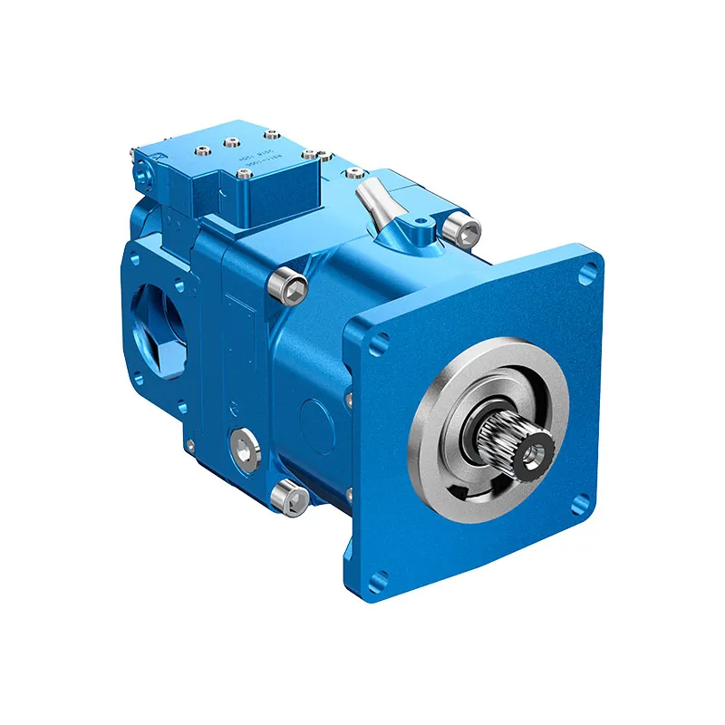
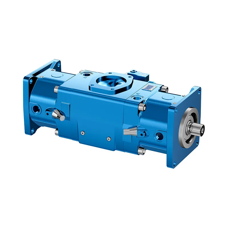
Compare related hydraulic pumps and confirm the complete configuration for your application.


Dados Técnicos
| MODELO | 66 | 90 | 130 | 180 | 250 | ||
| Design | Prato oscilante - bomba de pistões axiais | ||||||
| Tipo de montagem | Montagem com flange ou com pés. O modelo «tandem» é montado apenas com pés. | ||||||
| Ligação de tubagem Flange SAE | B | psi | 1 1/2"=3000 | 2"=3000 | 2 1/2"=3000 | 2 1/2"=3000 | 3 1/2"=500 |
| A | 1"=6000 | 1"=6000 | 1"=6000 | 1 1/4"=6000 | 1 1/4"=6000 | ||
| Sentido de rotação | No sentido dos ponteiros do relógio, olhando para a extremidade do eixo da bomba Sentido anti-horário disponível a pedido |
||||||
| Gama de velocidades | nmin | rpm | 150 | ||||
| nmáx | 1800 | ||||||
| Posição de instalação | Opcional, ver informação de montagem | ||||||
| Gama de temperaturas ambiente | min | ℉ | -4 | ||||
| máx | 122 | ||||||
| Peso | m | lb | 121 | 165 | 234 | 251 | 467 |
| Momento de inércia | J | livre pé2 | 0.38 | 0.38 | 1.068 | 1.068 | 3.465 |
HIDRÁULICO CARATERÍSTICAS
| Fluido hidráulico | Óleo hidráulico conforme a norma DIN 51524, parte 2. Consulte a secção «Dados de aplicação — Recomendações relativas aos fluidos» | |||||||
| Gama de temperaturas do fluido hidráulico | min | ℉ | -13 (no arranque) | |||||
| máx | 194 | |||||||
| Gama de viscosidade para funcionamento contínuo | min | CST | 10 | |||||
| máx | CST | 75 | ||||||
| Viscosidade máxima admissível no arranque | máx | CST | 1000 | |||||
| Filtragem | ISO 4406 | 18/15/13 | ||||||
| Geometria máxima | n=1500rpm | Vg | em3 | 4.1 | 5.5 | 7.9 | 11 | 15.2 |
| deslocamento | n=1800rpm | |||||||
| Geometria máxima | n=1500rpm | Qg | EUAboa tarde | 26 | 36 | 52 | 71 | 99 |
| caudal da bomba | n=1800rpm | 32 | 43 | 62 | 86 | 119 | ||
| Pressão da caixa | pv máx | psi | máx. 7,2 psi acima de p1. Pmáx = 58 abs. | |||||
Conduzir
| Binário máximo de condução - unidade única (p2 máx. ,η = 100%) | M1 Individual | lb.ft | 325 | 444 | 640 | 887 | 1233 |
| Consumo máximo de energia - unidade única (p2 máx., η = 1001 TP³T; n = 1800 rpm) | P1 Individual | HP | 93 | 126 | 182 | 254 | 355 |
| Binário máximo de condução limitado apenas ao veio estriado - unid. comb. | M1 Comb. | lb.ft | 2x325 | 2x444 | 2x640 | 2x887 | 2x1233 |
| MODELO | 66 | 90 | 130 | 180 | 250 | ||
| Design | Prato oscilante - bomba de pistões axiais | ||||||
| Tipo de montagem | Montagem com flange ou com pés. O modelo «tandem» é montado apenas com pés. | ||||||
| Ligação de tubagem Flange SAE | B | psi | 1 1/2"=3000 | 2"=3000 | 2 1/2"=3000 | 2 1/2"=3000 | 3 1/2"=500 |
| A | 1"=6000 | 1"=6000 | 1"=6000 | 1 1/4"=6000 | 1 1/4"=6000 | ||
| Sentido de rotação | No sentido dos ponteiros do relógio, olhando para a extremidade do eixo da bomba Sentido anti-horário disponível a pedido |
||||||
| Gama de velocidades | nmin | min-1 | 150 | ||||
| nmáx | 1800 | ||||||
| Posição de instalação | Opcional, ver informação de montagem | ||||||
| Gama de temperaturas ambiente | min | ℃ | -20 | ||||
| máx | 50 | ||||||
| Peso | m | kg | 55 | 75 | 106 | 114 | 212 |
| Momento de inércia | J | kg m2 | 0.016 | 0.016 | 0.045 | 0.045 | 0.146 |
CARATERÍSTICAS HIDRÁULICAS
| Pressão nominal (ciclo de funcionamento 100%) | PN | bar | 350 | |||||
| Pressão de entrada | P1 min | bar | 0,85abs | |||||
| P1max | bar | 50 | ||||||
| Pressão máxima segundo a norma DIN 24312 | p2max | bar | 420 | |||||
| Fluido hidráulico | Óleo hidráulico conforme a norma DIN 51524, parte 2. Consulte a secção «Dados de aplicação — Recomendações relativas aos fluidos» | |||||||
| Gama de temperaturas do fluido hidráulico | min | ℃ | -25 (no arranque) | |||||
| máx | 90 | |||||||
| Gama de viscosidade para funcionamento contínuo | min | CST | 10 | |||||
| máx | CST | 75 | ||||||
| Viscosidade máxima admissível no arranque | máx | CST | 1000 | |||||
| Filtragem | ISO 4406 | 18/15/13 | ||||||
| Geometria máxima | n=1500rpm-1 | Vg | cm3 | 66 | 90 | 130 | 180 | 250 |
| deslocamento | n=1800rpm-1 | |||||||
| Geometria máxima | n=1500rpm-1 | Qg | L/min | 99 | 135 | 195 | 270 | 375 |
| caudal da bomba | n=1800rpm-1 | 118 | 162 | 234 | 324 | 450 | ||
| Pressão da caixa | pv máx | bar | máx. 0,5 bar acima de p1. pmax = 4 bar abs. | |||||
Conduzir
| Binário máximo de condução - unidade única (p2 máx. ,η = 100%) | M1 Individual | Nm | 440 | 600 | 868 | 1202 | 1671 |
| Consumo máximo de energia - unidade única (p2 máx., η = 1001 TP³T; n = 1800 rpm-1) | P1 Individual | kW | 69 | 94 | 136 | 189 | 265 |
| Binário máximo de condução limitado apenas ao veio estriado - unid. comb. | M1 Comb. | Nm | 2x440 | 2x600 | 2x868 | 2x1202 | 2x1671 |