Wenzhou Prance Hydraulic Equipment Co., Ltd

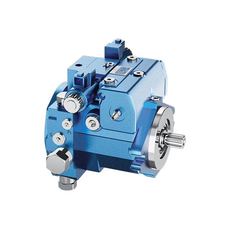
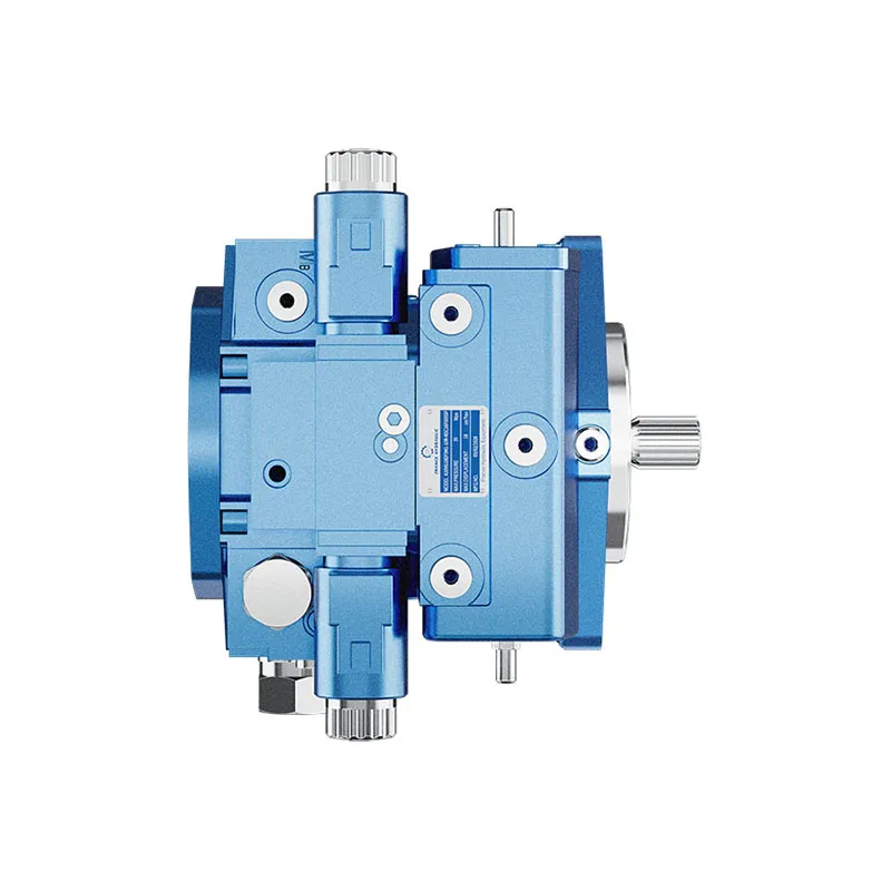
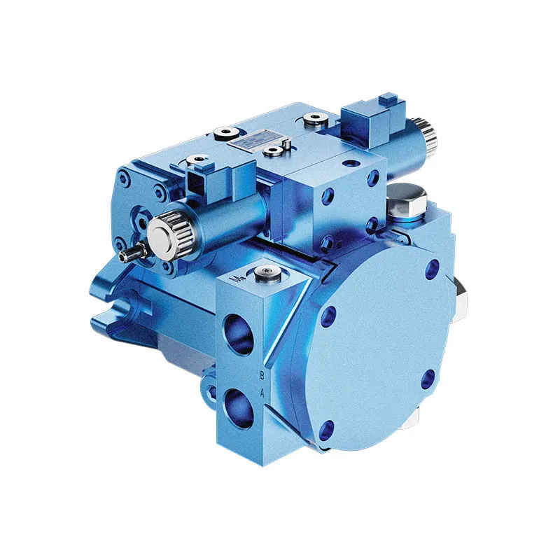
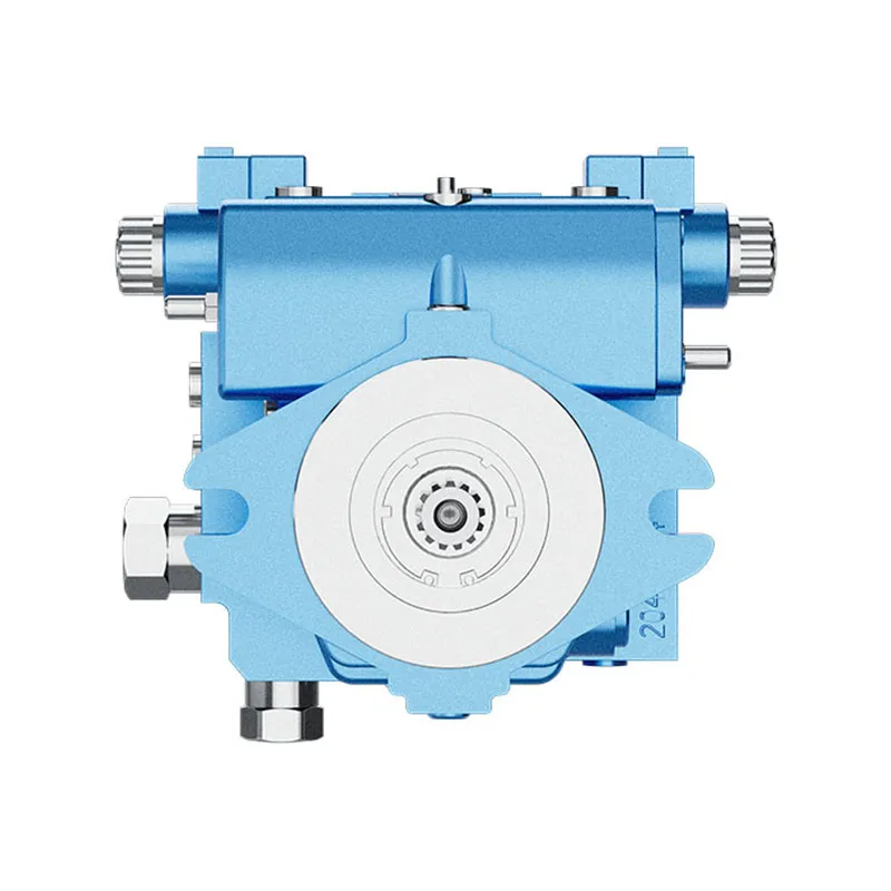


Variable Displacement Piston Pump A10VG
1.Integrated boost pump for boost and pilot oil supply
2.Flow direction changes when the swashplate is moved through the neutral position
3.High-pressure relief valves with integrated boost function
4.Boost-pressure relief valve
5.Optional with pressure cut-off
6.Large variety of controls
Descrição detalhada
This hydraulic pump is equipped with an integrated boost pump, responsible for providing stable boost pressure and pilot oil supply to ensure reliable system control and normal startup operation. When the swashplate passes through the neutral position, the pump can realize smooth switching of flow direction, avoiding impact and pressure fluctuation. It adopts high-pressure relief valves with integrated boost function, and is fitted with independent boost-pressure relief valve to realize overpressure protection and stable pressure regulation. The pump is optionally configured with pressure cut-off function to set limit pressure according to working conditions and protect components from overload damage. Meanwhile, it supports a large variety of control modes, adaptable to different working scenarios and system matching demands, featuring compact structure, stable running and convenient parameter adjustment.
Seleção e Consulta (RFQ)
Esta série de produtos deve ser selecionada em função do circuito hidráulico aprovado. Confirme o caudal ou a cilindrada necessários, a pressão contínua e de pico, a velocidade de acionamento, o tipo de controlo, o fluido e a interface de instalação antes da seleção final.
Informação a incluir no seu pedido de cotação
- Cilindrada ou caudal necessários à velocidade de funcionamento
- Pressão do sistema contínua e de pico
- Velocidade do acionamento, requisito de controlo e tipo de circuito
- Flange de fixação, veio, pórticos, requisitos de fluido e filtração
Recursos relacionados
Digitar código
| 01 | 02 | 03 | 04 | 05 | 06 | 07 | 08 | 09 | 10 | 11 | 12 | 13 | 14 | 15 | 16 | 17 | 18 | 19 | 20 | 21 | 22 | ||
| A10V | G | / | 10 | - | N | C |
Unidade de pistões axiais
| 01 | Swashplate design, variable,nominal pressure 300 bar, maximum pressure 350 bar | A10V |
Modo de funcionamento
| 02 | Bomba, circuito fechado | G |
Tamanho (NG)
| 03 | Cilindrada geométrica, ver "Dados técnicos" na página 8 | 18 | 28 | 45 | 63 |
Dispositivo de controlo
| 18 | 28 | 45 | 63 | |||||
| 04 | Proportional control
hidráulico |
pilot-pressure related, with inlet filtration in P and X1/X2 | ● | ● | ● | ● | HD3 | |
| mechanical servo | ● | ● | ● | ● | TPC | |||
| Controlo automático, relacionado com a velocidade1) | U=12V | - | ● | ● | ● | DA1 | ||
| U=24V | - | ● | ● | ● | DA2 | |||
| Hydraulic control | direct operated | ● | ● | ● | ● | DG | ||
| Controlo proporcional, elétrico | with proportional solenoid with inlet filtration in P and X1/X2 | U=12V | ● | ● | ● | ● | EP3 | |
| U=24V | ● | ● | ● | ● | EP4 | |||
| Controlo de dois pontos, elétrico | with switching solenoid | U=12V | ● | ● | ● | ● | EZ1 | |
| U=24V | ● | ● | ● | ● | EZ2 | |||
| Electric control, direct operated
two pressure reducing valves (FTDRE) |
U=12V | - | ● | ● | - | ET3 | ||
| U=24V | - | ● | ● | - | ET4 | |||
| Electric pressure controller,
negative control, with 4/2 directional valve and one pressure reducing valve1) |
de-energized, stroking chamber is controlled via X1 | U=24V | - | ● | ● | ● | ED2 | |
| de-energized, stroking chamber is controlled via X2 | U=24V | - | ● | ● | ● | ED4 | ||
Corte por pressão
| 18 | 28 | 45 | 63 | |||
| 05 | Without pressure cut-off (without code) | ● | ● | ● | ● | |
| With pressure cut-off | - | ● | ● | ● | D | |
Interruptor de posição neutra
| 18 | 28 | 45 | 63 | |||
| 06 | Sem comutador de posição neutra (sem código) | ● | ● | ● | ● | |
| Neutral position switch with DEUTSCH connector (only for HW control) | ● | ● | ● | ● | L | |
Limitador mecânico de curso2)
| 18 | 28 | 45 | 63 | |||
| 07 | Sem limitador de curso mecânico (sem código) | ● | ● | ● | ● | |
| Limitador de curso mecânico, ajustável exteriormente | ● | ● | ● | ● | L | |
porta de pressão da câmara de curso2)
| 18 | 28 | 45 | 63 | |||
| 08 | Sem bombear a porta de pressão da câmara X3, X4(without code) | ● | ● | ● | ● | |
| Stroking chamber pressure portX3, X4 | ● | ● | ● | ● | L | |
•= available ○= on request -= not available  = programa preferido
1) Only possible in combination with pressure cut-off(DA.D..., ED.D...)
2) Not available in combination with DG control device
DA control valve for NG28 ... 63
| HD | TPC | DG | Direção-Geral da Administração da Justiça | EP | Fácil | ET | ED | ||||
| 09 | Sem válvula de controlo DA | ● | ● | ● | - | ● | ● | ● | ● | 1 | |
| válvula de controlo DA, regulação fixa | ● | ● | ● | ● | ● | - | - | - | 2 | ||
| DA control valve, mechanically adjustable,
with position lever |
direction of actuation, counter-clockwise | ● | ● | ● | ● | ● | - | - | - | 3L | |
| sentido de acionamento, sentido horário | ● | ● | ● | ● | ● | - | - | - | 3R | ||
| válvula de controlo DA, regulação fixa, ligações para dispositivo de controlo piloto | ● | ● | - | ● | ● | - | - | - | 7 | ||
| DA control valve, fixed setting, and hydraulic inch valve mounted,control with mineral oil | - | - | - | ● | - | - | - | - | 8 | ||
Séries
| 10 | Series 1, index 0 | 10 |
Sentido de rotação
| 18 | 28 | 45 | 63 | ||||
| 11 | Visualizado no veio de transmissão | sentido horário | ● | ● | ● | ● | R |
| sentido anti-horário | ● | ● | ● | ● | L | ||
Material de selagem
| 18 | 28 | 45 | 63 | |||
| 12 | NBR (nitrile rubber), shaft seal made of FKM (fluoroelastomer) | ● | ● | ● | ● | N |
Veio de transmissão
| 18 | 28 | 45 | 63 | ||||
| 13 | Veio estriado
ANSI B92.1a-1976 |
para bomba individual | ● | ● | ● | ● | S |
| for combination pump | ● | ● | ● | ● | T | ||
Flange de montagem
| 18 | 28 | 45 | 63 | ||||
| 14 | SAE J744 | com 2 furos | ● | ● | ● | ● | C |
Porto de trabalho
| 15 | Port thread: Metric with profile sealing ring sealing according to DIN 3852
Fastening thread at the SAE working port and through drive: Metric according to DIN 13 |
18 | 28 | 45 | 63 | ||
| SAE working port A and B, same side left | suction port S bottom | - | ● | ● | ● | 10 | |
| SAE working port A and B, same side right | suction port S at top
(externally piped up, except for DG) |
- | ● | ● | ● | 13 | |
| Port and working port thread: Metric with profile sealing ring sealing according to DIN 3852
Fastening thread at the through drive: Metric according to DIN 13 |
18 | 28 | 45 | 63 | |||
| Threaded port A and B, same side right | suction port S bottom | ● | - | - | - | 16 | |
Bomba de reforço
| 18 | 28 | 45 | 63 | ||||
| 16 | Sem bomba de reforço integrada | sem acionamento direto | ● | ● | ● | ● | N |
| com passagem direta | ● | ● | ● | ● | K | ||
| Bomba de reforço integrada | com e sem eixo passante | ● | ● | ● | ● | F | |
•= available ○= on request -= not available = programa preferido
Através da unidade de atendimento automóvel3)
| 18 | 28 | 45 | 63 | |||||
| 17 | Without through drive, only for version N and F (position 16) | ● | ● | ● | ● | 00 | ||
| Flange SAE J744 | Cubo para veio estriado4) | |||||||
| 82-2 (A) | 5/8 pol. | 9T 16/32DP | ● | ● | ● | ● | 01 | |
| 3/4 pol | 11T 16/32DP | - | ● | ● | ● | 52 | ||
| 101-2(B) | 7/8 in | 13T 16/32DP | ● | ● | ● | ● | 02 | |
| 1 pol | 15T 16/32DP | - | ● | ● | ● | 04 | ||
| 127-2 (C) | 1 1/4 in | 14T 12/24DP | - | - | - | ● | 07 | |
Válvula de alívio de alta pressão
| Setting range ΔpHD | 18 | 28 | 45 | 63 | ||||
| 18 | Válvula de alívio de alta pressão
direct operated, fixed setting |
250 ... 320 bar | sem desvio | ● | ● | ● | ● | 3 |
| com bypass | ● | ● | ● | ● | 5 | |||
| 100 ... 250 bar | sem desvio | - | ● | ● | ● | 4 | ||
| com bypass | - | ● | ● | ● | 6 | |||
Circuito de reforço de filtração/alimentação de pressão de reforço externa
| 18 | 28 | 45 | 63 | |||
| 19 | Filtração na linha de aspiração da bomba de reforço | ● | ● | ● | ● | S |
| Filtração na linha de pressão da bomba de reforço
Ports for external boost circuit filtration (Fe and G (Fa)) |
- | ●5) | ●5) | ● | D | |
| External boost pressure supply (on version without integrated boost pump - N, K) | ● | ● | ● | ● | E | |
Connector for solenoids6)
| 18 | 28 | 45 | 63 | ||||
| 20 | Without connector (without code), only with purely hydraulic controls | ● | ● | ● | ● | ||
| DEUTSCH molded connector
2-pin, DT04-2P |
without suppressor diode | ● | ● | ● | ● | P | |
| with suppressor diode (only for EZ, DA and ED switching solenoid) | ● | ● | ● | ● | Q | ||
Flushing valve
| 18 | 28 | 45 | 63 | ||||
| 21 | Without flushing valve (without code) | ● | ● | ● | ● | ||
| Flushing valve | SAE connection diagram, metric mounting | ● | ● | ● | ● | 1 | |
| metric threaded ports | ● | ● | ● | ● | 3 | ||
Standard/special version
| 22 | Standard version | sem código | |
| Special version | -S |
•= disponível ○= a pedido -= não disponível = programa preferido
Notice
▶Note the project planning notes on page 59!
▶In addition to the type code, please specify the relevant technical data when placing your order.
▶Please note that not all type code combinations are available although the individual functions are marked as being available.
3)Specifications for version with integrated boost pump,please contact us for version without boost pump
4)Hub for splined shaft according to ANSI B92.1a-1976(drive shaft allocation according to SAE J744)
5) Pressure filtration is not possible in connection with DA control valve
6) Connectors for other electric components may deviate
Dados técnicos
| Tamanho | NG | 18 | 28 | 45 | 63 | |||
| Geometric displacement, per revolution | ||||||||
| variable pump | Vg max
|
cm3 | 18 | 28 | 46 | 63 | ||
| boost pump (at p = 20 bar) | Vg Sp
|
cm3 | 5.5 | 6.1 | 8.6 | 14.9 | ||
| Velocidade de rotação1) | maximum at VG Max | nnome | min-1 | 4000 | 3900 | 3300 | 3000 | |
| limited maximum2) | nmax1 | min-1 | 4850 | 4200 | 3550 | 3250 | ||
| intermittent maximum3) | nmax2 | min-1 | 5200 | 4500 | 3800 | 3500 | ||
| minimum | nmin | min-1 | 500 | 500 | 500 | 500 | ||
| Fluxo | at nnome e VG Max | qv | L/min | 72 | 109 | 152 | 189 | |
| Energia4) | at nnome, VG Max and | Δp =300 bar | P | kW | 36 | 54.6 | 75.9 | 94.5 |
| Torque4) | with VG Max and | Δp =300 bar | M | Nm | 86 | 134 | 215 | 301 |
| Δp =100 bar | M | Nm | 28.6 | 44.6 | 72 | 100.3 | ||
| Rotary stiffness of drive shaft | S | c | kNm/rad | 20.28 | 32.14 | 53.40 | 78.37 | |
| T | c | kNm/rad | - | - | 73.80 | 92.37 | ||
| Moment of inertia of the rotary group | JTW | kgm2 | 0.00093 | 0.0017 | 0.0033 | 0.0056 | ||
| Maximum angular acceleration5) | α | rad/s2 | 6800 | 5500 | 4000 | 3300 | ||
| Case volume | V | l | 0.45 | 0.64 | 0.75 | 1.1 | ||
| Weight (without through drive) approx.6) | m | kg | 18 | 25 | 27 | 39 | ||
Notice
▶Theoretical values, without efficiency and tolerances;values rounded
▶Operation above the maximum values or below the minimum values may result in a loss of function,a reduced service life or in the destruction of the axial piston unit. Prance recommends testing the loads by means of experiment or calculation /simulation and comparison with the permissible values.
Determining the operating characteristics
| Fluxo | qv=(Vg ∙ n ∙ ηv) / 1000 | L/min |
| Torque | M=(Vg ∙ Δp) /(20 ∙ π ∙ ηhm) | Nm |
| Energia | P=(2π ∙ M ∙ n)/60000=(qv ∙ Δp)/(600 ∙ ηt) | kW |
Key
Vg Displacement per revolution in [cm3]
Δp Differential pressure [bar]
n Rotational speed [rpm]
ηv Volumetric efficiency
ηhm Hydraulic-mechanical efficiency
ηt Total efficiency (ηt= ηv*ηhm)
1)The values are applicable:
- for the optimum viscosity range from Vopt = 36 ... 16 mm2/s
- for hydraulic fluid based on mineral oils (for HF hydraulic fluids,observe the technical data in 90225)
2)Valid at half corner power (e.g. at Vg max and pi/2)
3) Valid at Ap = 70 ... 150 bar or Ap < 300 bar and t < 0.1 s
4)Without boost pump
5)The data are valid for values between the minimum required and maximum permissible rotational speed.
Valid for external excitation (e. g. diesel engine 2 to 8 times rotary frequency; cardan shaft twice the rotary frequency).
The limit value is only valid for a single pump.
The load capacity of the connection parts must be considered.
6)Weight may vary by equipment.
Permissible radial and axial loading of the drive shaft
| Tamanho | NG | 18 | 28 | 28 | 45 | 45 | 63 | 63 | ||
| Veio de transmissão | in | 7/8 | 1 | 1 1/4 | 1 | 1 1/4 | 1 1/4 | 1 3/8 | ||
| Maximum radial
force at distance a (to the shaft collar) |
 |
Fq máx | N | 1300 | 2500 | 2500 | 3600 | 3600 | 5000 | 5000 |
| a | mm | 16.5 | 17.5 | 17.5 | 17.5 | 17.5 | 17.5 | 17.5 | ||
| Maximum axial force | 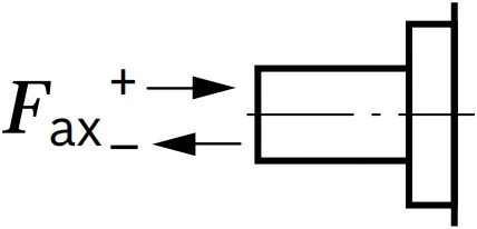 |
+Fax max | N | 973 | 987 | 987 | 1500 | 1500 | 2200 | 2200 |
| -Fax max | N | 973 | 987 | 987 | 1500 | 1500 | 2200 | 2200 | ||
Notice
▶The axial and radial loading generally influence the bearing service life.
▶Special requirements apply in the case of belt drive and cardan shaft. Please contact us.
Permissible input and through-drive torques
| Tamanho | NG | 18 | 28 | 45 | 63 | ||
| Torque at VG Max and Δp = 300 bar1) | M | Nm | 86 | 134 | 220 | 301 | |
| Maximum input torque on drive shaft2) | |||||||
| ANSI B92.1a (SAE J744) | S | ME máx | Nm | 192 | 314 | 314 | 602 |
| in | 7/8 | 1 | 1 | 1 1/4 | |||
| T | ME máx | Nm | - | 602 | 602 | 970 | |
| in | - | 1 1/4 | 1 1/4 | 1 3/8 | |||
| Maximum through-drive torque | ME máx | Nm | 112 | 220 | 314 | 439 | |
Distribution of torques
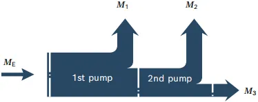
| Torque at 1st pump | M1 |
| Torque at 2nd pump | M2 |
| Torque at 3rd pump | M3 |
| Input torque | ME=M1+M2+M3 |
| ME < ME max | |
| Through∙drive torque | MD=M2+M3 |
| MD < MD max |
1) Efficiency not considered
2) For drive shafts free of radial force
