شركة ونزهو برانس للمعدات الهيدروليكية المحدودة

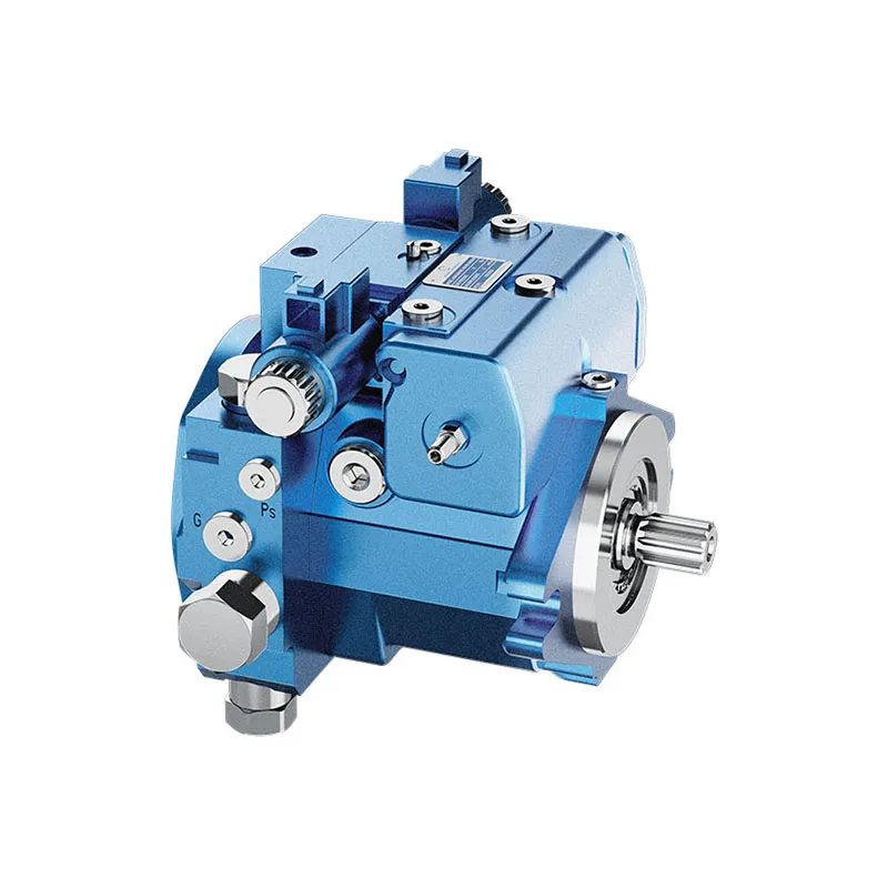
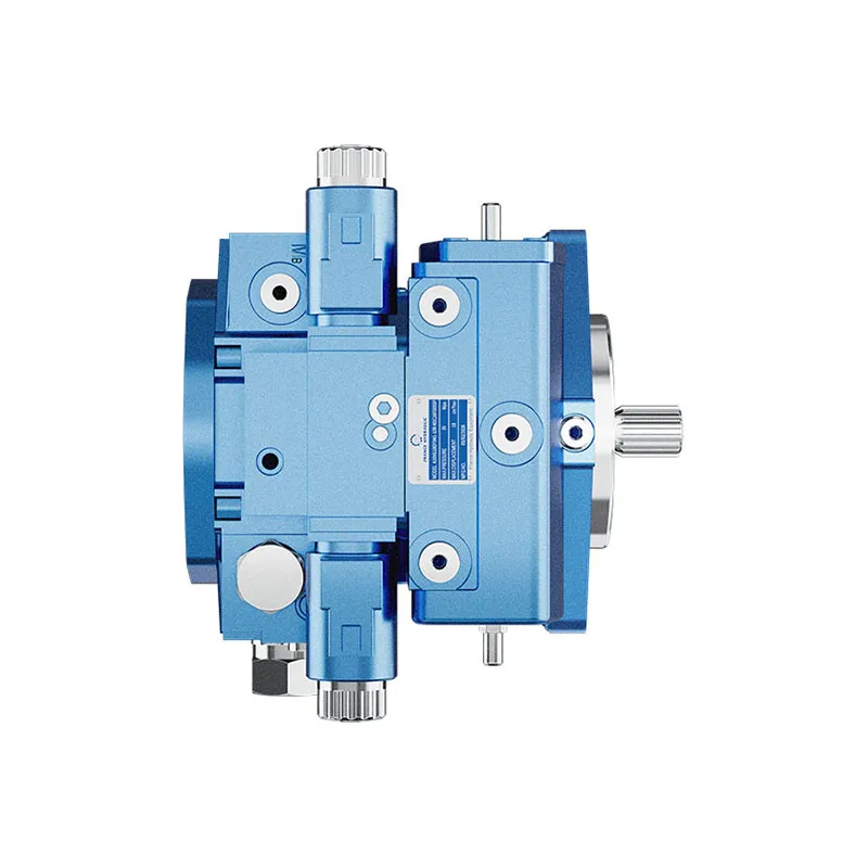
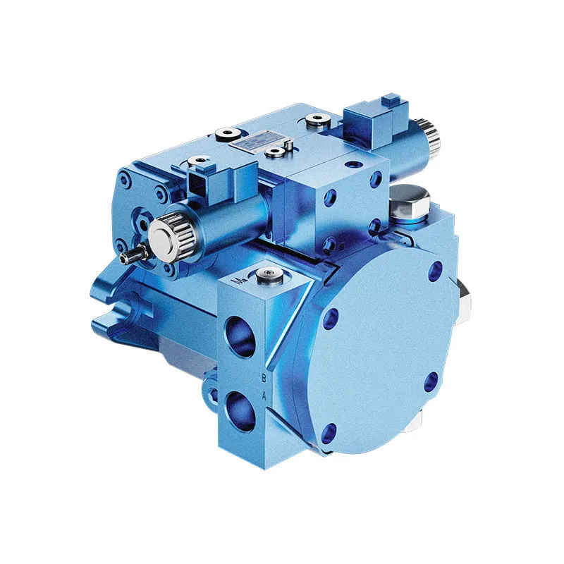
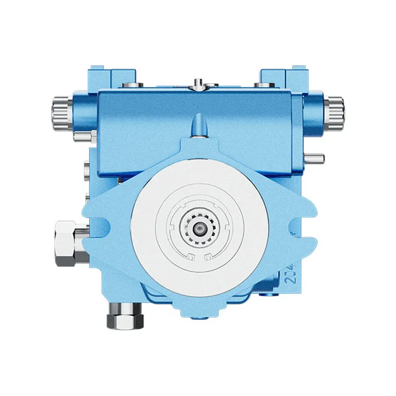


Variable Displacement Piston Pump A10VG
1.Integrated boost pump for boost and pilot oil supply
2.Flow direction changes when the swashplate is moved through the neutral position
3.High-pressure relief valves with integrated boost function
4.Boost-pressure relief valve
5.Optional with pressure cut-off
6.Large variety of controls
وصف تفصيلي
This hydraulic pump is equipped with an integrated boost pump, responsible for providing stable boost pressure and pilot oil supply to ensure reliable system control and normal startup operation. When the swashplate passes through the neutral position, the pump can realize smooth switching of flow direction, avoiding impact and pressure fluctuation. It adopts high-pressure relief valves with integrated boost function, and is fitted with independent boost-pressure relief valve to realize overpressure protection and stable pressure regulation. The pump is optionally configured with pressure cut-off function to set limit pressure according to working conditions and protect components from overload damage. Meanwhile, it supports a large variety of control modes, adaptable to different working scenarios and system matching demands, featuring compact structure, stable running and convenient parameter adjustment.
التقييم وطلب عرض الأسعار
يجب اختيار سلسلة المنتجات هذه بما يتوافق مع الدائرة الهيدروليكية المعتمدة. تأكد من تحديد التدفق أو الإزاحة المطلوبة، والضغط المستمر وأقصى ضغط، وسرعة الدوران، ونظام التحكم، ونوع السائل، وواجهة التركيب قبل إجراء الاختيار النهائي.
المعلومات التي يجب تضمينها في طلب عرض الأسعار الخاص بك
- الازاحة أو التدفق المطلوب عند سرعة التشغيل
- ضغط النظام المستمر والقصوي
- سرعة المحرك، متطلبات التحكم ونوع الدائرة
- شفة التركيب، العمود، المنافذ، السوائل ومتطلبات الترشيح
الموارد ذات الصلة
اطلب عرض سعر · مركز التنزيل · تصنيع أصلي / تصنيع تصميمي أصلي
اكتب رمزاً
| 01 | 02 | 03 | 04 | 05 | 06 | 07 | 08 | 09 | 10 | 11 | 12 | 13 | 14 | 15 | 16 | 17 | 18 | 19 | 20 | 21 | 22 | ||
| A10V | G | / | 10 | - | N | C |
وحدة كباس محوري
| 01 | Swashplate design, variable,nominal pressure 300 bar, maximum pressure 350 bar | A10V |
نمط التشغيل
| 02 | مضخة، دائرة مغلقة | G |
المقاس (NG)
| 03 | الإزاحة الهندسية، انظر "البيانات الفنية" في الصفحة 8 | 18 | 28 | 45 | 63 |
جهاز تحكم
| 18 | 28 | 45 | 63 | |||||
| 04 | Proportional control
hydraulic |
pilot-pressure related, with inlet filtration in P and X1/X2 | ● | ● | ● | ● | HD3 | |
| mechanical servo | ● | ● | ● | ● | واجب منزلي | |||
| تحكم آلي، متعلق بالسرعة1) | الجهد = 12 فولت | - | ● | ● | ● | DA1 | ||
| الجهد = 24 فولت | - | ● | ● | ● | DA2 | |||
| Hydraulic control | direct operated | ● | ● | ● | ● | دي جي | ||
| تحكم نسبي، كهربائي | with proportional solenoid with inlet filtration in P and X1/X2 | الجهد = 12 فولت | ● | ● | ● | ● | الحلقة 3 | |
| الجهد = 24 فولت | ● | ● | ● | ● | الحلقة الرابعة | |||
| تحكم بنقطتين، كهربائي | with switching solenoid | الجهد = 12 فولت | ● | ● | ● | ● | إي زي 1 | |
| الجهد = 24 فولت | ● | ● | ● | ● | EZ2 | |||
| Electric control, direct operated
two pressure reducing valves (FTDRE) |
الجهد = 12 فولت | - | ● | ● | - | ET3 | ||
| الجهد = 24 فولت | - | ● | ● | - | ET4 | |||
| Electric pressure controller,
negative control, with 4/2 directional valve and one pressure reducing valve1) |
de-energized, stroking chamber is controlled via X1 | الجهد = 24 فولت | - | ● | ● | ● | ED2 | |
| de-energized, stroking chamber is controlled via X2 | الجهد = 24 فولت | - | ● | ● | ● | ED4 | ||
قطع الضغط
| 18 | 28 | 45 | 63 | |||
| 05 | Without pressure cut-off (without code) | ● | ● | ● | ● | |
| With pressure cut-off | - | ● | ● | ● | D | |
مفتاح الوضع المحايد
| 18 | 28 | 45 | 63 | |||
| 06 | بدون مفتاح وضع حيادي (بدون رمز) | ● | ● | ● | ● | |
| Neutral position switch with DEUTSCH connector (only for HW control) | ● | ● | ● | ● | L | |
محدد الشوط الميكانيكي2)
| 18 | 28 | 45 | 63 | |||
| 07 | بدون محدث شوط ميكانيكي (بدون رمز) | ● | ● | ● | ● | |
| محدد شوط ميكانيكي، قابل للتعديل من الخارج | ● | ● | ● | ● | L | |
منفذ ضغط غرفة الشوط2)
| 18 | 28 | 45 | 63 | |||
| 08 | بدون ضغط منفذ ضغط حجرة (إكس)3, ، X4(without code) | ● | ● | ● | ● | |
| Stroking chamber pressure portX3, ، X4 | ● | ● | ● | ● | L | |
•= available ○= on request -= not available  البرنامج المفضل
1) Only possible in combination with pressure cut-off(DA.D..., ED.D...)
2) Not available in combination with DG control device
DA control valve for NG28 ... 63
| عالي الدقة | واجب منزلي | دي جي | دا | إي بي | سهل | ET | ED | ||||
| 09 | بدون صمام تحكم DA | ● | ● | ● | - | ● | ● | ● | ● | 1 | |
| صمام تحكم مزدوج الفعل، إعداد ثابت | ● | ● | ● | ● | ● | - | - | - | 2 | ||
| DA control valve, mechanically adjustable,
with position lever |
direction of actuation, counter-clockwise | ● | ● | ● | ● | ● | - | - | - | 3L | |
| اتجاه التشغيل، في اتجاه عقارب الساعة | ● | ● | ● | ● | ● | - | - | - | ٣ آر | ||
| صمام تحكم مزدوج الفعل، إعداد ثابت، فتحات لجهاز التحكم التجريبي | ● | ● | - | ● | ● | - | - | - | 7 | ||
| DA control valve, fixed setting, and hydraulic inch valve mounted,control with mineral oil | - | - | - | ● | - | - | - | - | 8 | ||
مسلسل
| 10 | Series 1, index 0 | 10 |
اتجاه الدوران
| 18 | 28 | 45 | 63 | ||||
| 11 | تمت معاينته على عمود الدوران | مع عقارب الساعة | ● | ● | ● | ● | R |
| عكس عقارب الساعة | ● | ● | ● | ● | L | ||
مادة مانعة للتسرب
| 18 | 28 | 45 | 63 | |||
| 12 | NBR (nitrile rubber), shaft seal made of FKM (fluoroelastomer) | ● | ● | ● | ● | N |
عمود الدوران
| 18 | 28 | 45 | 63 | ||||
| 13 | عمود مسنن
ANSI B92.1a-1976 |
لمضخة واحدة | ● | ● | ● | ● | S |
| for combination pump | ● | ● | ● | ● | T | ||
شفة التركيب
| 18 | 28 | 45 | 63 | ||||
| 14 | SAE J744 | ثقبان | ● | ● | ● | ● | C |
منفذ عامل
| 15 | Port thread: Metric with profile sealing ring sealing according to DIN 3852
Fastening thread at the SAE working port and through drive: Metric according to DIN 13 |
18 | 28 | 45 | 63 | ||
| SAE working port A and B, same side left | suction port S bottom | - | ● | ● | ● | 10 | |
| SAE working port A and B, same side right | suction port S at top
(externally piped up, except for DG) |
- | ● | ● | ● | 13 | |
| Port and working port thread: Metric with profile sealing ring sealing according to DIN 3852
Fastening thread at the through drive: Metric according to DIN 13 |
18 | 28 | 45 | 63 | |||
| Threaded port A and B, same side right | suction port S bottom | ● | - | - | - | 16 | |
Boost pump
| 18 | 28 | 45 | 63 | ||||
| 16 | Without integrated boost pump | بدون محرك مرور | ● | ● | ● | ● | N |
| with through drive | ● | ● | ● | ● | K | ||
| Integrated boost pump | with and without through drive | ● | ● | ● | ● | F | |
•= available ○= on request -= not available البرنامج المفضل
من خلال القيادة3)
| 18 | 28 | 45 | 63 | |||||
| 17 | Without through drive, only for version N and F (position 16) | ● | ● | ● | ● | 00 | ||
| Flange SAE J744 | سرّة لعمود مسنن4) | |||||||
| ٢-٨٢ (أ) | ٥/٨ بوصة | 9T 16/32DP | ● | ● | ● | ● | 01 | |
| ٣/٤ بوصة | 11 سن 16/32DP | - | ● | ● | ● | 52 | ||
| 101-2(ب) | 7/8 in | 13 سن 16/32DP | ● | ● | ● | ● | 02 | |
| ١ بوصة | 15T 16/32DP | - | ● | ● | ● | 04 | ||
| 127-2 (C) | 1 1/4 in | 14 سن 12/24 دي بي | - | - | - | ● | 07 | |
High-pressure relief valve
| Setting range Δpعالي الدقة | 18 | 28 | 45 | 63 | ||||
| 18 | High-pressure relief valve
direct operated, fixed setting |
250 ... 320 bar | without bypass | ● | ● | ● | ● | 3 |
| with bypass | ● | ● | ● | ● | 5 | |||
| 100 ... 250 bar | without bypass | - | ● | ● | ● | 4 | ||
| with bypass | - | ● | ● | ● | 6 | |||
Filtration boost circuit/external boost pressure supply
| 18 | 28 | 45 | 63 | |||
| 19 | Filtration in the boost pump suction line | ● | ● | ● | ● | S |
| Filtration in the boost pump pressure line
Ports for external boost circuit filtration (Fe and G (Fa)) |
- | ●5) | ●5) | ● | D | |
| External boost pressure supply (on version without integrated boost pump - N, K) | ● | ● | ● | ● | E | |
Connector for solenoids6)
| 18 | 28 | 45 | 63 | ||||
| 20 | Without connector (without code), only with purely hydraulic controls | ● | ● | ● | ● | ||
| DEUTSCH molded connector
2-pin, DT04-2P |
without suppressor diode | ● | ● | ● | ● | P | |
| with suppressor diode (only for EZ, DA and ED switching solenoid) | ● | ● | ● | ● | Q | ||
Flushing valve
| 18 | 28 | 45 | 63 | ||||
| 21 | Without flushing valve (without code) | ● | ● | ● | ● | ||
| Flushing valve | SAE connection diagram, metric mounting | ● | ● | ● | ● | 1 | |
| metric threaded ports | ● | ● | ● | ● | 3 | ||
Standard/special version
| 22 | Standard version | بدون رمز | |
| Special version | -S |
•= متوفر ○= عند الطلب -= غير متوفر البرنامج المفضل
Notice
▶Note the project planning notes on page 59!
▶In addition to the type code, please specify the relevant technical data when placing your order.
▶Please note that not all type code combinations are available although the individual functions are marked as being available.
3)Specifications for version with integrated boost pump,please contact us for version without boost pump
4)Hub for splined shaft according to ANSI B92.1a-1976(drive shaft allocation according to SAE J744)
5) Pressure filtration is not possible in connection with DA control valve
6) Connectors for other electric components may deviate
البيانات الفنية
| حجم | غير مقبول | 18 | 28 | 45 | 63 | |||
| Geometric displacement, per revolution | ||||||||
| variable pump | Vg max
|
سم3 | 18 | 28 | 46 | 63 | ||
| boost pump (at p = 20 bar) | Vg Sp
|
سم3 | 5.5 | 6.1 | 8.6 | 14.9 | ||
| Rotational speed1) | maximum at Vجي ماكس | nnom | min-1 | 4000 | 3900 | 3300 | 3000 | |
| limited maximum2) | nmax1 | min-1 | 4850 | 4200 | 3550 | 3250 | ||
| intermittent maximum3) | nmax2 | min-1 | 5200 | 4500 | 3800 | 3500 | ||
| minimum | nmin | min-1 | 500 | 500 | 500 | 500 | ||
| تدفق | at nnom and Vجي ماكس | qv | لتر/دقيقة | 72 | 109 | 152 | 189 | |
| Power4) | at nnom, Vجي ماكس and | Δp =300 bar | P | كيلوواط | 36 | 54.6 | 75.9 | 94.5 |
| Torque4) | with Vجي ماكس and | Δp =300 bar | M | لا شيء جديد | 86 | 134 | 215 | 301 |
| Δp =100 bar | M | لا شيء جديد | 28.6 | 44.6 | 72 | 100.3 | ||
| Rotary stiffness of drive shaft | S | c | kNm/rad | 20.28 | 32.14 | 53.40 | 78.37 | |
| T | c | kNm/rad | - | - | 73.80 | 92.37 | ||
| Moment of inertia of the rotary group | JTW | kgm2 | 0.00093 | 0.0017 | 0.0033 | 0.0056 | ||
| Maximum angular acceleration5) | α | rad/s2 | 6800 | 5500 | 4000 | 3300 | ||
| Case volume | V | l | 0.45 | 0.64 | 0.75 | 1.1 | ||
| Weight (without through drive) approx.6) | m | kg | 18 | 25 | 27 | 39 | ||
Notice
▶Theoretical values, without efficiency and tolerances;values rounded
▶Operation above the maximum values or below the minimum values may result in a loss of function,a reduced service life or in the destruction of the axial piston unit. Prance recommends testing the loads by means of experiment or calculation /simulation and comparison with the permissible values.
Determining the operating characteristics
| تدفق | qv=(Vg ∙ n ∙ ηv) / 1000 | لتر/دقيقة |
| Torque | M=(Vg ∙ Δp) /(20 ∙ π ∙ ηhm) | لا شيء جديد |
| Power | P=(2π ∙ M ∙ n)/60000=(qv ∙ Δp)/(600 ∙ ηt) | كيلوواط |
Key
Vg Displacement per revolution in [cm3]
Δp Differential pressure [bar]
n Rotational speed [rpm]
ηv Volumetric efficiency
ηhm Hydraulic-mechanical efficiency
ηt Total efficiency (ηt= ηv*ηhm)
1)The values are applicable:
- for the optimum viscosity range from Vopt = 36 ... 16 mm2/s
- for hydraulic fluid based on mineral oils (for HF hydraulic fluids,observe the technical data in 90225)
2)Valid at half corner power (e.g. at Vg max and pi/2)
3) Valid at Ap = 70 ... 150 bar or Ap < 300 bar and t < 0.1 s
4)Without boost pump
5)The data are valid for values between the minimum required and maximum permissible rotational speed.
Valid for external excitation (e. g. diesel engine 2 to 8 times rotary frequency; cardan shaft twice the rotary frequency).
The limit value is only valid for a single pump.
The load capacity of the connection parts must be considered.
6)Weight may vary by equipment.
Permissible radial and axial loading of the drive shaft
| حجم | غير مقبول | 18 | 28 | 28 | 45 | 45 | 63 | 63 | ||
| عمود الدوران | in | 7/8 | 1 | 1 1/4 | 1 | 1 1/4 | 1 1/4 | 1 3/8 | ||
| Maximum radial
force at distance a (to the shaft collar) |
 |
Fq الحد الأقصى | N | 1300 | 2500 | 2500 | 3600 | 3600 | 5000 | 5000 |
| a | mm | 16.5 | 17.5 | 17.5 | 17.5 | 17.5 | 17.5 | 17.5 | ||
| Maximum axial force | 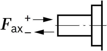 |
+Fax max | N | 973 | 987 | 987 | 1500 | 1500 | 2200 | 2200 |
| -Fax max | N | 973 | 987 | 987 | 1500 | 1500 | 2200 | 2200 | ||
Notice
▶The axial and radial loading generally influence the bearing service life.
▶Special requirements apply in the case of belt drive and cardan shaft. Please contact us.
Permissible input and through-drive torques
| حجم | غير مقبول | 18 | 28 | 45 | 63 | ||
| Torque at Vجي ماكس and Δp = 300 bar1) | M | لا شيء جديد | 86 | 134 | 220 | 301 | |
| Maximum input torque on drive shaft2) | |||||||
| ANSI B92.1a (SAE J744) | S | ME الحد الأقصى | لا شيء جديد | 192 | 314 | 314 | 602 |
| in | 7/8 | 1 | 1 | 1 1/4 | |||
| T | ME الحد الأقصى | لا شيء جديد | - | 602 | 602 | 970 | |
| in | - | 1 1/4 | 1 1/4 | 1 3/8 | |||
| Maximum through-drive torque | ME الحد الأقصى | لا شيء جديد | 112 | 220 | 314 | 439 | |
Distribution of torques
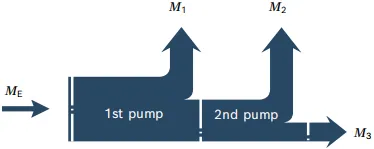
| Torque at 1st pump | M1 |
| Torque at 2nd pump | M2 |
| Torque at 3rd pump | M3 |
| Input torque | ME=M1+M2+M3 |
| ME < ME max | |
| Through∙drive torque | MD=M2+M3 |
| MD < MD max |
1) Efficiency not considered
2) For drive shafts free of radial force
