شركة ونزهو برانس للمعدات الهيدروليكية المحدودة


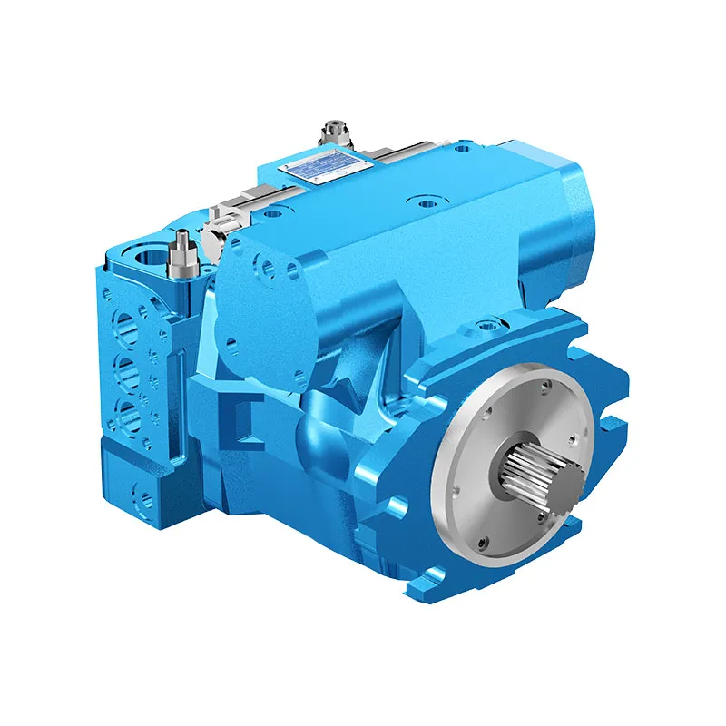
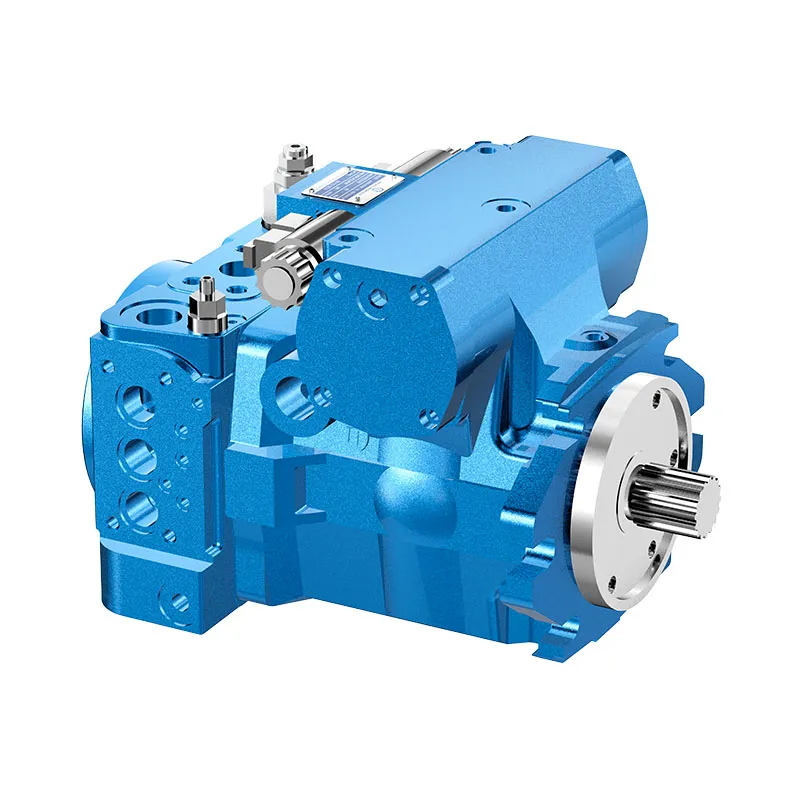
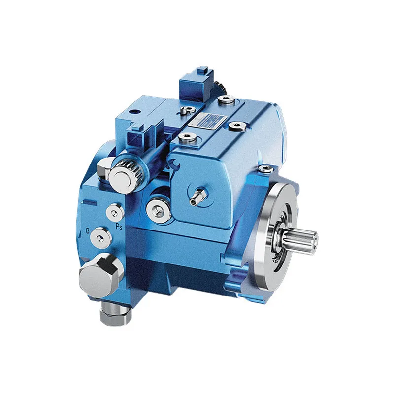
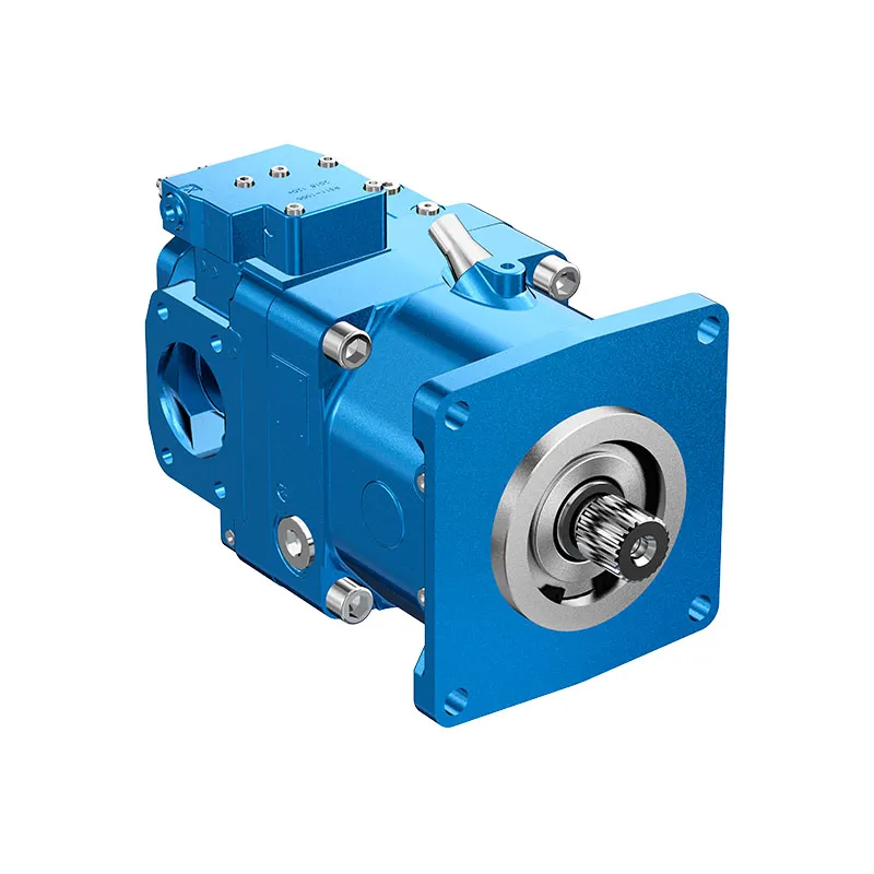
A4VG Closed Circuit Variable Piston Pump
The A4VG variable displacement pump is offered for closed-circuit hydraulic drives. The boost supply, high-pressure loop and control arrangement form one selection problem, especially where a drive reverses or sees an overrunning load.
- Integrated boost and pilot supply
- Reversible flow through neutral
- High-pressure relief functions
- Pressure cut-off configuration
PRANCE HYDRAULIC · PRODUCT SERIES
A4VG Closed Circuit Variable Piston Pump
Axial piston; variable swashplate · Closed circuit
The A4VG variable displacement pump is offered for closed-circuit hydraulic drives. The boost supply, high-pressure loop and control arrangement form one selection problem, especially where a drive reverses or sees an overrunning load.
Model
✓
Request a Quotationعرض البيانات الفنية وورقة البياناتA4VGAxial piston; variable swashplate
Confirm the complete model and approved specification with Prance Hydraulic. Product-series references alone do not establish interchangeability.
Configuration review · Technical documentation · Product selection
تفاصيل المنتج
- Integrated boost and pilot supply
- Reversible flow through neutral
- High-pressure relief functions
- Pressure cut-off configuration
CATEGORIES: مضخة مكبسية, مضخة ذات إزاحة متغيرة
A4VG Features & Application
Integrated boost and pilot supply
Account for pilot or replenishment demand and the relevant pressure limits. Include filtration and the return or drain route in the circuit review.
Reversible flow through neutral
Review combined drive torque and simultaneous demand, including any additional pump connected to the drive.
High-pressure relief functions
Keep continuous, intermittent and peak conditions separate. Use the row for the selected size and configuration.
Pressure cut-off configuration
Keep continuous, intermittent and peak conditions separate. Use the row for the selected size and configuration.
A4VG Specifications
| Series / model | A4VG |
|---|---|
| Product type | A4VG Closed Circuit Variable Piston Pump |
| تصميم | Axial piston; variable swashplate |
| Circuit / selection | Closed circuit |
| Published nominal sizes | 28, 40, 56, 71, 90, 125 and 180 |
| Circuit | Closed circuit |
A4VG Selection & Configuration
The A4VG variable displacement pump is offered for closed-circuit hydraulic drives. The boost supply, high-pressure loop and control arrangement form one selection problem, especially where a drive reverses or sees an overrunning load.
Check pressure cut-off, high-pressure relief and boost-pressure settings separately. Provide the motor, flushing demand, maximum drive speed and control signal. Confirm the model series and through-drive requirements before comparing another A4VG or AA4VG unit.

Your Application.
The Right Configuration.
Hydraulic pumps · Hydraulic motors · Hydraulic valves
Send the MS nameplate, operating requirements and installation drawing for a configuration review before quoting.
- Model review — send the full model code or an existing nameplate photograph.
- Interface matching — confirm shaft, mounting flange, rotation and ports.
- Operating conditions — provide flow, pressure, speed, fluid and duty cycle.
- Documentation — request the relevant product data and drawings for your review.

A4VG Buying Guide
Use this sequence to prepare the A4VG configuration for review and quotation.
- Define required flow at the actual drive speed and continuous pressure.
- Identify peak pressure, duration and the work cycle.
- Confirm the selected displacement control and any auxiliary-drive requirement.
- Match rotation viewed from the shaft end, shaft, flange and ports.
- Review inlet conditions, drain routing and the installation envelope.
- Confirm fluid, viscosity, temperature, filtration and seals.
- Approve the complete model, control, drawing, quantity and delivery terms.

Selection, Documentation & Project Support

Selection Support
Learn more →Share your hydraulic circuit, operating point and installation requirements for a configuration discussion.
Flow · Pressure · Speed · Interfaces

Technical Resources
Learn more →Review product documentation, model codes and technical data before finalizing the specification.
Datasheets · Model codes · Drawings

Project Inquiries
Learn more →Send your required model, quantity, application and project requirements to discuss your inquiry.
Product inquiries · Configuration review
Configuration, Quantity & Delivery
Confirm the complete MS code, approved drawing and operating limits. Availability, quantity, documentation and delivery date are confirmed in the quotation.
Discuss Your A4VG Application
Send the full model code, operating duty, installation details and quantity.
Request a A4VG QuotationA4VG Questions Before Ordering
What type of product is the A4VG?
A4VG Closed Circuit Variable Piston Pump. Design: Axial piston; variable swashplate. Closed circuit. Confirm the complete order code for the offered version.
Can a similar pump replace the A4VG?
cURL Too many subrequests by single Worker invocation. To configure this limit, refer to https://developers.cloudflare.com/workers/wrangler/configuration/#limits.
cURL Too many subrequests by single Worker invocation. To configure this limit, refer to https://developers.cloudflare.com/workers/wrangler/configuration/#limits
Define required flow at the actual drive speed and continuous pressure. Identify peak pressure, duration and the work cycle. Attach the nameplate, complete order code, installation drawing and required quantity.
A4VG Technical Data & Documents
View A4VG catalog data and operating conditions
cURL Too many subrequests by single Worker invocation. To configure this limit, refer to https://developers.cloudflare.com/workers/wrangler/configuration/#limits.
البيانات الفنية
| Size Displacement.geometric.per revolution | غير مقبول | 28 | 40 | 56 | 71 | 90 | 125 | 180 | |||
| مضخة متغيرة الإزاحة | Vجي ماكس | سم3 | 28 | 40 | 56 | 71 | 90 | 125 | 180 | ||
| مضخة تعزيز (عند ضغط p=20 بار) | VgSp | سم3 | 6.1 | 8.6 | 11.6 | 19.6 | 19.6 | 28.3 | 39.8 | ||
| سرعة الدوران1) | الحد الأقصى عند Vجي ماكس | nالاسمية | دورة في الدقيقة | 4250 | 4000 | 3600 | 3300 | 3050 | 2850 | 2500 | |
| محدود، أقصى2) | nالأقصى 1 | دورة في الدقيقة | 4500 | 4200 | 3900 | 3600 | 3300 | 3250 | 2900 | ||
| متقطع، أقصى3) | nالأقصى 2 | دورة في الدقيقة | 5000 | 5000 | 4500 | 4100 | 3800 | 3450 | 3000 | ||
| الحد الأدنى | nالحد الأدنى | دورة في الدقيقة | 500 | 500 | 500 | 500 | 500 | 500 | 500 | ||
| عزم الدوران4) | عند Vجي ماكس و | Δp = 440 بار | T | لا شيء جديد | 178 | 255 | 357 | 452 | 573 | 796 | 1146 |
| Δp = 100 بار | T | لا شيء جديد | 45 | 64 | 89 | 113 | 143 | 199 | 286 | ||
| صلابة الدوران لعمود القيادة | S | c | ك.ن.م/راديان | 31.4 | 69 | 80.8 | 98.8 | 158.1 | 218.3 | 244.5 | |
| T | c | ك.ن.م/راديان | – | – | 95 | 120.9 | – | 252.1 | 318.4 | ||
| A | c | ك.ن.م/راديان | – | 79.6 | 95.8 | 142.4 | 176.8 | 256.5 | – | ||
| Z | c | ك.ن.م/راديان | 32.8 | 67.5 | 78.8 | 122.8 | 137 | 223.7 | 319.6 | ||
| U | c | ك.ن.م/راديان | – | 50.8 | – | – | 107.6 | – | – | ||
| عزم القصور الذاتي للمجموعة الدوارة | JTW | كجم.م2 | 0.0022 | 0.0038 | 0.0066 | 0.0097 | 0.0149 | 0.0232 | 0.0444 | ||
| التسارع الزاوي الأقصى5) | α | راديان/ثانية2 | 38000 | 30000 | 24000 | 21000 | 18000 | 14000 | 11000 | ||
| حجم الحالة | V | L | 0.9 | 1.1 | 1.5 | 1.3 | 1.5 | 2.1 | 3.1 | ||
| الوزن (بدون القيادة عبر) تقريبًا. | m | kg | 29 | 31 | 38 | 50 | 60 | 80 | 101 | ||
ملاحظة
▶Theoretical values, without efficiency and tolerances;values rounded ▶Operation above the maximum values or below the minimum values may result in a loss of function, a reduced service life or in the destruction of the axial piston unit.تحديد خصائص التشغيل
مفتاح
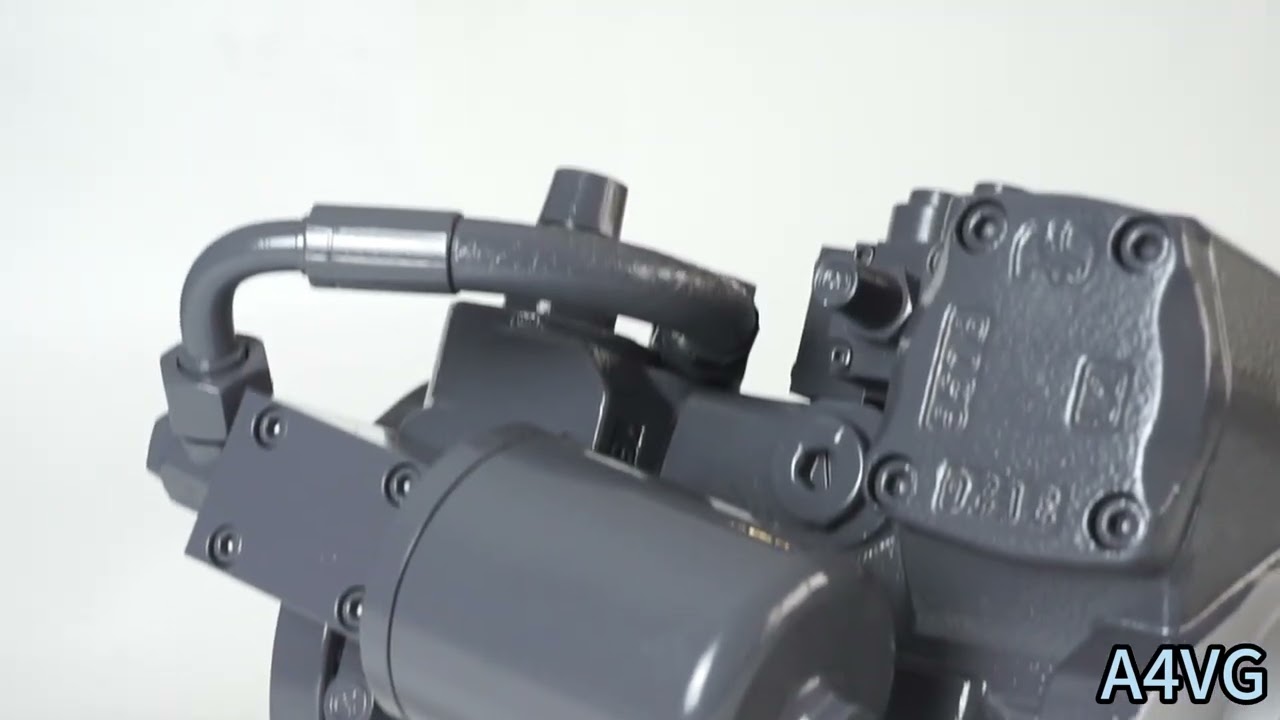
Vg الإزاحة لكل دورة في [سم3] Δp Differential pressure [bar] n Rotational speed [rpm] ηv Volumetric efficiency ηhm Hydraulic-mechanical efficiency ηt الكفاءة الكلية (ηt= ηv*ηhm) 1) The values are applicable: – for the optimum viscosity range from n =36 to 16mm2/s – for hydraulic fluid based on mineral oils (for HF hydraulic fluids,observe the technical data in 90225) 2)Valid at half corner power (e.g.at Vجي ماكس and p,/2) 3) Valid at Δp=70 to 150 bar or Δp < 300 bar and t<0.1s 4) Without boost pump 5) The data are valid for values between the minimum required and maximum permissible rotational speed.Valid for external excitation (e.g.diesel engine 2 to 8 times rotary frequency,cardan shaft twice the rotar frequency). The limit value is only valid for a single pump. The load capacity of the connection parts must be considered.Watch A4VG Product Video
Related Selection Resources
Request a A4VG Quotation
أخبرنا بالتكوين المطلوب، الكمية والتطبيق.
المنتجات ذات الصلة
Compare related hydraulic pumps and confirm the complete configuration for your application.

اكتب رمزاً
| 01 | 02 | 03 | 04 | 05 | 06 | 07 | 08 | 09 | 10 | 11 | 12 | 13 | 14 | 15 | 16 | 17 | 18 | 19 | 20 | 21 | 22 | ||
| A4V | G | D | / | 32 | - | N |
وحدة مكبس محوري
| 01 | تصميم لوحة مائلة، متغير، الضغط الاسمي 400 بار، الضغط الأقصى 450 بار | A4V |
نمط التشغيل
| 02 | مضخة، دائرة مغلقة | G |
المقاس (NG)
| 03 | الإزاحة الهندسية، انظر "البيانات الفنية" في الصفحة 8 | 28 | 40 | 56 | 71 | 90 | 125 | 180 |
جهاز تحكم
| 28 | 40 | 56 | 71 | 90 | 125 | 180 | |||||
| 04 | بدون وحدة تحكم | ● | ● | ● | ● | ● | ● | ● | إن في | ||
| تحكم تناسبي، هيدروليكي | الضغط المرتبط بضغط الإرشاد p = من 6 إلى 18 بار | ● | ● | ● | ● | ● | ● | ● | HD3 | ||
| مؤازر ميكانيكي | ● | ● | ● | ● | ● | ● | ● | واجب منزلي | |||
| تحكم نسبي، كهربائي | الجهد = 12 فولت | ● | ● | ● | ● | ● | ● | ● | الحلقة 3 | ||
| الجهد = 24 فولت | ● | ● | ● | ● | ● | ● | ● | الحلقة الرابعة | |||
| تحكم بنقطتين، كهربائي | الجهد = 12 فولت | ● | ● | ● | ● | ● | ● | ● | إي زي 1 | ||
| الجهد = 24 فولت | ● | ● | ● | ● | ● | ● | ● | EZ2 | |||
| تحكم آلي، متعلق بالسرعة | الجهد = 12 فولت | ● | ● | ● | ● | ● | ● | ● | DA1 | ||
| الجهد = 24 فولت | ● | ● | ● | ● | ● | ● | ● | DA2 | |||
| تحكم هيدروليكي، تشغيل مباشر | ● | ● | ● | ● | ● | ● | ● | دي جي | |||
| تحكم كهربائي، تشغيل مباشر،,
صمامان خافضان للضغط |
الجهد = 12 فولت | ● | ● | ● | ● | - | - | - | إي تي 5 | ||
| الجهد = 24 فولت | ● | ● | ● | ● | - | - | - | إي تي 6 | |||
قطع الضغط
| 05 | قطع الضغط (قياسي) | D |
مفتاح الوضع المحايد
| 06 | بدون مفتاح وضع حيادي (بدون رمز) | ● | |
| مفتاح الوضع المحايد (للتحكم في الأجهزة فقط) | ● | L |
محدد الشوط الميكانيكي
| 07 | بدون محدث شوط ميكانيكي (بدون رمز) | ● | |
| محدد شوط ميكانيكي، قابل للتعديل من الخارج | ● | M |
منفذ ضغط غرفة الشوط
| 06 | بدون ضغط منفذ ضغط حجرة (إكس)3, ، X4 بدون رمز | ● | |
| منفذ ضغط غرفة الشوط X3, ، X4 | ● | T |
صمام تحكم مزدوج الفعل
| إن في | عالي الدقة | واجب منزلي | دي جي | دا | إي بي | سهل | ||||
| 09 | بدون صمام تحكم DA | ● | ● | ● | ● | - | ● | ● | 1 | |
| صمام تحكم مزدوج الفعل، إعداد ثابت | - | ● | ● | ● | ● | ● | - | 2 | ||
| صمام تحكم مزدوج الفعل، قابل للتعديل ميكانيكياً مع ذراع تحديد الموقع | اتجاه التشغيل، في اتجاه عقارب الساعة | - | ● | ● | ● | ● | ● | - | ٣ آر | |
| اتجاه التشغيل,
عكس عقارب الساعة |
- | ● | ● | ● | ● | ● | - | 3L | ||
| صمام تحكم مزدوج الفعل، إعداد ثابت، فتحات لجهاز التحكم التجريبي | - | ● | ● | - | ● | ● | - | 7 | ||
| صمام تحكم مزدوج الفعل (DA)، إعداد ثابت، وصمام تعشيق مكابح مثبت، يُتحكم فيه بسائل الفرامل | بناءً على الزيوت المعدنية | - | - | - | - | ● | - | - | 8 | |
•= متوفر ○= عند الطلب -= غير متوفر  البرنامج المفضل
مسلسل
| 10 | المسلسل 3، الفهرس 2 | 32 |
اتجاه الدوران
| 11 | من نهاية العمود | مع عقارب الساعة | R |
| عكس عقارب الساعة | L |
مادة مانعة للتسرب
| 12 | مانع تسرب عمود من مطاط النيتريل (NBR)، مانع تسرب عمود من الفلوروەلاستومر (FKM) | N |
عمود الدوران
| 28 | 40 | 56 | 71 | 90 | 125 | 180 | ||||
| 13 | عمود مسنن
DIN 5480 |
لمضخة واحدة | ● | ● | ● | ● | ● | ● | ● | Z |
| لمضخة الدمج - المضخة الأولى | _1) | ● | ● | ● | ● | ● | _2) | A | ||
| عمود مسنن
ANSI B92.1a |
لمضخة واحدة | ● | ● | ● | ● | ● | ● | ● | S | |
| لمضخة الدمج - المضخة الأولى | _2) | _2) | ● | ● | _2) | ● | ● | T | ||
| للمضخة المشتركة - المضخة الثانية | - | ● | - | - | ● | - | - | U |
شفة التركيب
| 28 | 40 | 56 | 71 | 90 | 125 | 180 | ||||
| 14 | SAE J744 | ثقبان | ● | ● | ● | - | - | - | - | C |
| ذو 4 ثقوب | - | - | - | - | - | - | ● | D | ||
| 2+4 فتحات | - | - | - | ● | ● | ● | - | F |
منفذ عامل
| 28 | 40 | 56 | 71 | 90 | 125 | 180 | ||||
| 15 | منفذا العمل SAE A و B، العلوي والسفلي | منفذ الشفط S السفلي | - | ● | ● | ● | ● | ● | ● | 02 |
| منفذا العمل SAE A و B، العلوي والسفلي | منفذ الشفط S العلوي | - | ● | ● | ○ | ○ | ○ | ○ | 03 | |
| منفذ العمل SAE A و B، نفس الجانب الأيمن3) | منفذ الشفط S السفلي | ● | - | - | - | - | - | - | 10 | |
| ميناء العمل SAE A و B، نفس الجانب الأيسر3) | منفذ الشفط S السفلي | - | - | - | ● | ○ | ● | - | ||
| منفذ العمل SAE A و B، نفس الجانب الأيمن3) | منفذ الشفط S العلوي | - | - | - | ○ | ○ | ○ | - | 13 | |
| ميناء العمل SAE A و B، نفس الجانب الأيسر3) | منفذ الشفط S العلوي | ● | - | ● | - | - | - | - |
مضخة تعزيز
| 16 | بدون مضخة تعزيز مدمجة | بدون محرك مرور | N |
| مع قيادة من خلال | K | ||
| مضخة تعزيز مدمجة | مع وبدون قيادة من خلال | F |
من خلال القيادة
| 28 | 40 | 56 | 71 | 90 | 125 | 180 | ||||
| 17 | بدون قيادة من خلال، الإصدارات N و F فقط (رقم 16) | ● | ● | ● | ● | ● | ● | ● | 00 | |
| فلنج SAE J7444) | سرّة لعمود مسنن | |||||||||
| 82-2(أ) | نصف بوصة 9T 16/32DP5) | ● | ● | ● | ● | ● | ● | ● | 01 | |
| 101-2(ب) | ثمن بوصة 13T 16/32DP5) | ● | ● | ● | ● | ● | ● | ● | 02 | |
| بوصة واحدة 15T 16/32DP5) | ● | ● | ● | ● | ● | ● | ● | 04 | ||
| 127-2(ج) | بوصة واحدة 15T 16/32DP5) | - | ● | - | - | - | - | - | 09 | |
| بوصة واحدة 1 1/4 14T 12/24DP5) | - | - | ● | ● | ● | ● | ● | 07 | ||
| 52-2/4(د) | W35 2X16X9g7) | - | - | - | - | ● | - | - | 73 | |
| بوصة واحدة 1 3/4 13T 8/16DP5) | - | - | - | - | - | ● | ● | 69 | ||
| 165-4(هـ) | بوصة واحدة 1 3/4 13T 8/16DP5) | - | - | - | - | - | - | ● | 72 | |
•= متوفر ○= عند الطلب -= غير متوفر
1) المعيار للمضخة المجمعة - المضخة الأولى: عمود Z
2) معيار للمضخة المجمعة - المضخة الأولى: عمود S
3) ممكن فقط بدون مرشح ملحق
4)2=ثقبين;4=أربعة ثقوب
5) محور للعمود المسنن وفقًا لـ ANSI B92.1a
6) NG90 إلى 180 مع حافة ذات أربعة ثقوب إضافية (127-4)
7) محور للعمود المسنن وفقًا لـ DIN 5480.
صمام تخفيف الضغط العالي
| نسبة الضبط Δp | 28 | 40 | 56 | 71 | 90 | 125 | 180 | ||||
| 18 | صمام تخفيف الضغط العالي، يعمل بالتحكم التجريبي | 100 إلى 420 بار | مع تجاوز | - | - | - | ● | ● | ● | ● | 1 |
| صمام تخفيف الضغط العالي، يعمل بمحرك مباشر، ضبط ثابت | 250 إلى 420 بار | بدون تجاوز | ● | ● | ● | - | - | - | - | 3 | |
| مع تجاوز | ● | ● | ● | - | - | - | - | 5 | |||
| 100 إلى 250 بار | بدون تجاوز | ● | ● | ● | - | - | - | - | 4 | ||
| مع تجاوز | ● | ● | ● | - | - | - | - | 6 | |||
دائرة تعزيز الترشيح / إمداد ضغط التعزيز الخارجي
| 28 | 40 | 56 | 71 | 90 | 125 | 180 | |||
| 19 | الترشيح في خط شفط مضخة التعزيز | ● | ● | ● | ● | ● | ● | ● | S |
| الترشيح في خط ضغط مضخة التعزيز
فتحة لدائرة تعزيز الترشيح الخارجية (Fe و Fa) |
● | ● | ● | ● | ● | ● | ● | D | |
| مرشح الملحق مع صمام بدء بارد | - | ● | ● | ● | ● | ● | ● | F | |
| مرشح الملحق مع صمام بدء بارد ومؤشر تلوث بصري | - | ● | ● | ● | ● | ● | ● | P | |
| مرشح الملحق مع صمام بدء بارد ومؤشر تلوث كهربائي | - | ● | ● | ● | ● | ● | ● | B | |
| توريد ضغط تعزيز خارجي (نسخة بدون مضخة تعزيز مدمجة - N00، K...) | ● | ● | ● | ● | ● | ● | ● | E |
مستشعر زاوية الدوران
| 28 إلى 180 | |||
| 20 | بدون مستشعر زاوية الدوران (بدون رمز) | ● | |
| مستشعر زاوية الدوران الكهربائي8) | ● | R |
موصل للملفات اللولبية9)
| 28 إلى 180 | ||||
| 21 | بدون موصل (بدون رمز)، فقط للتحكم الهيدروليكي البحت | ● | ||
| موصل مصبوب من ديوتش، 2 دبوس | بدون صمام ثنائي للحماية من الجهد الزائد | ● | P | |
| مع صمام ثنائي للحماية من الجهد الزائد (لـ EZ وDA فقط) | ● | Q | ||
الإصدار القياسي/الخاص
| 22 | الإصدار القياسي | بدون رمز | |
| مُدمج مع جزء ملحق أو مضخة ملحقة | -K | ||
| الإصدار الخاص | -S | ||
| مُدمج مع جزء ملحق أو مضخة ملحقة | -SK |
• = متوفر ○ = عند الطلب - = غير متوفر البرنامج المفضل
ملاحظة
▶ بالإضافة إلى رمز النوع، يُرجى تحديد
البيانات الفنية ذات الصلة عند تقديم طلبكم.
8)يُرجى الاتصال بنا إذا تم استخدام مستشعر زاوية الدوران للتحكم
9) قد تختلف موصلات المكونات الكهربائية الأخرى.
البيانات الفنية
| حجم
الإزاحة الهندسية لكل دورة |
غير مقبول | 28 | 40 | 56 | 71 | 90 | 125 | 180 | |||
| مضخة متغيرة الإزاحة | Vجي ماكس | سم3 | 28 | 40 | 56 | 71 | 90 | 125 | 180 | ||
| مضخة تعزيز (عند ضغط p=20 بار) | VgSp | سم3 | 6.1 | 8.6 | 11.6 | 19.6 | 19.6 | 28.3 | 39.8 | ||
| سرعة الدوران1) | الحد الأقصى عند Vجي ماكس | nالاسمية | دورة في الدقيقة | 4250 | 4000 | 3600 | 3300 | 3050 | 2850 | 2500 | |
| محدود، أقصى2) | nالأقصى 1 | دورة في الدقيقة | 4500 | 4200 | 3900 | 3600 | 3300 | 3250 | 2900 | ||
| متقطع، أقصى3) | nالأقصى 2 | دورة في الدقيقة | 5000 | 5000 | 4500 | 4100 | 3800 | 3450 | 3000 | ||
| الحد الأدنى | nالحد الأدنى | دورة في الدقيقة | 500 | 500 | 500 | 500 | 500 | 500 | 500 | ||
| تدفق | عند nالاسمية و Vجي ماكس | qv | لتر/دقيقة | 119 | 160 | 202 | 234 | 275 | 356 | 450 | |
| طاقة4) | عند nالاسمية,Vجي ماكس و Δp = 400 بار | P | كيلوواط | 79 | 107 | 134 | 156 | 183 | 238 | 300 | |
| عزم الدوران4) | عند Vجي ماكس و | Δp = 440 بار | T | لا شيء جديد | 178 | 255 | 357 | 452 | 573 | 796 | 1146 |
| Δp = 100 بار | T | لا شيء جديد | 45 | 64 | 89 | 113 | 143 | 199 | 286 | ||
| صلابة الدوران لعمود القيادة | S | c | ك.ن.م/راديان | 31.4 | 69 | 80.8 | 98.8 | 158.1 | 218.3 | 244.5 | |
| T | c | ك.ن.م/راديان | - | - | 95 | 120.9 | - | 252.1 | 318.4 | ||
| A | c | ك.ن.م/راديان | - | 79.6 | 95.8 | 142.4 | 176.8 | 256.5 | - | ||
| Z | c | ك.ن.م/راديان | 32.8 | 67.5 | 78.8 | 122.8 | 137 | 223.7 | 319.6 | ||
| U | c | ك.ن.م/راديان | - | 50.8 | - | - | 107.6 | - | - | ||
| عزم القصور الذاتي للمجموعة الدوارة | JTW | كجم.م2 | 0.0022 | 0.0038 | 0.0066 | 0.0097 | 0.0149 | 0.0232 | 0.0444 | ||
| التسارع الزاوي الأقصى5) | α | راديان/ثانية2 | 38000 | 30000 | 24000 | 21000 | 18000 | 14000 | 11000 | ||
| حجم الحالة | V | L | 0.9 | 1.1 | 1.5 | 1.3 | 1.5 | 2.1 | 3.1 | ||
| الوزن (بدون القيادة عبر) تقريبًا. | m | kg | 29 | 31 | 38 | 50 | 60 | 80 | 101 | ||
ملاحظة
▶القيم النظرية، بدون الكفاءة والتحملات؛ القيم مقربة
▶التشغيل فوق القيم القصوى أو أقل من القيم الدنيا قد يؤدي إلى فقدان الوظيفة، تقليل عمر الخدمة أو تدمير وحدة المكبس المحوري.
تحديد خصائص التشغيل
| تدفق | qv=(Vg ∙ n ∙ ηv) / 1000 | لتر/دقيقة |
| عزم الدوران | T=(Vg ∙ Δp) / 20 ∙ π ∙ ηhm | لا شيء جديد |
| طاقة | P=(2π ∙ T ∙ n)/60000=(qv ∙ Δp)/600 ∙ ηt | كيلوواط |
مفتاح
Vg الإزاحة لكل دورة في [سم3]
Δp ضغط تفاضلي [بار]
n Rotational speed [rpm]
ηv الكفاءة الحجمية
ηhm الكفاءة الهيدروليكية الميكانيكية
ηt الكفاءة الكلية (ηt= ηv*ηhm)
1) القيم تنطبق:
- for the optimum viscosity range from n =36 to 16mm2/s
- for hydraulic fluid based on mineral oils (for HF hydraulic fluids,observe the technical data in 90225)
2)Valid at half corner power (e.g.at Vجي ماكس and p,/2)
3) Valid at Δp=70 to 150 bar or Δp < 300 bar and t<0.1s
4) Without boost pump
5) The data are valid for values between the minimum required and maximum permissible rotational speed.Valid for external excitation (e.g.diesel engine 2 to 8 times rotary frequency,cardan shaft twice the rotar frequency).
The limit value is only valid for a single pump.
The load capacity of the connection parts must be considered.
