Wenzhou Prance Hydraulic Equipment Co., Ltd.


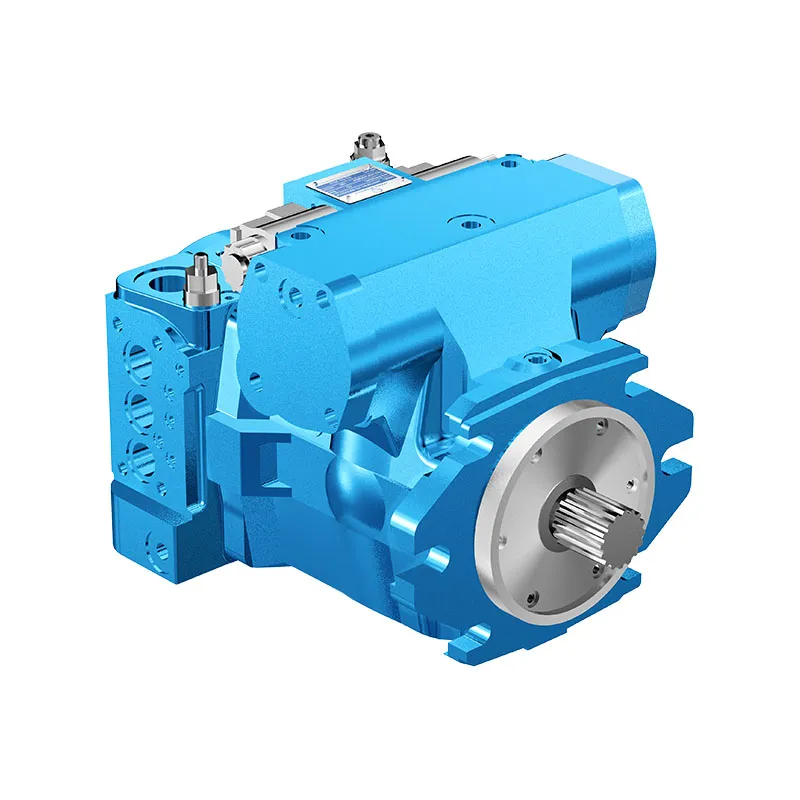
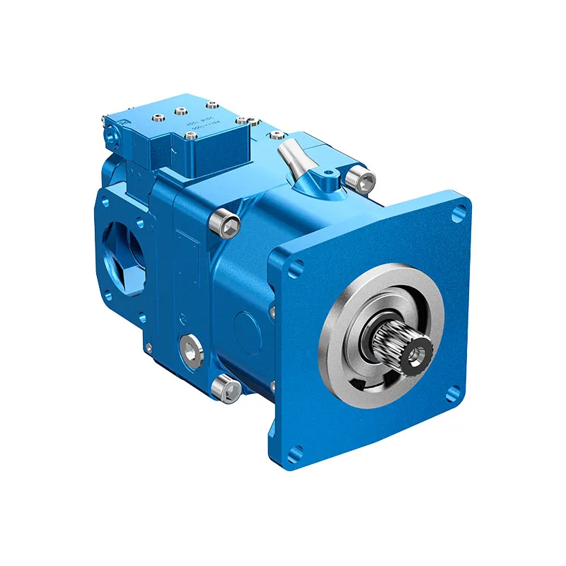
A4VG Closed Circuit Variable Piston Pump
The A4VG variable displacement pump is offered for closed-circuit hydraulic drives. The boost supply, high-pressure loop and control arrangement form one selection problem, especially where a drive reverses or sees an overrunning load.
- Integrated boost and pilot supply
- Reversible flow through neutral
- High-pressure relief functions
- Pressure cut-off configuration
PRANCE HYDRAULIC · PRODUCT SERIES
A4VG Closed Circuit Variable Piston Pump
Axial piston; variable swashplate · Closed circuit
The A4VG variable displacement pump is offered for closed-circuit hydraulic drives. The boost supply, high-pressure loop and control arrangement form one selection problem, especially where a drive reverses or sees an overrunning load.
Model
✓
Request a QuotationTechnische Daten & Datenblatt anzeigenA4VGAxial piston; variable swashplate
Confirm the complete model and approved specification with Prance Hydraulic. Product-series references alone do not establish interchangeability.
Configuration review · Technical documentation · Product selection
Produktdetails
- Integrated boost and pilot supply
- Reversible flow through neutral
- High-pressure relief functions
- Pressure cut-off configuration
CATEGORIES: Kolbenpumpe, Verstellpumpe
A4VG Features & Application
Integrated boost and pilot supply
Account for pilot or replenishment demand and the relevant pressure limits. Include filtration and the return or drain route in the circuit review.
Reversible flow through neutral
Review combined drive torque and simultaneous demand, including any additional pump connected to the drive.
High-pressure relief functions
Keep continuous, intermittent and peak conditions separate. Use the row for the selected size and configuration.
Pressure cut-off configuration
Keep continuous, intermittent and peak conditions separate. Use the row for the selected size and configuration.
A4VG Specifications
| Series / model | A4VG |
|---|---|
| Product type | A4VG Closed Circuit Variable Piston Pump |
| Design | Axial piston; variable swashplate |
| Circuit / selection | Closed circuit |
| Published nominal sizes | 28, 40, 56, 71, 90, 125 and 180 |
| Schaltkreis | Closed circuit |
A4VG Selection & Configuration
The A4VG variable displacement pump is offered for closed-circuit hydraulic drives. The boost supply, high-pressure loop and control arrangement form one selection problem, especially where a drive reverses or sees an overrunning load.
Check pressure cut-off, high-pressure relief and boost-pressure settings separately. Provide the motor, flushing demand, maximum drive speed and control signal. Confirm the model series and through-drive requirements before comparing another A4VG or AA4VG unit.

cURL Too many subrequests by single Worker invocation. To configure this limit, refer to https://developers.cloudflare.com/workers/wrangler/configuration/#limits.
cURL Too many subrequests by single Worker invocation. To configure this limit, refer to https://developers.cloudflare.com/workers/wrangler/configuration/#limits.
Hydraulic pumps · Hydraulic motors · Hydraulic valves
Send the MS nameplate, operating requirements and installation drawing for a configuration review before quoting.
- Model review — send the full model code or an existing nameplate photograph.
- Interface matching — confirm shaft, mounting flange, rotation and ports.
- Operating conditions — provide flow, pressure, speed, fluid and duty cycle.
- Documentation — request the relevant product data and drawings for your review.

A4VG Buying Guide
Use this sequence to prepare the A4VG configuration for review and quotation.
- Define required flow at the actual drive speed and continuous pressure.
- Identify peak pressure, duration and the work cycle.
- Confirm the selected displacement control and any auxiliary-drive requirement.
- Match rotation viewed from the shaft end, shaft, flange and ports.
- Review inlet conditions, drain routing and the installation envelope.
- Confirm fluid, viscosity, temperature, filtration and seals.
- Approve the complete model, control, drawing, quantity and delivery terms.

Selection, Documentation & Project Support

Selection Support
Learn more →Share your hydraulic circuit, operating point and installation requirements for a configuration discussion.
Flow · Pressure · Speed · Interfaces

Technical Resources
Learn more →Review product documentation, model codes and technical data before finalizing the specification.
Datasheets · Model codes · Drawings

Project Inquiries
Learn more →Send your required model, quantity, application and project requirements to discuss your inquiry.
Product inquiries · Configuration review
Configuration, Quantity & Delivery
Confirm the complete MS code, approved drawing and operating limits. Availability, quantity, documentation and delivery date are confirmed in the quotation.
Discuss Your A4VG Application
Send the full model code, operating duty, installation details and quantity.
Request a A4VG QuotationA4VG Questions Before Ordering
What type of product is the A4VG?
A4VG Closed Circuit Variable Piston Pump. Design: Axial piston; variable swashplate. Closed circuit. Confirm the complete order code for the offered version.
Can a similar pump replace the A4VG?
cURL Too many subrequests by single Worker invocation. To configure this limit, refer to https://developers.cloudflare.com/workers/wrangler/configuration/#limits.
cURL Too many subrequests by single Worker invocation. To configure this limit, refer to https://developers.cloudflare.com/workers/wrangler/configuration/#limits
Define required flow at the actual drive speed and continuous pressure. Identify peak pressure, duration and the work cycle. Attach the nameplate, complete order code, installation drawing and required quantity.
A4VG Technical Data & Documents
View A4VG catalog data and operating conditions
cURL Too many subrequests by single Worker invocation. To configure this limit, refer to https://developers.cloudflare.com/workers/wrangler/configuration/#limits.
Technische Daten
| Size Displacement.geometric.per revolution | NG | 28 | 40 | 56 | 71 | 90 | 125 | 180 | |||
| Verstellpumpe | VG-Max | cm3 | 28 | 40 | 56 | 71 | 90 | 125 | 180 | ||
| Tanksanhebung (bei p=20bar) | VgSp | cm3 | 6.1 | 8.6 | 11.6 | 19.6 | 19.6 | 28.3 | 39.8 | ||
| Drehzahl1) | Maximum bei VG-Max | nnom | U/min | 4250 | 4000 | 3600 | 3300 | 3050 | 2850 | 2500 | |
| begrenzt, maximal2) | nmax1 | U/min | 4500 | 4200 | 3900 | 3600 | 3300 | 3250 | 2900 | ||
| intermittierend, maximal3) | nmax2 | U/min | 5000 | 5000 | 4500 | 4100 | 3800 | 3450 | 3000 | ||
| Minimum | nmin. | U/min | 500 | 500 | 500 | 500 | 500 | 500 | 500 | ||
| Drehmoment4) | bei VG-Max und | Δp = 440 bar | T | Machs gut | 178 | 255 | 357 | 452 | 573 | 796 | 1146 |
| Δp = 100 bar | T | Machs gut | 45 | 64 | 89 | 113 | 143 | 199 | 286 | ||
| Verdrehsteifigkeit der Antriebswelle | S | c | kNm/rad | 31.4 | 69 | 80.8 | 98.8 | 158.1 | 218.3 | 244.5 | |
| T | c | kNm/rad | – | – | 95 | 120.9 | – | 252.1 | 318.4 | ||
| A | c | kNm/rad | – | 79.6 | 95.8 | 142.4 | 176.8 | 256.5 | – | ||
| Z | c | kNm/rad | 32.8 | 67.5 | 78.8 | 122.8 | 137 | 223.7 | 319.6 | ||
| U | c | kNm/rad | – | 50.8 | – | – | 107.6 | – | – | ||
| Trägheitsmoment der Drehgruppe | JTW | Kgm2 | 0.0022 | 0.0038 | 0.0066 | 0.0097 | 0.0149 | 0.0232 | 0.0444 | ||
| Maximale Winkelbeschleunigung5) | α | rad/s2 | 38000 | 30000 | 24000 | 21000 | 18000 | 14000 | 11000 | ||
| Fallzahl | V | L | 0.9 | 1.1 | 1.5 | 1.3 | 1.5 | 2.1 | 3.1 | ||
| Gewicht (ohne Durchtrieb) ca. | m | kg | 29 | 31 | 38 | 50 | 60 | 80 | 101 | ||
Hinweis
▶Theoretical values, without efficiency and tolerances;values rounded ▶Operation above the maximum values or below the minimum values may result in a loss of function, a reduced service life or in the destruction of the axial piston unit.Bestimmung der Betriebskennwerte
Schlüssel
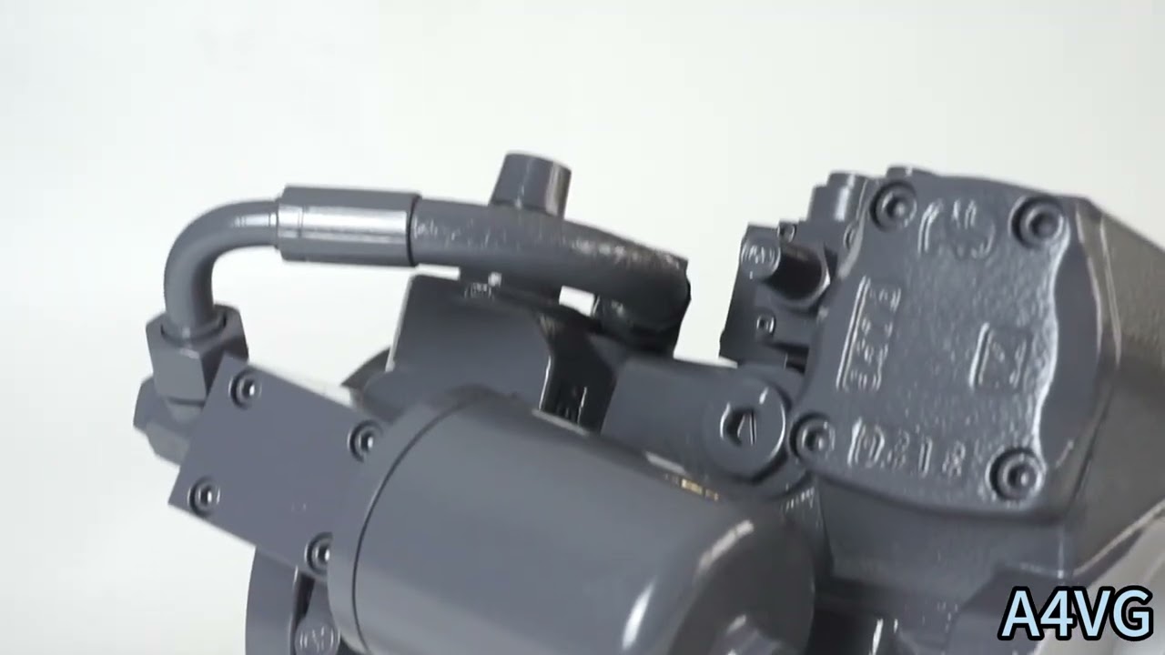
Vg Fördervolumen pro Umdrehung in [cm3] Δp Differential pressure [bar] n Rotational speed [rpm] ηv Volumetric efficiency ηhm Hydraulic-mechanical efficiency ηt Gesamtwirkungsgrad (ηt= ηv*ηhm) 1) The values are applicable: – for the optimum viscosity range from n =36 to 16mm2/s – for hydraulic fluid based on mineral oils (for HF hydraulic fluids,observe the technical data in 90225) 2)Valid at half corner power (e.g.at VG-Max and p,/2) 3) Valid at Δp=70 to 150 bar or Δp < 300 bar and t<0.1s 4) Without boost pump 5) The data are valid for values between the minimum required and maximum permissible rotational speed.Valid for external excitation (e.g.diesel engine 2 to 8 times rotary frequency,cardan shaft twice the rotar frequency). The limit value is only valid for a single pump. The load capacity of the connection parts must be considered.Watch A4VG Product Video
Related Selection Resources
Request a A4VG Quotation
Tell us your required configuration, quantity and application.
Ähnliche Produkte
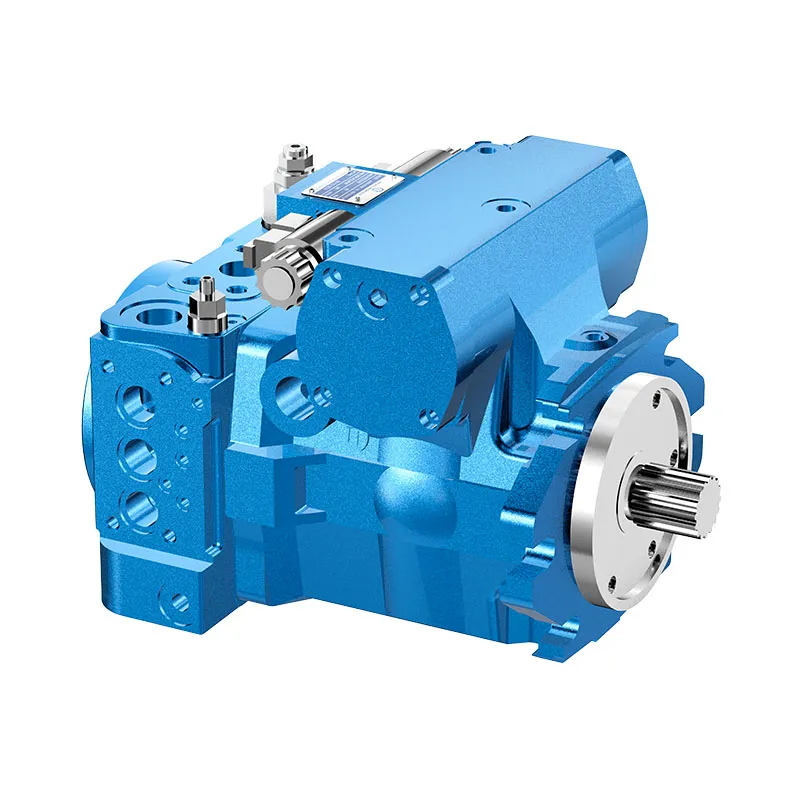
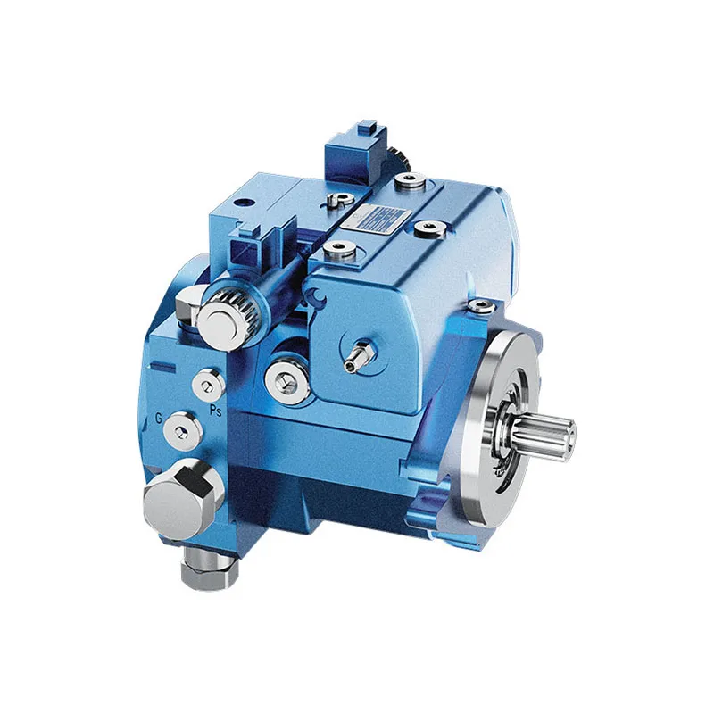
Compare related hydraulic pumps and confirm the complete configuration for your application.

Code eingeben
| 01 | 02 | 03 | 04 | 05 | 06 | 07 | 08 | 09 | 10 | 11 | 12 | 13 | 14 | 15 | 16 | 17 | 18 | 19 | 20 | 21 | 22 | ||
| A4V | G | D | / | 32 | - | N |
Axialkolbeneinheit
| 01 | Schrägscheibenbauweise, verstellbar, Nenndruck 400 bar, Maximaldruck 450 bar | A4V |
Betriebsart
| 02 | Pumpe, geschlossener Kreislauf | G |
Größe (NG)
| 03 | Geometrisches Verdrängungsvolumen, siehe "Technische Daten" auf Seite 8 | 28 | 40 | 56 | 71 | 90 | 125 | 180 |
Steuergerät
| 28 | 40 | 56 | 71 | 90 | 125 | 180 | |||||
| 04 | Ohne Steuergerät | ● | ● | ● | ● | ● | ● | ● | NV | ||
| Proportionalregelung, hydraulisch | Steuerdruckabhängig p = 6 bis 18 bar | ● | ● | ● | ● | ● | ● | ● | HD3 | ||
| Mechanischer Servo | ● | ● | ● | ● | ● | ● | ● | HW | |||
| Proportionalregelung, elektrisch | U=12V | ● | ● | ● | ● | ● | ● | ● | EP3 | ||
| U=24V | ● | ● | ● | ● | ● | ● | ● | EP4 | |||
| Zweipunktregelung, elektrisch | U=12V | ● | ● | ● | ● | ● | ● | ● | EZ1 | ||
| U=24V | ● | ● | ● | ● | ● | ● | ● | EZ2 | |||
| Automatische Steuerung, drehzahlabhängig | U=12V | ● | ● | ● | ● | ● | ● | ● | DA1 | ||
| U=24V | ● | ● | ● | ● | ● | ● | ● | DA2 | |||
| direktgesteuerte Hydrauliksteuerung | ● | ● | ● | ● | ● | ● | ● | DG | |||
| Elektrische Steuerung, direktgesteuert,
zwei Druckminderer |
U=12V | ● | ● | ● | ● | - | - | - | ET5 | ||
| U=24V | ● | ● | ● | ● | - | - | - | ET6 | |||
Druckabschaltung
| 05 | Druckabschaltung (Standard) | D |
Neutralpositionsschalter
| 06 | Ohne Neutralstellungsschalter (ohne Code) | ● | |
| Neutralpositionsschalter (nur für HW-Steuerung) | ● | L |
Mechanischer Hubbegrenzer
| 07 | Ohne mechanischen Hubbegrenzer (ohne Code) | ● | |
| Mechanischer Hubbegrenzer, extern einstellbar | ● | M |
Hubkammerdruckanschluss
| 06 | Ohne Beaufschlagung des Steuerkammerdruckanschlusses X3, X4 ohne Code | ● | |
| Kolbenstangenseitiger Druckanschluss X3, X4 | ● | T |
DA-Regelventil
| NV | HD | HW | DG | DA | EP | EZ | ||||
| 09 | Ohne DA-Steuerventil | ● | ● | ● | ● | - | ● | ● | 1 | |
| DA-Regelventil, Festeinstellung | - | ● | ● | ● | ● | ● | - | 2 | ||
| DA-Steuerventil, mechanisch einstellbar mit Stellhebel | Betätigungsrichtung, im Uhrzeigersinn | - | ● | ● | ● | ● | ● | - | 3R | |
| Betätigungsrichtung,
gegen den Uhrzeigersinn |
- | ● | ● | ● | ● | ● | - | 3L | ||
| DA-Steuerventil, Festwert, Anschlüsse für Vorsteuergerät | - | ● | ● | - | ● | ● | - | 7 | ||
| DA-Steuerventil, feste Einstellung und Bremsinchventil angebaut, Betätigung mit Bremsflüssigkeit | auf Mineralölbasis | - | - | - | - | ● | - | - | 8 | |
• = verfügbar ○ = auf Anfrage - = nicht verfügbar  = bevorzugtes Programm
Serie
| 10 | Reihe 3, Index 2 | 32 |
Drehrichtung
| 11 | Ansicht vom Wellenende | im Uhrzeigersinn | R |
| gegen den Uhrzeigersinn | L |
Dichtungsmaterial
| 12 | NBR (Nitrilkautschuk), Wellendichtring aus FKM (Fluorelastomer) | N |
Antriebswelle
| 28 | 40 | 56 | 71 | 90 | 125 | 180 | ||||
| 13 | Kerbwelle
DIN 5480 |
für eine einzelne Pumpe | ● | ● | ● | ● | ● | ● | ● | Z |
| für Kombipumpe - 1. Pumpe | _1) | ● | ● | ● | ● | ● | _2) | A | ||
| Kerbwelle
ANSI B92.1a |
für eine einzelne Pumpe | ● | ● | ● | ● | ● | ● | ● | S | |
| für Kombipumpe - 1. Pumpe | _2) | _2) | ● | ● | _2) | ● | ● | T | ||
| für Verbundpumpe-2. Pumpe | - | ● | - | - | ● | - | - | U |
Montageflansch
| 28 | 40 | 56 | 71 | 90 | 125 | 180 | ||||
| 14 | SAE J744 | 2-Loch | ● | ● | ● | - | - | - | - | C |
| 4-Loch | - | - | - | - | - | - | ● | D | ||
| 2+4-Loch | - | - | - | ● | ● | ● | - | F |
Funktionierender Port
| 28 | 40 | 56 | 71 | 90 | 125 | 180 | ||||
| 15 | SAE-Arbeitsanschluss A und B, oben und unten | Absaugstutzen S unten | - | ● | ● | ● | ● | ● | ● | 02 |
| SAE-Arbeitsanschluss A und B, oben und unten | Absauganschluss S oben | - | ● | ● | ○ | ○ | ○ | ○ | 03 | |
| SAE-Arbeitsanschluss A und B, beide auf der rechten Seite3) | Absaugstutzen S unten | ● | - | - | - | - | - | - | 10 | |
| SAE-Arbeitsanschluss A und B, gleiche Seite links3) | Absaugstutzen S unten | - | - | - | ● | ○ | ● | - | ||
| SAE-Arbeitsanschluss A und B, beide auf der rechten Seite3) | Absauganschluss S oben | - | - | - | ○ | ○ | ○ | - | 13 | |
| SAE-Arbeitsanschluss A und B, gleiche Seite links3) | Absauganschluss S oben | ● | - | ● | - | - | - | - |
Kraftstoffförderpumpe
| 16 | Ohne integrierte Ladedruckpumpe | ohne Durchgangsantrieb | N |
| mit Durchtrieb | K | ||
| Integrierte Ladedruckpumpe | mit und ohne Durchtrieb | F |
Durchfahrt
| 28 | 40 | 56 | 71 | 90 | 125 | 180 | ||||
| 17 | Ohne Durchtrieb, nur Ausführungen N und F (Nr. 16) | ● | ● | ● | ● | ● | ● | ● | 00 | |
| SAE-J744-Flansch4) | Nabe für Keilwelle | |||||||||
| 82-2(A) | 5/8 in 9T 16/32DP5) | ● | ● | ● | ● | ● | ● | ● | 01 | |
| 101-2(B) | 7/8 in 13T 16/32DP5) | ● | ● | ● | ● | ● | ● | ● | 02 | |
| 1 in 15T 16/32DP5) | ● | ● | ● | ● | ● | ● | ● | 04 | ||
| 127-2(C) | 1 in 15T 16/32DP5) | - | ● | - | - | - | - | - | 09 | |
| 1 1/4 in 14T 12/24DP5) | - | - | ● | ● | ● | ● | ● | 07 | ||
| 52-2/4(D) | W35 2X16X9g7) | - | - | - | - | ● | - | - | 73 | |
| 1 3/4 in 13T 8/16DP5) | - | - | - | - | - | ● | ● | 69 | ||
| 165-4(E) | 1 3/4 in 13T 8/16DP5) | - | - | - | - | - | - | ● | 72 | |
• = verfügbar ○ = auf Anfrage - = nicht verfügbar
1) Standard für Kombinationspumpe – 1. Pumpe: Welle Z
2) Standard für Kombinationspumpe - 1. Pumpe: Welle S
3) Nur ohne Anhangsfilter möglich
4)2=2-Loch;4=4-Loch
5) Nabe für Passbzw. Kerbverzahnung nach ANSI B92.1a
6) NG90 bis 180 mit zusätzlichem 4-Loch-Flansch (127-4)
7) Nabe für Passverzahnung nach DIN 5480.
Hochdruck-Sicherheitsventil
| Einstellung rabe Δp | 28 | 40 | 56 | 71 | 90 | 125 | 180 | ||||
| 18 | Vorgesteuertes Hochdruck-Sicherheitsventil | 100 bis 420 bar | mit Bypass | - | - | - | ● | ● | ● | ● | 1 |
| Hochdruck-Entlastungsventil, direktgesteuert, fest eingestellt | 250 bis 420 bar | ohne Bypass | ● | ● | ● | - | - | - | - | 3 | |
| mit Bypass | ● | ● | ● | - | - | - | - | 5 | |||
| 100 bis 250 bar | ohne Bypass | ● | ● | ● | - | - | - | - | 4 | ||
| mit Bypass | ● | ● | ● | - | - | - | - | 6 | |||
Filtrationserhöhungskreis/externe Ladedruckversorgung
| 28 | 40 | 56 | 71 | 90 | 125 | 180 | |||
| 19 | Filtration in der Vorrats- oder Hilfspumpen-Saugleitung | ● | ● | ● | ● | ● | ● | ● | S |
| Filtration in der Vorförderpumpen-Druckleitung
Port für die Filterung des externen Ladekreisese und Fa) |
● | ● | ● | ● | ● | ● | ● | D | |
| Anbaufilter mit Kaltstartventil | - | ● | ● | ● | ● | ● | ● | F | |
| Anbaufilter mit Kaltstartventil und optischer Verschmutzungsanzeige | - | ● | ● | ● | ● | ● | ● | P | |
| Anbaufüter mit Kaltstartventil und elektrischer Verschmutzungsanzeige | - | ● | ● | ● | ● | ● | ● | B | |
| Externe Ladedruckversorgung (Ausführung ohne integrierte Ladedruckpumpe-N00, K...) | ● | ● | ● | ● | ● | ● | ● | E |
Schwenkwinkelsensor
| 28 bis 180 | |||
| 20 | Ohne Schwenkwinkelsensor (ohne Code) | ● | |
| Elektrischer Schwenkwinkelsensor8) | ● | R |
Magnetstecker9)
| 28 bis 180 | ||||
| 21 | Ohne Stecker (ohne Code), nur für rein hydraulische Steuerung | ● | ||
| DEUTSCH Steckergehäuse, 2-polig | ohne Schutzdiode | ● | P | |
| mit Schutzdiode (nur für EZ und DA) | ● | Q | ||
Standard-/Spezialversion
| 22 | Standardversion | ohne Code | |
| kombiniert mit Anbauteil oder Anbaupumpe | -K | ||
| Sonderversion | -S | ||
| kombiniert mit Anbauteil oder Anbaupumpe | -SK |
• = verfügbar ○ = auf Anfrage - = nicht verfügbar = bevorzugtes Programm
Hinweis
▶Bitte geben Sie zusätzlich zum Typcode das
relevante technische Daten bei Ihrer Bestellung.
8)Bitte kontaktieren Sie uns, wenn der Schwenkwinkelsensor zur Steuerung verwendet wird.
9) Anschlüsse für andere elektrische Komponenten können abweichen
Technische Daten
| Größe
Geometrisches Fördervolumen pro Umdrehung |
NG | 28 | 40 | 56 | 71 | 90 | 125 | 180 | |||
| Verstellpumpe | VG-Max | cm3 | 28 | 40 | 56 | 71 | 90 | 125 | 180 | ||
| Tanksanhebung (bei p=20bar) | VgSp | cm3 | 6.1 | 8.6 | 11.6 | 19.6 | 19.6 | 28.3 | 39.8 | ||
| Drehzahl1) | Maximum bei VG-Max | nnom | U/min | 4250 | 4000 | 3600 | 3300 | 3050 | 2850 | 2500 | |
| begrenzt, maximal2) | nmax1 | U/min | 4500 | 4200 | 3900 | 3600 | 3300 | 3250 | 2900 | ||
| intermittierend, maximal3) | nmax2 | U/min | 5000 | 5000 | 4500 | 4100 | 3800 | 3450 | 3000 | ||
| Minimum | nmin. | U/min | 500 | 500 | 500 | 500 | 500 | 500 | 500 | ||
| Fluss | bei nnom und VG-Max | qv | l/min | 119 | 160 | 202 | 234 | 275 | 356 | 450 | |
| Macht4) | bei nnom, VG-Max und Δp = 400 bar | P | kW | 79 | 107 | 134 | 156 | 183 | 238 | 300 | |
| Drehmoment4) | bei VG-Max und | Δp = 440 bar | T | Machs gut | 178 | 255 | 357 | 452 | 573 | 796 | 1146 |
| Δp = 100 bar | T | Machs gut | 45 | 64 | 89 | 113 | 143 | 199 | 286 | ||
| Verdrehsteifigkeit der Antriebswelle | S | c | kNm/rad | 31.4 | 69 | 80.8 | 98.8 | 158.1 | 218.3 | 244.5 | |
| T | c | kNm/rad | - | - | 95 | 120.9 | - | 252.1 | 318.4 | ||
| A | c | kNm/rad | - | 79.6 | 95.8 | 142.4 | 176.8 | 256.5 | - | ||
| Z | c | kNm/rad | 32.8 | 67.5 | 78.8 | 122.8 | 137 | 223.7 | 319.6 | ||
| U | c | kNm/rad | - | 50.8 | - | - | 107.6 | - | - | ||
| Trägheitsmoment der Drehgruppe | JTW | Kgm2 | 0.0022 | 0.0038 | 0.0066 | 0.0097 | 0.0149 | 0.0232 | 0.0444 | ||
| Maximale Winkelbeschleunigung5) | α | rad/s2 | 38000 | 30000 | 24000 | 21000 | 18000 | 14000 | 11000 | ||
| Fallzahl | V | L | 0.9 | 1.1 | 1.5 | 1.3 | 1.5 | 2.1 | 3.1 | ||
| Gewicht (ohne Durchtrieb) ca. | m | kg | 29 | 31 | 38 | 50 | 60 | 80 | 101 | ||
Hinweis
▶ Theoretische Werte, ohne Wirkungsgrad und Toleranzen; Werte gerundet
▶Ein Betrieb oberhalb der Höchstwerte oder unterhalb der Mindestwerte kann zum Funktionsverlust, zu einer verkürzten Lebensdauer oder zur Zerstörung der Axialkolbeneinheit führen.
Bestimmung der Betriebskennwerte
| Fluss | qv=(Vg ∙ n ∙ ηv) / 1000 | l/min |
| Drehmoment | T=(Vg ∙ Δp) / 20 ∙ π ∙ ηhm | Machs gut |
| Macht | P=(2π ∙ T ∙ n)/60000=(qv ∙ Δp)/600 ∙ ηt | kW |
Schlüssel
Vg Fördervolumen pro Umdrehung in [cm3]
Δp Differenzdruck [bar]
n Drehzahl [U/min]
ηv Volumetrischer Wirkungsgrad
ηhm Hydraulisch-mechanischer Wirkungsgrad
ηt Gesamtwirkungsgrad (ηt= ηv*ηhm)
Die Werte gelten:
- für den optimalen Viskositätsbereich von n = 36 bis 16 mm2/s
- für Hydraulikflüssigkeiten auf Mineralölbasis (bei HF-Hydraulikflüssigkeiten die technischen Daten in 90225 beachten)
2) Gültig bei halber Eckleistung (z. B. bei VG-Max und p,/2)
3) Gültig bei Δp=70 bis 150 bar oder Δp < 300 bar und t<0,1 s
4) Ohne Hilfspumpe
5) Die Daten gelten für Werte zwischen der minimal erforderlichen und der maximal zulässigen Drehzahl. Gültig für äußere Anregung (z. B. Dieselmotor 2- bis 8-fache Drehzahl, Kardanwelle 2-fache Drehzahl).
Der Grenzwert gilt nur für eine einzelne Pumpe.
Die Tragfähigkeit der Verbindungsteile muss berücksichtigt werden.
