Wenzhou Prance Hydraulic Equipment Co., Ltd


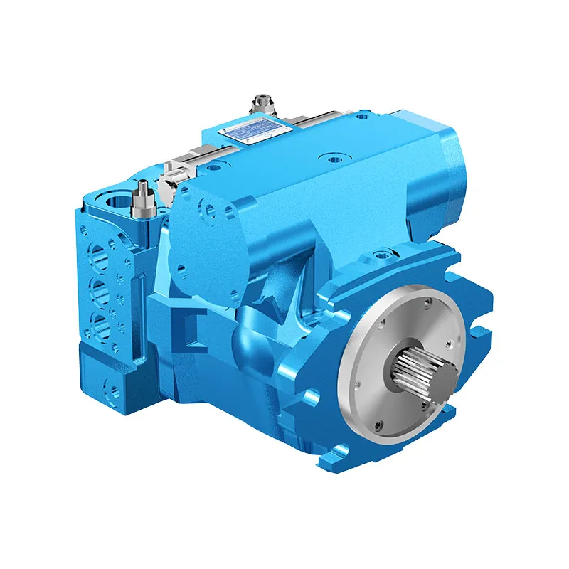
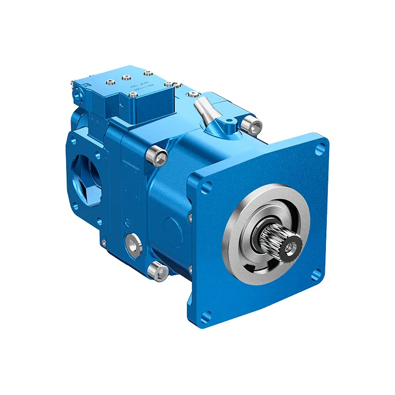
A4VG Closed Circuit Variable Piston Pump
The A4VG variable displacement pump is offered for closed-circuit hydraulic drives. The boost supply, high-pressure loop and control arrangement form one selection problem, especially where a drive reverses or sees an overrunning load.
- Integrated boost and pilot supply
- Reversible flow through neutral
- High-pressure relief functions
- Pressure cut-off configuration
PRANCE HYDRAULIC · PRODUCT SERIES
A4VG Closed Circuit Variable Piston Pump
Axial piston; variable swashplate · Closed circuit
The A4VG variable displacement pump is offered for closed-circuit hydraulic drives. The boost supply, high-pressure loop and control arrangement form one selection problem, especially where a drive reverses or sees an overrunning load.
Modèle
✓
Demander un devisVoir les données techniques et la fiche techniqueA4VGAxial piston; variable swashplate
Confirm the complete model and approved specification with Prance Hydraulic. Product-series references alone do not establish interchangeability.
Étude de configuration · Documentation technique · Sélection de produits
Détails du produit
- Integrated boost and pilot supply
- Reversible flow through neutral
- High-pressure relief functions
- Pressure cut-off configuration
CATÉGORIES : Pompe à piston, Pompe à cylindrée variable
A4VG Features & Application
Integrated boost and pilot supply
Account for pilot or replenishment demand and the relevant pressure limits. Include filtration and the return or drain route in the circuit review.
Reversible flow through neutral
Review combined drive torque and simultaneous demand, including any additional pump connected to the drive.
High-pressure relief functions
Keep continuous, intermittent and peak conditions separate. Use the row for the selected size and configuration.
Pressure cut-off configuration
Keep continuous, intermittent and peak conditions separate. Use the row for the selected size and configuration.
A4VG Specifications
| Series / model | A4VG |
|---|---|
| Product type | A4VG Closed Circuit Variable Piston Pump |
| Conception | Axial piston; variable swashplate |
| Circuit / selection | Closed circuit |
| Published nominal sizes | 28, 40, 56, 71, 90, 125 and 180 |
| Circuit | Closed circuit |
A4VG Selection & Configuration
The A4VG variable displacement pump is offered for closed-circuit hydraulic drives. The boost supply, high-pressure loop and control arrangement form one selection problem, especially where a drive reverses or sees an overrunning load.
Check pressure cut-off, high-pressure relief and boost-pressure settings separately. Provide the motor, flushing demand, maximum drive speed and control signal. Confirm the model series and through-drive requirements before comparing another A4VG or AA4VG unit.

Your Application.
The Right Configuration.
Hydraulic pumps · Hydraulic motors · Hydraulic valves
Send the MS nameplate, operating requirements and installation drawing for a configuration review before quoting.
- Model review — send the full model code or an existing nameplate photograph.
- Interface matching — confirm shaft, mounting flange, rotation and ports.
- Operating conditions — provide flow, pressure, speed, fluid and duty cycle.
- Documentation — request the relevant product data and drawings for your review.

A4VG Buying Guide
Use this sequence to prepare the A4VG configuration for review and quotation.
- Define required flow at the actual drive speed and continuous pressure.
- Identify peak pressure, duration and the work cycle.
- Confirm the selected displacement control and any auxiliary-drive requirement.
- Match rotation viewed from the shaft end, shaft, flange and ports.
- Review inlet conditions, drain routing and the installation envelope.
- Confirm fluid, viscosity, temperature, filtration and seals.
- Approve the complete model, control, drawing, quantity and delivery terms.

Selection, Documentation & Project Support

Selection Support
Learn more →Share your hydraulic circuit, operating point and installation requirements for a configuration discussion.
Flow · Pressure · Speed · Interfaces

Technical Resources
Learn more →Review product documentation, model codes and technical data before finalizing the specification.
Datasheets · Model codes · Drawings

cURL Too many subrequests by single Worker invocation. To configure this limit, refer to https://developers.cloudflare.com/workers/wrangler/configuration/#limits
Learn more →cURL Too many subrequests by single Worker invocation. To configure this limit, refer to https://developers.cloudflare.com/workers/wrangler/configuration/#limits.
cURL Too many subrequests by single Worker invocation. To configure this limit, refer to https://developers.cloudflare.com/workers/wrangler/configuration/#limits
Configuration, Quantity & Delivery
Confirm the complete MS code, approved drawing and operating limits. Availability, quantity, documentation and delivery date are confirmed in the quotation.
Discuss Your A4VG Application
Send the full model code, operating duty, installation details and quantity.
Request a A4VG QuotationA4VG Questions Before Ordering
What type of product is the A4VG?
A4VG Closed Circuit Variable Piston Pump. Design: Axial piston; variable swashplate. Closed circuit. Confirm the complete order code for the offered version.
Can a similar pump replace the A4VG?
cURL Too many subrequests by single Worker invocation. To configure this limit, refer to https://developers.cloudflare.com/workers/wrangler/configuration/#limits.
cURL Too many subrequests by single Worker invocation. To configure this limit, refer to https://developers.cloudflare.com/workers/wrangler/configuration/#limits
Define required flow at the actual drive speed and continuous pressure. Identify peak pressure, duration and the work cycle. Attach the nameplate, complete order code, installation drawing and required quantity.
A4VG Technical Data & Documents
View A4VG catalog data and operating conditions
cURL Too many subrequests by single Worker invocation. To configure this limit, refer to https://developers.cloudflare.com/workers/wrangler/configuration/#limits.
Données techniques
| Size Displacement.geometric.per revolution | NG | 28 | 40 | 56 | 71 | 90 | 125 | 180 | |||
| variable pump | VGiga | cm3 | 28 | 40 | 56 | 71 | 90 | 125 | 180 | ||
| boost pump (at p=20bar) | VgSp | cm3 | 6.1 | 8.6 | 11.6 | 19.6 | 19.6 | 28.3 | 39.8 | ||
| Vitesse de rotation1) | maximum at VGiga | nnom | tours par minute | 4250 | 4000 | 3600 | 3300 | 3050 | 2850 | 2500 | |
| limted,maximum2) | nmax1 | tours par minute | 4500 | 4200 | 3900 | 3600 | 3300 | 3250 | 2900 | ||
| intermittent,maximum3) | ncURL Too many subrequests by single Worker invocation. To configure this limit, refer to https://developers.cloudflare.com/workers/wrangler/configuration/#limits | tours par minute | 5000 | 5000 | 4500 | 4100 | 3800 | 3450 | 3000 | ||
| minimum | nmin | tours par minute | 500 | 500 | 500 | 500 | 500 | 500 | 500 | ||
| Couple4) | à VGiga et | Δp = 440 bar | T | Rien | 178 | 255 | 357 | 452 | 573 | 796 | 1146 |
| Δp = 100 bar | T | Rien | 45 | 64 | 89 | 113 | 143 | 199 | 286 | ||
| Rotary stiffness of drive shaft | S | c | kNm/rad | 31.4 | 69 | 80.8 | 98.8 | 158.1 | 218.3 | 244.5 | |
| T | c | kNm/rad | – | – | 95 | 120.9 | – | 252.1 | 318.4 | ||
| A | c | kNm/rad | – | 79.6 | 95.8 | 142.4 | 176.8 | 256.5 | – | ||
| Z | c | kNm/rad | 32.8 | 67.5 | 78.8 | 122.8 | 137 | 223.7 | 319.6 | ||
| U | c | kNm/rad | – | 50.8 | – | – | 107.6 | – | – | ||
| Moment d'inertie pour le groupe rotatif | JTW | Kgm2 | 0.0022 | 0.0038 | 0.0066 | 0.0097 | 0.0149 | 0.0232 | 0.0444 | ||
| Accélération angulaire maximale5) | α | rad/s2 | 38000 | 30000 | 24000 | 21000 | 18000 | 14000 | 11000 | ||
| Volume du boîtier | V | L | 0.9 | 1.1 | 1.5 | 1.3 | 1.5 | 2.1 | 3.1 | ||
| Weight (without through drive) approx. | m | kg | 29 | 31 | 38 | 50 | 60 | 80 | 101 | ||
Avis
▶Theoretical values, without efficiency and tolerances;values rounded ▶Operation above the maximum values or below the minimum values may result in a loss of function, a reduced service life or in the destruction of the axial piston unit.Determining the operation characteristics
Clé
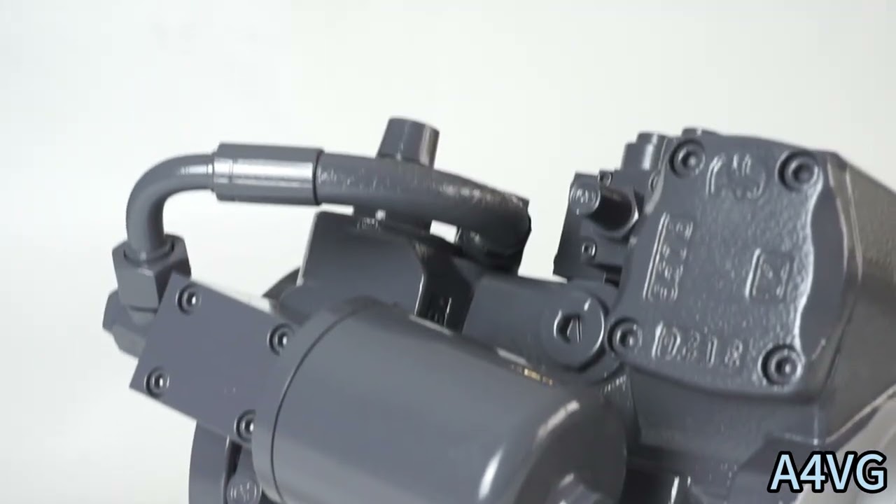
Vg Déplacement par révolution en [cm3] Δp Differential pressure [bar] n Rotational speed [rpm] ηv Volumetric efficiency ηhm Hydraulic-mechanical efficiency ηt Efficacité totale (ηt= ηv*ηhm) 1) The values are applicable: – for the optimum viscosity range from n =36 to 16mm2/s – for hydraulic fluid based on mineral oils (for HF hydraulic fluids,observe the technical data in 90225) 2)Valid at half corner power (e.g.at VGiga and p,/2) 3) Valid at Δp=70 to 150 bar or Δp < 300 bar and t<0.1s 4) Without boost pump 5) The data are valid for values between the minimum required and maximum permissible rotational speed.Valid for external excitation (e.g.diesel engine 2 to 8 times rotary frequency,cardan shaft twice the rotar frequency). The limit value is only valid for a single pump. The load capacity of the connection parts must be considered.Watch A4VG Product Video
Related Selection Resources
Request a A4VG Quotation
Tell us your required configuration, quantity and application.
Produits associés
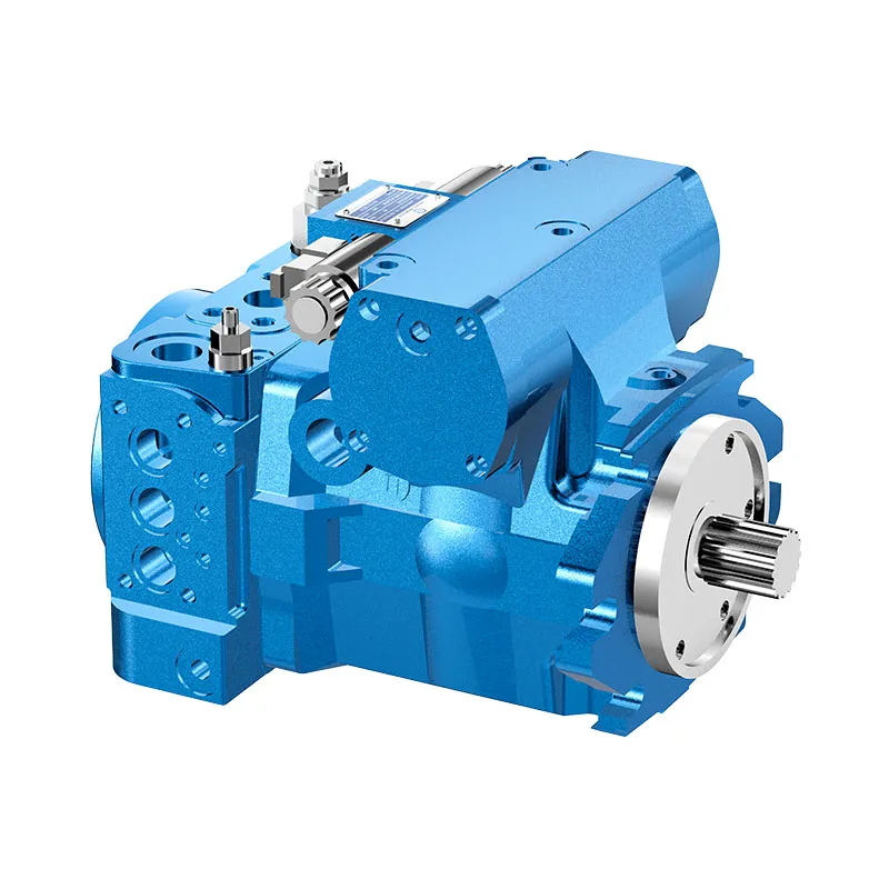
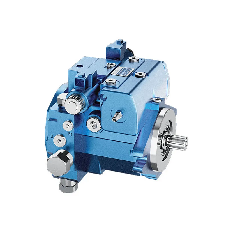
Compare related hydraulic pumps and confirm the complete configuration for your application.

Code source
| 01 | 02 | 03 | 04 | 05 | 06 | 07 | 08 | 09 | 10 | 11 | 12 | 13 | 14 | 15 | 16 | 17 | 18 | 19 | 20 | 21 | 22 | ||
| A4V | G | D | / | 32 | - | N |
Unité à pistons axiaux
| 01 | Conception à plateau oscillant, variable, pression nominale de 400 bars, pression maximale de 450 bars | A4V |
Mode de fonctionnement
| 02 | Pompe, circuit fermé | G |
Taille (NG)
| 03 | Cylindrée géométrique, voir " Données techniques " à la page 8 | 28 | 40 | 56 | 71 | 90 | 125 | 180 |
Dispositif de commande
| 28 | 40 | 56 | 71 | 90 | 125 | 180 | |||||
| 04 | Sans module de commande | ● | ● | ● | ● | ● | ● | ● | NV | ||
| Contrôle proportionnel, hydraulique | Lié à la pression de pilotage p = 6 à 18 bar | ● | ● | ● | ● | ● | ● | ● | HD3 | ||
| Servomécanisme mécanique | ● | ● | ● | ● | ● | ● | ● | Devoir | |||
| Commande proportionnelle, électrique | U=12V | ● | ● | ● | ● | ● | ● | ● | ÉP3 | ||
| U=24V | ● | ● | ● | ● | ● | ● | ● | EP4 | |||
| Régulation à deux points, électrique | U=12V | ● | ● | ● | ● | ● | ● | ● | EZ1 | ||
| U=24V | ● | ● | ● | ● | ● | ● | ● | EZ2 | |||
| Commande automatique, liée à la vitesse | U=12V | ● | ● | ● | ● | ● | ● | ● | DA1 | ||
| U=24V | ● | ● | ● | ● | ● | ● | ● | DA2 | |||
| commande hydraulique, à action directe | ● | ● | ● | ● | ● | ● | ● | DG | |||
| Commande électrique, à action directe,
deux détendeurs de pression |
U=12V | ● | ● | ● | ● | - | - | - | ET5 | ||
| U=24V | ● | ● | ● | ● | - | - | - | ET6 | |||
Coupure par pression
| 05 | Coupure par pression (standard) | D |
Contacteur de position neutre
| 06 | Sans interrupteur de position neutre (sans code) | ● | |
| Interrupteur de position neutre (pour commande matérielle uniquement) | ● | L |
Limiteur de course mécanique
| 07 | Sans limiteur de course mécanique (sans code) | ● | |
| Limiteur de course mécanique, réglable de l'extérieur | ● | M |
Orifice de pression de la chambre de manœuvre
| 06 | Sans actionner l'orifice de pression de chambre X3, X4 sans code | ● | |
| Port de pression de la chambre de manœuvre X3, X4 | ● | T |
vanne de régulation DA
| NV | HD | Devoir | DG | DA | EP | Facile | ||||
| 09 | Sans vanne de régulation DA | ● | ● | ● | ● | - | ● | ● | 1 | |
| soupape de commande DA, réglage fixe | - | ● | ● | ● | ● | ● | - | 2 | ||
| distributeur DA, réglable mécaniquement avec levier de position | sens d'actionnement, horaire | - | ● | ● | ● | ● | ● | - | 3R | |
| sens d'actionnement,
dans le sens inverse des aiguilles d'une montre |
- | ● | ● | ● | ● | ● | - | 3L | ||
| distributeur DA, réglage fixe, orifices pour dispositif de commande pilote | - | ● | ● | - | ● | ● | - | 7 | ||
| Distributeur DA, tarage fixe et vanne de coupure de frein (incheur) montés, commande au liquide de frein | à base d'huile minérale | - | - | - | - | ● | - | - | 8 | |
• = disponible ○ = sur demande - = non disponible  = programme préféré
Séries
| 10 | Série 3, indice 2 | 32 |
Sens de rotation
| 11 | Vu du côté de l'arbre | dans le sens des aiguilles d'une montre | R |
| dans le sens inverse des aiguilles d'une montre | L |
Matériau d'étanchéité
| 12 | caoutchouc nitrile (NBR), bague d'étanchéité d'arbre en FKM (fluoroélastomère) | N |
Arbre de transmission
| 28 | 40 | 56 | 71 | 90 | 125 | 180 | ||||
| 13 | Arbre cannelé
DIN 5480 |
pour pompe unique | ● | ● | ● | ● | ● | ● | ● | Z |
| pour pompe combinée - 1ère pompe | _1) | ● | ● | ● | ● | ● | _2) | A | ||
| Arbre cannelé
ANSI B92.1a |
pour pompe unique | ● | ● | ● | ● | ● | ● | ● | S | |
| pour pompe combinée - 1ère pompe | _2) | _2) | ● | ● | _2) | ● | ● | T | ||
| pour pompe combinée - 2e pompe | - | ● | - | - | ● | - | - | U |
Bride de fixation
| 28 | 40 | 56 | 71 | 90 | 125 | 180 | ||||
| 14 | SAE J744 | à deux trous | ● | ● | ● | - | - | - | - | C |
| à 4 trous | - | - | - | - | - | - | ● | D | ||
| 2+4 trous | - | - | - | ● | ● | ● | - | F |
Port en eau profonde
| 28 | 40 | 56 | 71 | 90 | 125 | 180 | ||||
| 15 | Port de travail SAE A et B, haut et bas | Orifice d'aspiration S inférieur | - | ● | ● | ● | ● | ● | ● | 02 |
| Port de travail SAE A et B, haut et bas | Orifice d'aspiration S haut | - | ● | ● | ○ | ○ | ○ | ○ | 03 | |
| Port de travail SAE A et B, même côté droit3) | Orifice d'aspiration S inférieur | ● | - | - | - | - | - | - | 10 | |
| SAE Working port A and B, same side left3) | Orifice d'aspiration S inférieur | - | - | - | ● | ○ | ● | - | ||
| Port de travail SAE A et B, même côté droit3) | Orifice d'aspiration S haut | - | - | - | ○ | ○ | ○ | - | 13 | |
| SAE Working port A and B, same side left3) | Orifice d'aspiration S haut | ● | - | ● | - | - | - | - |
Boost pump
| 16 | Without integrated boost pump | sans entraînement direct | N |
| with through drive | K | ||
| Integrated boost pump | with and without through drive | F |
Drive
| 28 | 40 | 56 | 71 | 90 | 125 | 180 | ||||
| 17 | Without through drive, versions N and F(no. 16) only | ● | ● | ● | ● | ● | ● | ● | 00 | |
| Flange SAE J7444) | Moyeu pour arbre cannelé | |||||||||
| 82-2(A) | 5/8 in 9T 16/32DP5) | ● | ● | ● | ● | ● | ● | ● | 01 | |
| 101-2(B) | 7/8 in 13T 16/32DP5) | ● | ● | ● | ● | ● | ● | ● | 02 | |
| 1 in 15T 16/32DP5) | ● | ● | ● | ● | ● | ● | ● | 04 | ||
| 127-2(C) | 1 in 15T 16/32DP5) | - | ● | - | - | - | - | - | 09 | |
| 1 1/4 in 14T 12/24DP5) | - | - | ● | ● | ● | ● | ● | 07 | ||
| 52-2/4(D) | W35 2X16X9g7) | - | - | - | - | ● | - | - | 73 | |
| 1 3/4 in 13T 8/16DP5) | - | - | - | - | - | ● | ● | 69 | ||
| 165-4(E) | 1 3/4 in 13T 8/16DP5) | - | - | - | - | - | - | ● | 72 | |
• = disponible ○ = sur demande - = non disponible
1)Standard for combination pump-1st pump:Shaft Z
2) Standard for combination pump -1st pump:Shaft S
3) Only possible without attachment filter
4)2=2-hole;4=4-hole
5) Hub for splined shaft to ANSI B92.1a
6) NG90 to 180 with additional 4-hole-flange (127-4)
7) Hub for splined shaft according to DIN 5480.
High-pressure relief valve
| Setting rabe Δp | 28 | 40 | 56 | 71 | 90 | 125 | 180 | ||||
| 18 | High-pressure relief valve,pilot operated | 100 to 420 bar | with bypass | - | - | - | ● | ● | ● | ● | 1 |
| High-pressure relief valve,direch operated, fixed setting | 250 to 420 bar | without bypass | ● | ● | ● | - | - | - | - | 3 | |
| with bypass | ● | ● | ● | - | - | - | - | 5 | |||
| 100 to 250 bar | without bypass | ● | ● | ● | - | - | - | - | 4 | ||
| with bypass | ● | ● | ● | - | - | - | - | 6 | |||
Filtration boost circuit/external boost pressure supply
| 28 | 40 | 56 | 71 | 90 | 125 | 180 | |||
| 19 | Filtration in the boost pump suction line | ● | ● | ● | ● | ● | ● | ● | S |
| Filtration in the boost pump pressure line
Porst for external boost circuit filtration (Fe et Fa) |
● | ● | ● | ● | ● | ● | ● | D | |
| Attachment filter with cold start valve | - | ● | ● | ● | ● | ● | ● | F | |
| Attachment filter with cold start valve and visual contamation indicator | - | ● | ● | ● | ● | ● | ● | P | |
| Attachment filter with cold start valve and electric contamation indicator | - | ● | ● | ● | ● | ● | ● | B | |
| External boost pressure supply (version without integrated boost pump-N00, K...) | ● | ● | ● | ● | ● | ● | ● | E |
Capteur d'angle de rotation
| 28 to 180 | |||
| 20 | Sans capteur d'angle de rotation (sans code) | ● | |
| Capteur électrique d'angle de rotation8) | ● | R |
Connecteur pour solénoïdes9)
| 28 to 180 | ||||
| 21 | Without connector (without code),only for purely hydraulic control | ● | ||
| cURL Too many subrequests by single Worker invocation. To configure this limit, refer to https://developers.cloudflare.com/workers/wrangler/configuration/#limits | cURL Too many subrequests by single Worker invocation. To configure this limit, refer to https://developers.cloudflare.com/workers/wrangler/configuration/#limits | ● | P | |
| cURL Too many subrequests by single Worker invocation. To configure this limit, refer to https://developers.cloudflare.com/workers/wrangler/configuration/#limits | ● | Q | ||
Standard/special version
| 22 | Version standard | sans code | |
| combined with attachment part or attachment pump | -K | ||
| Version spéciale | -S | ||
| combined with attachment part or attachment pump | cURL Too many subrequests by single Worker invocation. To configure this limit, refer to https://developers.cloudflare.com/workers/wrangler/configuration/#limits |
cURL Too many subrequests by single Worker invocation. To configure this limit, refer to https://developers.cloudflare.com/workers/wrangler/configuration/#limits = programme préféré
Avis
cURL Too many subrequests by single Worker invocation. To configure this limit, refer to https://developers.cloudflare.com/workers/wrangler/configuration/#limits
cURL Too many subrequests by single Worker invocation. To configure this limit, refer to https://developers.cloudflare.com/workers/wrangler/configuration/#limits.
8)cURL Too many subrequests by single Worker invocation. To configure this limit, refer to https://developers.cloudflare.com/workers/wrangler/configuration/#limits
9) Les connecteurs pour d'autres composants électriques peuvent différer.
Données techniques
| Taille
cURL Too many subrequests by single Worker invocation. To configure this limit, refer to https://developers.cloudflare.com/workers/wrangler/configuration/#limits |
NG | 28 | 40 | 56 | 71 | 90 | 125 | 180 | |||
| variable pump | VGiga | cm3 | 28 | 40 | 56 | 71 | 90 | 125 | 180 | ||
| boost pump (at p=20bar) | VgSp | cm3 | 6.1 | 8.6 | 11.6 | 19.6 | 19.6 | 28.3 | 39.8 | ||
| Vitesse de rotation1) | maximum at VGiga | nnom | tours par minute | 4250 | 4000 | 3600 | 3300 | 3050 | 2850 | 2500 | |
| limted,maximum2) | nmax1 | tours par minute | 4500 | 4200 | 3900 | 3600 | 3300 | 3250 | 2900 | ||
| intermittent,maximum3) | ncURL Too many subrequests by single Worker invocation. To configure this limit, refer to https://developers.cloudflare.com/workers/wrangler/configuration/#limits | tours par minute | 5000 | 5000 | 4500 | 4100 | 3800 | 3450 | 3000 | ||
| minimum | nmin | tours par minute | 500 | 500 | 500 | 500 | 500 | 500 | 500 | ||
| Flux | à nnom et VGiga | qv | L/min | 119 | 160 | 202 | 234 | 275 | 356 | 450 | |
| Puissance4) | à nnom,VGiga and Δp = 400 bar | P | kW | 79 | 107 | 134 | 156 | 183 | 238 | 300 | |
| Couple4) | à VGiga et | Δp = 440 bar | T | Rien | 178 | 255 | 357 | 452 | 573 | 796 | 1146 |
| Δp = 100 bar | T | Rien | 45 | 64 | 89 | 113 | 143 | 199 | 286 | ||
| Rotary stiffness of drive shaft | S | c | kNm/rad | 31.4 | 69 | 80.8 | 98.8 | 158.1 | 218.3 | 244.5 | |
| T | c | kNm/rad | - | - | 95 | 120.9 | - | 252.1 | 318.4 | ||
| A | c | kNm/rad | - | 79.6 | 95.8 | 142.4 | 176.8 | 256.5 | - | ||
| Z | c | kNm/rad | 32.8 | 67.5 | 78.8 | 122.8 | 137 | 223.7 | 319.6 | ||
| U | c | kNm/rad | - | 50.8 | - | - | 107.6 | - | - | ||
| Moment d'inertie pour le groupe rotatif | JTW | Kgm2 | 0.0022 | 0.0038 | 0.0066 | 0.0097 | 0.0149 | 0.0232 | 0.0444 | ||
| Accélération angulaire maximale5) | α | rad/s2 | 38000 | 30000 | 24000 | 21000 | 18000 | 14000 | 11000 | ||
| Volume du boîtier | V | L | 0.9 | 1.1 | 1.5 | 1.3 | 1.5 | 2.1 | 3.1 | ||
| Weight (without through drive) approx. | m | kg | 29 | 31 | 38 | 50 | 60 | 80 | 101 | ||
Avis
▶Valeurs théoriques, sans efficacité ni tolérances ; valeurs arrondies
▶Operation above the maximum values or below the minimum values may result in a loss of function, a reduced service life or in the destruction of the axial piston unit.
Determining the operation characteristics
| Flux | qv=(Vg ∙ n ∙ ηv) / 1000 | L/min |
| Couple | T=(Vg ∙ Δp) / 20 ∙ π ∙ ηhm | Rien |
| Puissance | P=(2π ∙ T ∙ n)/60000=(qv ∙ Δp)/600 ∙ ηt | kW |
Clé
Vg Déplacement par révolution en [cm3]
Δp Pression différentielle [bar]
n Rotational speed [rpm]
ηv Efficacité volumétrique
ηhm Efficacité hydraulico-mécanique
ηt Efficacité totale (ηt= ηv*ηhm)
1) Les valeurs sont applicables :
- for the optimum viscosity range from n =36 to 16mm2/s
- for hydraulic fluid based on mineral oils (for HF hydraulic fluids,observe the technical data in 90225)
2)Valid at half corner power (e.g.at VGiga and p,/2)
3) Valid at Δp=70 to 150 bar or Δp < 300 bar and t<0.1s
4) Without boost pump
5) The data are valid for values between the minimum required and maximum permissible rotational speed.Valid for external excitation (e.g.diesel engine 2 to 8 times rotary frequency,cardan shaft twice the rotar frequency).
The limit value is only valid for a single pump.
The load capacity of the connection parts must be considered.
