Wenzhou Prance Hydraulic Equipment Co., Ltd.


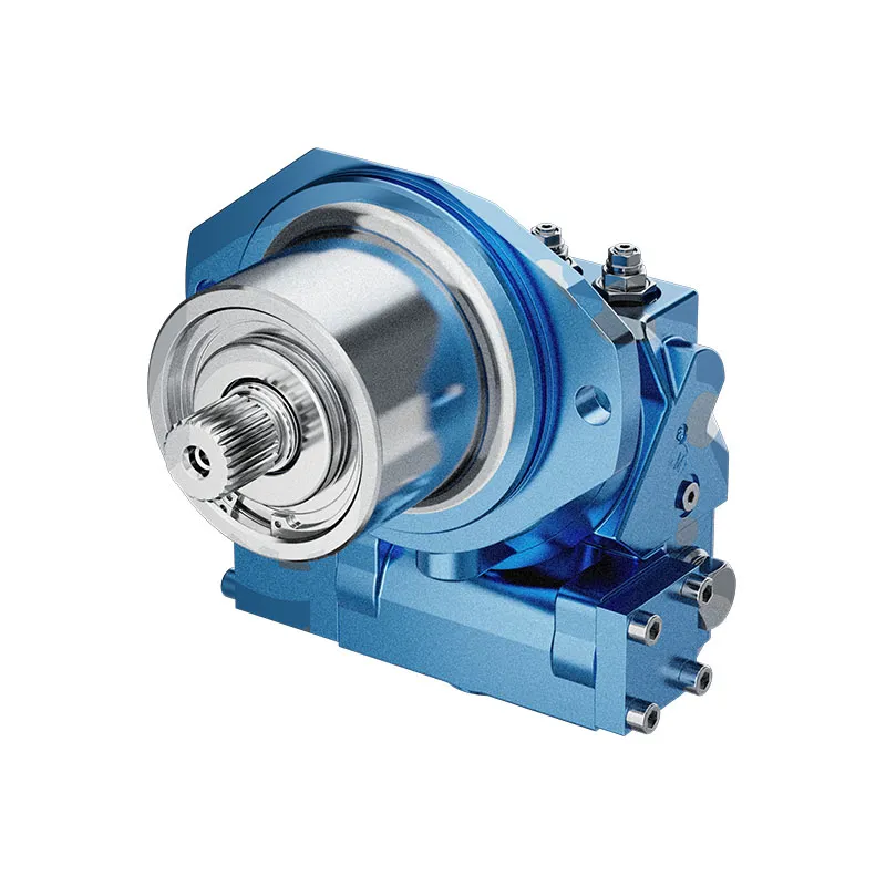
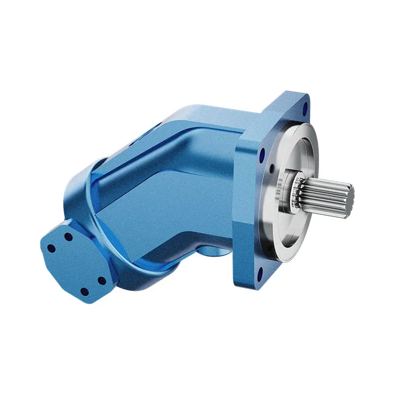
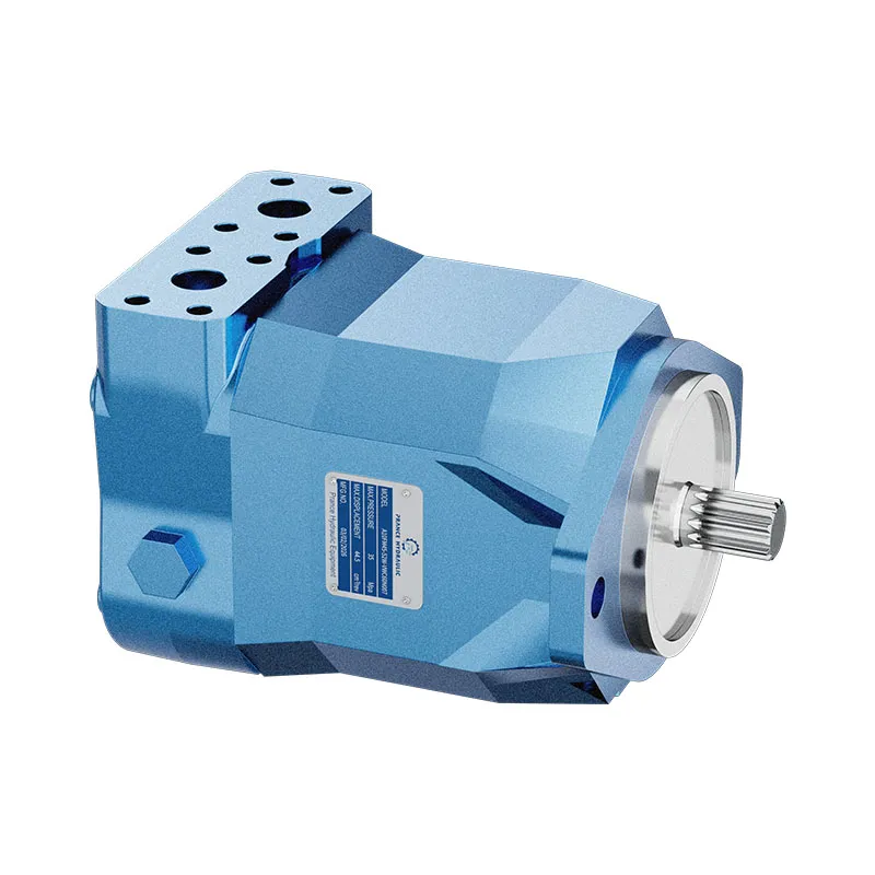
A2FE Fixed Displacement Bent Axis Motor
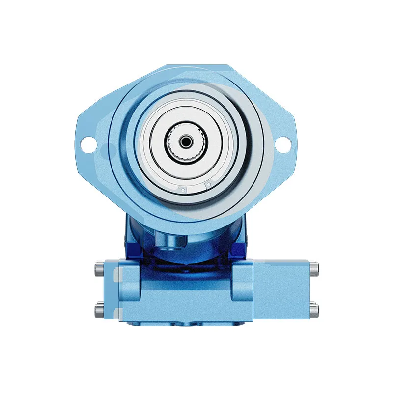
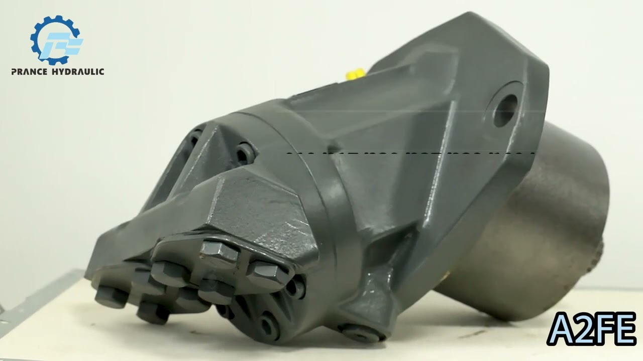
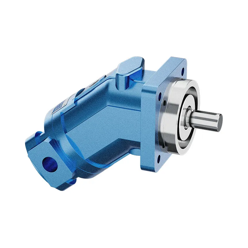
The A2FE is a fixed displacement bent-axis hydraulic motor. Its installation arrangement must be reviewed from the A2FE drawing; a related A2FM description does not establish that its housing and mounting interface are interchangeable.
- Fixed displacement axial piston motor
- Bent-axis construction
- Installation interface must match the A2FE drawing
- Output depends on flow and pressure difference
PRANCE HYDRAULIC · PRODUCT SERIES
A2FE Fixed Displacement Bent Axis Motor
Axial piston; bent axis, fixed displacement · Open and closed circuits, subject to configuration
The A2FE is a fixed displacement bent-axis hydraulic motor. Its installation arrangement must be reviewed from the A2FE drawing; a related A2FM description does not establish that its housing and mounting interface are interchangeable.
Model
✓
Request a QuotationTechnische Daten & Datenblatt anzeigenA2FEAxial piston; bent axis, fixed displacement
Confirm the complete model and approved specification with Prance Hydraulic. Product-series references alone do not establish interchangeability.
Configuration review · Technical documentation · Product selection
Produktdetails
- Fixed displacement axial piston motor
- Bent-axis construction
- Installation interface must match the A2FE drawing
- Output depends on flow and pressure difference
CATEGORIES: Konstantmotor, Kolbenmotor
A2FE Features & Application
Fixed displacement axial piston motor
For a fixed displacement, flow and speed remain linked by the selected displacement. Check the actual operating point and efficiency.
Bent-axis construction
Specify the full MS order code, installation drawing and operating duty so the quotation can identify the proposed configuration.
Installation interface must match the A2FE drawing
Check pilot diameter, bolt pattern, shaft engagement or port pattern against the approved installation drawing.
Output depends on flow and pressure difference
Keep continuous, intermittent and peak conditions separate. Use the row for the selected size and configuration.
A2FE Specifications
| Series / model | A2FE |
|---|---|
| Product type | A2FE Fixed Displacement Bent Axis Motor |
| Design | Axial piston; bent axis, fixed displacement |
| Circuit / selection | Open and closed circuits, subject to configuration |
| Hubregelung | Fixed |
| Technical document | A2FE series document; check the complete configuration |
A2FE Selection & Configuration
The A2FE is a fixed displacement bent-axis hydraulic motor. Its installation arrangement must be reviewed from the A2FE drawing; a related A2FM description does not establish that its housing and mounting interface are interchangeable.
Start a replacement enquiry with the A2FE nameplate and a drawing of the gearbox or mounting location. Check shaft engagement, housing clearance, port access and the drain route. Apply pressure and speed limits to the exact size and series rather than the family as a whole.

cURL Too many subrequests by single Worker invocation. To configure this limit, refer to https://developers.cloudflare.com/workers/wrangler/configuration/#limits.
cURL Too many subrequests by single Worker invocation. To configure this limit, refer to https://developers.cloudflare.com/workers/wrangler/configuration/#limits.
Hydraulic pumps · Hydraulic motors · Hydraulic valves
Send the MS nameplate, operating requirements and installation drawing for a configuration review before quoting.
- Model review — send the full model code or an existing nameplate photograph.
- Interface matching — confirm shaft, mounting flange, rotation and ports.
- Operating conditions — provide flow, pressure, speed, fluid and duty cycle.
- Documentation — request the relevant product data and drawings for your review.

A2FE Buying Guide
Use this sequence to prepare the A2FE configuration for review and quotation.
- Define starting and continuous torque, speed range and duty cycle.
- Specify available flow, work-port pressure difference and return pressure.
- Confirm the displacement setting and required behavior during starting and stopping.
- Check shaft, mounting pilot, flange, port orientation and external loads.
- Review case drainage, replenishment and any displacement control.
- Specify fluid conditions and any independent braking requirement.
- Approve the complete model, operating envelope, drawing and quantity.
Selection, Documentation & Project Support

Selection Support
Learn more →Share your hydraulic circuit, operating point and installation requirements for a configuration discussion.
Flow · Pressure · Speed · Interfaces

Technical Resources
Learn more →Review product documentation, model codes and technical data before finalizing the specification.
Datasheets · Model codes · Drawings

Project Inquiries
Learn more →Send your required model, quantity, application and project requirements to discuss your inquiry.
Product inquiries · Configuration review
Configuration, Quantity & Delivery
Confirm the complete MS code, approved drawing and operating limits. Availability, quantity, documentation and delivery date are confirmed in the quotation.
Discuss Your A2FE Application
Send the full model code, operating duty, installation details and quantity.
Request a A2FE QuotationA2FE Questions Before Ordering
What type of product is the A2FE?
AA2FM Fixed Displacement Bent Axis Motor. Design: Axial piston; bent axis, fixed displacement. Open and closed circuits, subject to configuration. Confirm the complete order code for the offered version.
Can a similar motor replace the A2FE?
cURL Too many subrequests by single Worker invocation. To configure this limit, refer to https://developers.cloudflare.com/workers/wrangler/configuration/#limits.
cURL Too many subrequests by single Worker invocation. To configure this limit, refer to https://developers.cloudflare.com/workers/wrangler/configuration/#limits
cURL Too many subrequests by single Worker invocation. To configure this limit, refer to https://developers.cloudflare.com/workers/wrangler/configuration/#limits.
A2FE Technical Data & Documents
View A2FE catalog data and operating conditions
cURL Too many subrequests by single Worker invocation. To configure this limit, refer to https://developers.cloudflare.com/workers/wrangler/configuration/#limits.
Technische Daten
Pressure at port A or B Nominal pressure——–Pn = 35MPa Peak pressure———PMax = 40MPa The sum of the pressure at port A or B must not exceed 710MPa (Individual pressure on either.side max, 40MPa) Maximun pernissible case pressure Pca———–0.2MPa tmin.———— -25℃ tMax———— +80℃Viskositätsbereich
Vmin. (for short periods)——— 10mm2/s VMax (for short periods)——— 1000mm2/s Optimun Operating viscosity Vopt——— 16-36mm2/s Fluid Recommendations| Betriebstemperaturbereich | DIN51519 oder ISO(VG) Viskositätsklassen-Empfehlungen nach DIN51519ISO(VG) |
| 30–40 °C | VG22 22mm2/s bei 40 °C |
| 40-50℃ | VG35 32 mm2/s bei 40 °C |
| 50–60 °C | VG46 46mm2/s bei 40 °C |
| 60-70℃ | VG68 68mm2/s bei 40 °C |
| 70-80 °C | VG100 100 mm2/s bei 40 °C |
Filtration von FlUID
Empfohlene Filtration: 10 µm, eine gröbere Filtration von 25–40 µm ist möglich, aber mit einer Filtration von 10 µm wird eine längere Lebensdauer erreicht (Verschleißminderung).Geschwindigkeitsbereich
Keine Begrenzung der Mindestdrehzahl nmin., wenn eine hohe Gleichförmigkeit der Rotation erforderlich ist, nmin. sollte nicht unter 50 U/min liegen. Siehe Tabelle für die maximale Drehzahl nMax.Einbaulage
Optional. Das Gehäuse muss immer mit Öl gefüllt sein.Berechnung der Größe
| Motor | ||
| Fluss | Q=(Vg∙n)/(1000∙ηv) | (l/min) |
| Drehmoment | M=(1,59Vg∙Δp∙ηmöglicherweise) | (Nm) |
| Macht | P=Mn/9549=(Q∙Δp∙ηt)/60 | (KW) |
| Geschwindigkeit | n=(1000∙Q∙ηv)/Vg | (U/min) |
| Vg:geom.Verdrängung(ml/U) | ||
| Δp: Druckdifferenz (MPa) | ||
| Geschwindigkeit | ||
| ηvVolumenausnutzungsgrad | ||
| nMPmechanischer und hydraulischer Wirkungsgrad | ||
| ηtGesamteffizienz | ||
| [ηtηy∙ηmh] | ||
| Technische Daten (theoretische Werte, ohne Berücksichtigung von η)v∙ ηmh ∙Werte gerundet) | ||
| Größe | 55 | 80 | 107 | 125 | 160 | ||
| Verschiebung | Vg | ml/r | 54.8 | 80 | 107 | 126.3 | 160 |
| Höchstgeschwindigkeit | nMax | U/min | 3750 | 3350 | 3000 | 3000 | 2650 |
| Maximaler Durchfluss | QMax | l/min | 206 | 268 | 321 | 379 | 424 |
| Drehmomentkonstanten | MK | Nm/MPa | 8.71 | 12.74 | 16.97 | 20.1 | 25.40 |
| Max.Torque Δp=35MPa | M | Machs gut | 305 | 446 | 594 | 703.5 | 889 |
| Max. Power Δp=35MPa | P | KW | 120 | 156 | 187 | 221 | 247 |
| Moment of inertia about drive shaft | J | Kgm2 | 0.0052 | 0.0109 | 0.0167 | 0.0322 | 0.0532 |
| Gewicht (ca.) | Kg |
Watch A2FE Product Video
Related Selection Resources
Request a A2FE Quotation
Tell us your required configuration, quantity and application.
Ähnliche Produkte
Compare related hydraulic motors and confirm the complete configuration for your application.

Technische Daten
Druck an Anschluss A oder B
Nenndruck--------Pn = 35 MPa
Spitzendruck---------PMax = 40 MPa
Die Summe des Drucks an Anschluss A oder B darf 710 MPa nicht überschreiten.
(Einzeldruck auf jeder Seite max. 40 MPa)
Zulässiger Gehäusedruck
Pca-----------0,2 MPa
tmin.-25 ℃
tMax------------ +80℃
Viskositätsbereich
Vmin. (für kurze Zeit)--------- 10mm2/s
VMax (für kurze Zeit)--------- 1000mm2/s
Optimaler Betrieb
Viskosität
Vopt--------- 16-36 mm2/s
Flüssigkeitsempfehlungen
| Betriebstemperaturbereich | DIN51519 oder ISO(VG) Viskositätsklassen-Empfehlungen nach DIN51519ISO(VG) |
| 30–40 °C | VG22 22mm2/s bei 40 °C |
| 40-50℃ | VG35 32 mm2/s bei 40 °C |
| 50–60 °C | VG46 46mm2/s bei 40 °C |
| 60-70℃ | VG68 68mm2/s bei 40 °C |
| 70-80 °C | VG100 100 mm2/s bei 40 °C |
Filtration von FlUID
Empfohlene Filtration: 10 µm, eine gröbere Filtration von 25–40 µm ist möglich, aber mit einer Filtration von 10 µm wird eine längere Lebensdauer erreicht (Verschleißminderung).
Geschwindigkeitsbereich
Keine Begrenzung der Mindestdrehzahl nmin., wenn eine hohe Gleichförmigkeit der Rotation erforderlich ist, nmin. sollte nicht unter 50 U/min liegen. Siehe Tabelle für die maximale Drehzahl nMax.
Einbaulage
Optional. Das Gehäuse muss immer mit Öl gefüllt sein.
Berechnung der Größe
| Motor | ||
| Fluss | Q=(Vg∙n)/(1000∙ηv) | (l/min) |
| Drehmoment | M=(1,59Vg∙Δp∙ηmöglicherweise) | (Nm) |
| Macht | P=Mn/9549=(Q∙Δp∙ηt)/60 | (KW) |
| Geschwindigkeit | n=(1000∙Q∙ηv)/Vg | (U/min) |
| Vg:geom.Verdrängung(ml/U) | ||
| Δp: Druckdifferenz (MPa) | ||
| Geschwindigkeit | ||
| ηvVolumenausnutzungsgrad | ||
| nMPmechanischer und hydraulischer Wirkungsgrad | ||
| ηtGesamteffizienz | ||
| [ηtηy∙ηmh] | ||
| Technische Daten (theoretische Werte, ohne Berücksichtigung von η)v∙ ηmh ∙Werte gerundet) |
||
| Größe | 55 | 80 | 107 | 125 | 160 | ||
| Verschiebung | Vg | ml/r | 54.8 | 80 | 107 | 126.3 | 160 |
| Höchstgeschwindigkeit | nMax | U/min | 3750 | 3350 | 3000 | 3000 | 2650 |
| Maximaler Durchfluss | QMax | l/min | 206 | 268 | 321 | 379 | 424 |
| Drehmomentkonstanten | MK | Nm/MPa | 8.71 | 12.74 | 16.97 | 20.1 | 25.40 |
| Max. Drehmoment Δp=35MPa |
M | Machs gut | 305 | 446 | 594 | 703.5 | 889 |
| Max. Leistung Δp=35MPa |
P | KW | 120 | 156 | 187 | 221 | 247 |
| Trägheitsmoment Über die Antriebswelle |
J | Kgm2 | 0.0052 | 0.0109 | 0.0167 | 0.0322 | 0.0532 |
| Gewicht (ca.) | Kg |
