Wenzhou Prance Hydraulic Equipment Co., Ltd.

cURL Too many subrequests by single Worker invocation. To configure this limit, refer to https://developers.cloudflare.com/workers/wrangler/configuration/#limits
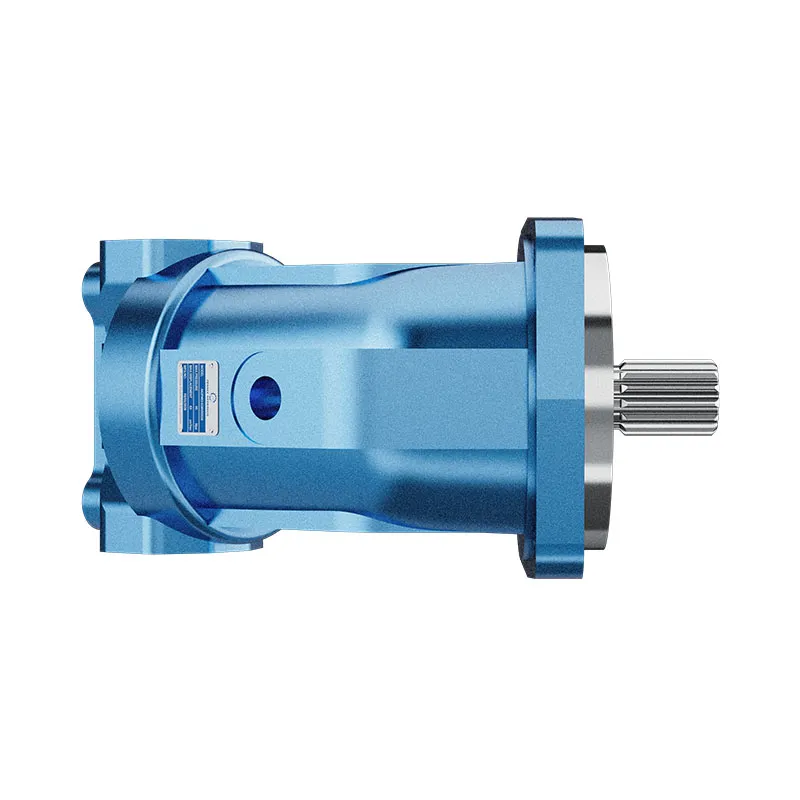
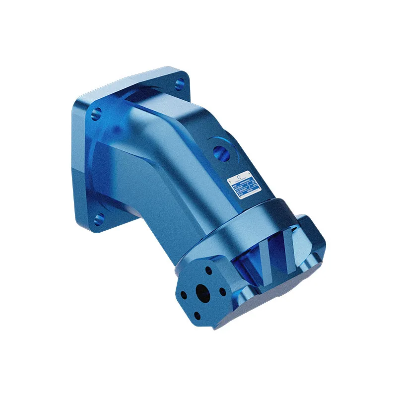
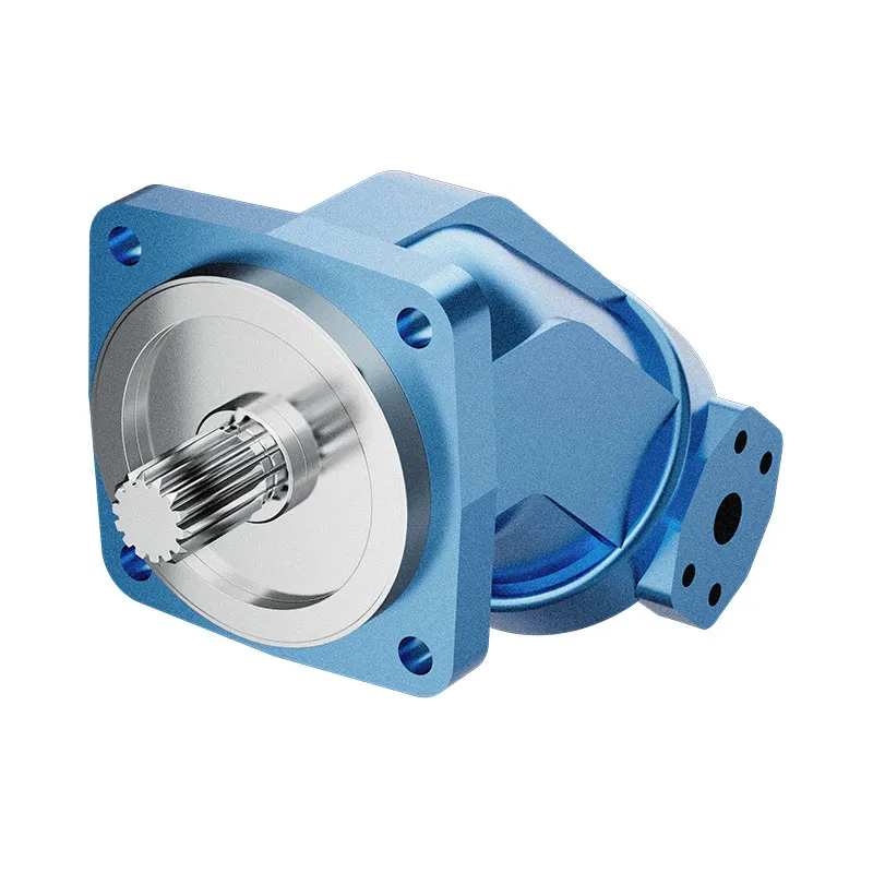
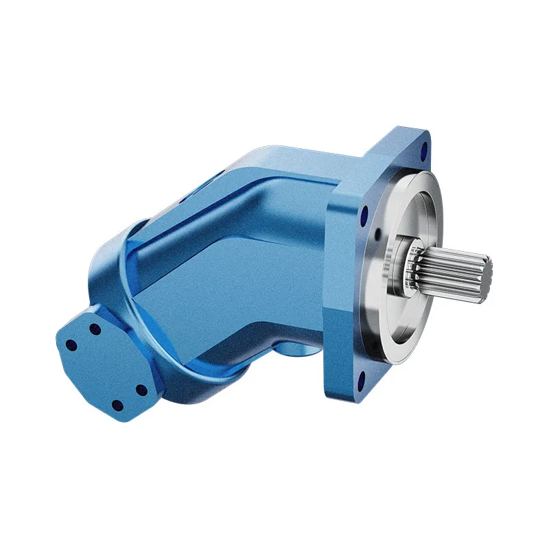
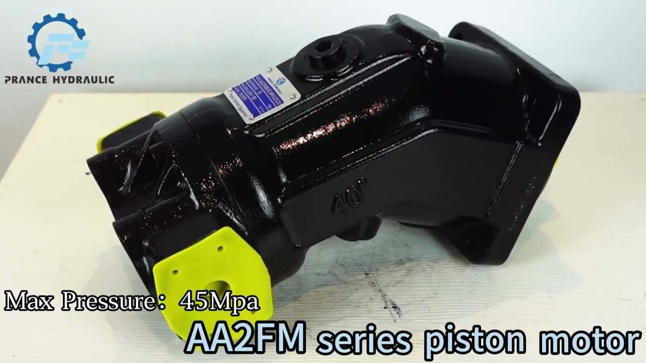
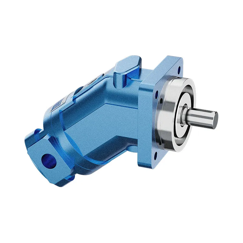
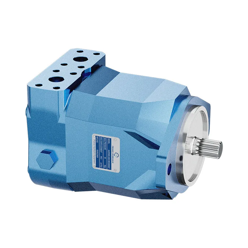
The AA2FM fixed displacement bent-axis motor is offered for mobile and industrial hydraulic drives. A fixed displacement means speed is primarily determined by inlet flow, while useful torque depends on pressure difference and mechanical efficiency.
- Fixed displacement motor
- Bent-axis axial piston construction
- Mobile and industrial hydraulic drives
- Fluid and case-pressure restrictions depend on configuration
PRANCE HYDRAULIC · PRODUCT SERIES
cURL Too many subrequests by single Worker invocation. To configure this limit, refer to https://developers.cloudflare.com/workers/wrangler/configuration/#limits
Axial piston; bent axis, fixed displacement · Open and closed circuits, subject to configuration
The AA2FM fixed displacement bent-axis motor is offered for mobile and industrial hydraulic drives. A fixed displacement means speed is primarily determined by inlet flow, while useful torque depends on pressure difference and mechanical efficiency.
Model
✓
Request a QuotationTechnische Daten & Datenblatt anzeigenAA2FMAxial piston; bent axis, fixed displacement
Confirm the complete model and approved specification with Prance Hydraulic. Product-series references alone do not establish interchangeability.
Configuration review · Technical documentation · Product selection
Produktdetails
- Fixed displacement motor
- Bent-axis axial piston construction
- Mobile and industrial hydraulic drives
- Fluid and case-pressure restrictions depend on configuration
CATEGORIES: Konstantmotor, Kolbenmotor
AA2FM Features & Application
Fixed displacement motor
For a fixed displacement, flow and speed remain linked by the selected displacement. Check the actual operating point and efficiency.
Bent-axis axial piston construction
Specify the full MS order code, installation drawing and operating duty so the quotation can identify the proposed configuration.
Mobile and industrial hydraulic drives
Check the required shaft torque and speed at the same operating point. Include starting duty, return pressure and external shaft loads.
Fluid and case-pressure restrictions depend on configuration
Confirm the actual fluid and temperature range. Seal and fluid compatibility must be checked for the supplied version.
AA2FM Specifications
| Series / model | AA2FM |
|---|---|
| Product type | cURL Too many subrequests by single Worker invocation. To configure this limit, refer to https://developers.cloudflare.com/workers/wrangler/configuration/#limits |
| Design | Axial piston; bent axis, fixed displacement |
| Circuit / selection | Open and closed circuits, subject to configuration |
| Hubregelung | Fixed |
| Fluid selection | Confirm fluid, seals and temperature restrictions for the selected size |
AA2FM Selection & Configuration
The AA2FM fixed displacement bent-axis motor is offered for mobile and industrial hydraulic drives. A fixed displacement means speed is primarily determined by inlet flow, while useful torque depends on pressure difference and mechanical efficiency.
AA2FM technical information includes fluid, temperature and case-pressure restrictions with size-dependent conditions. Keep the actual AA2FM order code and interface standard in the enquiry; do not substitute an A2FM connection drawing solely because displacement is similar.
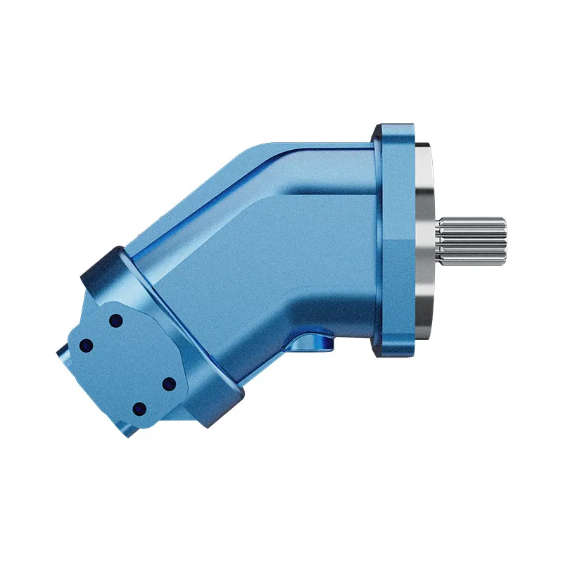
cURL Too many subrequests by single Worker invocation. To configure this limit, refer to https://developers.cloudflare.com/workers/wrangler/configuration/#limits.
cURL Too many subrequests by single Worker invocation. To configure this limit, refer to https://developers.cloudflare.com/workers/wrangler/configuration/#limits.
Hydraulic pumps · Hydraulic motors · Hydraulic valves
Send the MS nameplate, operating requirements and installation drawing for a configuration review before quoting.
- Model review — send the full model code or an existing nameplate photograph.
- Interface matching — confirm shaft, mounting flange, rotation and ports.
- Operating conditions — provide flow, pressure, speed, fluid and duty cycle.
- Documentation — request the relevant product data and drawings for your review.

AA2FM Buying Guide
Use this sequence to prepare the AA2FM configuration for review and quotation.
- Define starting and continuous torque, speed range and duty cycle.
- Specify available flow, work-port pressure difference and return pressure.
- Confirm the displacement setting and required behavior during starting and stopping.
- Check shaft, mounting pilot, flange, port orientation and external loads.
- Review case drainage, replenishment and any displacement control.
- Specify fluid conditions and any independent braking requirement.
- Approve the complete model, operating envelope, drawing and quantity.

Selection, Documentation & Project Support

Selection Support
Learn more →Share your hydraulic circuit, operating point and installation requirements for a configuration discussion.
Flow · Pressure · Speed · Interfaces

Technical Resources
Learn more →Review product documentation, model codes and technical data before finalizing the specification.
Datasheets · Model codes · Drawings

Project Inquiries
Learn more →Send your required model, quantity, application and project requirements to discuss your inquiry.
Product inquiries · Configuration review
Configuration, Quantity & Delivery
Confirm the complete MS code, approved drawing and operating limits. Availability, quantity, documentation and delivery date are confirmed in the quotation.
Discuss Your AA2FM Application
Send the full model code, operating duty, installation details and quantity.
Request a AA2FM QuotationAA2FM Questions Before Ordering
What type of product is the AA2FM?
AA2FM Fixed Displacement Bent Axis Motor. Design: Axial piston; bent axis, fixed displacement. Open and closed circuits, subject to configuration. Confirm the complete order code for the offered version.
Can a similar motor replace the AA2FM?
cURL Too many subrequests by single Worker invocation. To configure this limit, refer to https://developers.cloudflare.com/workers/wrangler/configuration/#limits.
cURL Too many subrequests by single Worker invocation. To configure this limit, refer to https://developers.cloudflare.com/workers/wrangler/configuration/#limits
cURL Too many subrequests by single Worker invocation. To configure this limit, refer to https://developers.cloudflare.com/workers/wrangler/configuration/#limits.
AA2FM Technical Data & Documents
View AA2FM catalog data and operating conditions
cURL Too many subrequests by single Worker invocation. To configure this limit, refer to https://developers.cloudflare.com/workers/wrangler/configuration/#limits.
Technische Daten
Hydraulikflüssigkeit
Before starting project planning, please refer to our data sheets RE 90220 (mineral oil), RE 90221 (environmentally acceptable hydraulic fluids), RE 90222 (HFD hydraulic fluids)and RE 90223 (HFA, HFB, HFC hydraulic fluids) for detailed information regarding the choice of hydraulic fluid and application conditions. The fixed motor AA2FM is not suitable for operation with HFA hydraulic fluid. If HFB, HFC or HFD or environmentally acceptable hydraulic fluids are used, the limitations regarding technical data or other seals must be observed.Auswahldiagramm
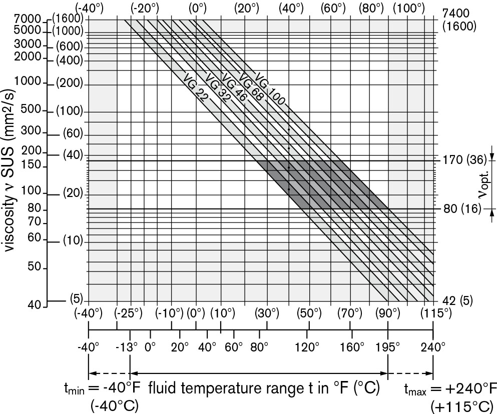
Viskosität und Temperatur von Hydraulikflüssigkeit
| Viscosity [SUS (mm2/s)] | Temperatur | Kommentar | |
| Transport and storage at ambient temperature | Tmin. ≥ -58 ℉ (-50 ℃) | factory preservation: up to 12 months with standard, up to 24 months with long-term | |
| Tentscheiden = +41 ℉ to +68℉ (+5℃ to + 20℃) | |||
| Kaltstart1) | VMax=7400(1600) | TSt.≥ -40℉ (-40℃) | t ≤ 3 min, ohne Last (p ≤ 725 psi (50 bar)), |
| n ≤ 1000 U/min (für Baugrößen 10 bis 180), | |||
| n ≤ 0,25 · nnom (für Größen 250) | |||
| Zulässiger Temperaturunterschied | ΔT ≤ 45 ℉ (25 ℃) | zwischen Axialkolbeneinheit und Hydraulikflüssigkeit | |
| Aufwärmphase | ν<7400 to 1850 (1600 to 400) | T= -40℉ to -13℉ (-40℃ to -25℃) | bei p ≤ 0,7·Pnom, n ≤ 0,5·nnom und t ≤ 15 min |
| Betriebsphase | |||
| Temperaturdifferenz | ΔT = ca. 22 ℉ (12 ℃) | zwischen der Hydraulikflüssigkeit im Lager und am Anschluss T. | |
| Höchsttemperatur | +240℉ (115℃) | im Lager | |
| +217 ℉ (103 ℃) | am Anschluss T gemessen | ||
| Dauerbetrieb | v=1850 bis 47 | T = -13 ℉ bis +195 ℉ | gemessen an Anschluss T, |
| (400 bis 10) | (-25℃ bis +90℃) | keine Einschränkung innerhalb der zulässigen Daten | |
| Ventscheiden = 170 to 74 (36 to 16) | |||
| Kurzzeitbetrieb2) | Vmin.≥32 (7) | TMax= +217℉ (+103℃) | gemessen an Anschluss T, t < 3 min, p < 0,3·Pnom |
| FKM-Wellendichtring1) | T≤ +240℉ (+115℃) | siehe Seite 5 | |
| 1) At temperatures below -13℉ (-25 ℃), an NBR shaft seal is required (permissible temperature range:-40℉ to +195℉ (-40℃ to +90 ℃)). | |||
| 2) Größen 250, bitte kontaktieren Sie uns. | |||
Einzelheiten zur Auswahl der Hydraulikflüssigkeit
The correct choice of hydraulic fluid requires knowledge of the operating temperature in relation to the ambient temperature: in a closed circuit, the circuit temperature, in an open circuit, the reservoir temperature. The hydraulic fluid should be chosen so that the operating viscosity in the operating temperature range is within the optimum range (νentscheiden see shaded area of the selection diagram).We recommended that the higher viscosity class be selected in each case. Example: At an ambient temperature of X℉ (X℃), an opera-ting temperature of 140℉(60℃) is set in the circuit. In the optimum operating viscosity range (νOPt, schattierter Bereich), entspricht dies den Viskositätsklassen VG 46 oder VG 68; auszuwählen ist: VG 68.Notiz
The case drain temperature, which is affected by pressure and speed, can be higher than the circuit temperature or reservoir temperature. At no point of the component may the temperature be higher than 240℉ (115℃). The temperature difference specified below is to be taken into account when determining the viscosity in the bearing. If the above conditions cannot be maintained due to extreme operating parameters, we recommend flushing the case at port U (size 250) or using a flushing and boost pressure valve Filtration der Hydraulikflüssigkeit Finer filtration improves the cleanliness level of the hydraulic fluid, which increases the service life of the axial piston unit. To ensure the functional reliability of the axial piston unit, a gravimetric analysis of the hydraulic fluid is necessary to determine the amount of solid contaminant and to determine the cleanliness level according to ISO 4406. A cleanliness level of at least 20/18/15 is to be maintained. At very high hydraulic fluid temperatures (+195℉ to +240℉ (90℃ to maximum 115℃)), a cleanliness level of at least19/17/14 according to ISO 4406 is necessary. If the above classes cannot be achieved, please contact us.Wellendichtung
Zulässige Druckbelastung The service life of the shaft seal is influenced by the speed of the axial piston unit and the case drain pressure (case pressure). The mean differential pressure of 30 psi (2 bar) between the case and the ambient pressure may not be enduringly exceeded at normal operating temperature. For a higher differential pressure at reduced speed, see diagram. Momentary pressure spikes (t <0.1 s) of up to 145 psi (10 bar) are permitted. The service life of the shaft seal decreases with an increase in the frequency of pressure spikes. The case pressure must be equal to or higher than the ambient pressure. The values are valid for an ambient pressure
PABS = 15 psi (1 bar).
Temperaturbereich
Der FKM-Wellendichtring kann für Gehäusedrücklauftemperaturen von -13 ℉ bis +240 ℉ (-25 ℃ bis +115 ℃) verwendet werden.Notiz
For application cases below -13℉ (-25℃), an NBR shaft seal is required (permissible temperature range: -40℉ to 195℉(-40℃ to +90℃). State NBR shaft seal in plain text when ordering. Please contact us.Fließrichtung
| Drehrichtung, gesehen auf Antriebswelle | |
| im Uhrzeigersinn | gegen den Uhrzeigersinn |
| Von A nach B | B zu A |
Geschwindigkeitsbereich
Keine Begrenzung der Mindestdrehzahl nmin.. Wenn eine gleichförmige Bewegung erforderlich ist, die Drehzahl nmin. darf nicht weniger als 50 U/min betragen. Siehe Wertetabelle auf Seite 7 für die Höchstgeschwindigkeit.Langlebiges Lager
Größe 250 Für lange Lebensdauer und den Einsatz mit HF-Flüssigkeiten. Identische Außenabmessungen wie Motoren mit Standardlagern. Nachträglicher Umbau auf Long-Life-Lager ist möglich. Lager- und Gehäusespülung über Anschluss U wird empfohlen. Spülstrom (empfohlen)| Größe | 250 | |
| qflächenbündig | gpm | 2.6 |
| l/min | 10 |
Betriebsdruckbereich
(mit Mineralöl betrieben)Druck am Arbeitsanschluss A oder B
Größen 10 bis 180 Nenndruck pnom______________5800 psi (400 bar) absolut Maximaler Druck pMax______________6500 psi (450 bar) absolute Single operating period__________________10s Total operating period___________________300h Summationsdruck (Druck A + Druck B)pSu_____________10150 psi (700 bar) Sizes 250 Nenndruck pnom____________5100 psi (350 bar) absolut Maximaler Druck pMaxcURL Too many subrequests by single Worker invocation. To configure this limit, refer to https://developers.cloudflare.com/workers/wrangler/configuration/#limits Summationsdruck (Druck A + Druck B) psu___________10150 psi (700 bar) Mindestdruck (Hochdruckseite)365 psi (25 bar) absolut Druckänderungsrate RA Max cURL Too many subrequests by single Worker invocation. To configure this limit, refer to https://developers.cloudflare.com/workers/wrangler/configuration/#limits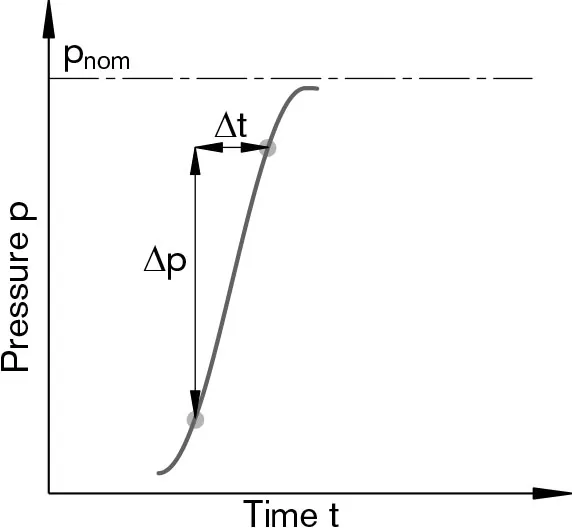
Notiz
Werte für andere Hydraulikflüssigkeiten bitten wir Sie, uns zu kontaktieren.cURL Too many subrequests by single Worker invocation. To configure this limit, refer to https://developers.cloudflare.com/workers/wrangler/configuration/#limits
Um Schäden am Axialkolbenmotor im Pumpenbetrieb (Wechsel der Hochdruckseite bei unveränderter Drehrichtung, z. B. beim Bremsen) zu verhindern, muss am Arbeitsanschluss (Einlass) ein Mindestdruck gewährleistet sein. Der Mindestdruck ist abhängig von der Drehzahl der Axialkolbeneinheit (siehe Kennlinie unten).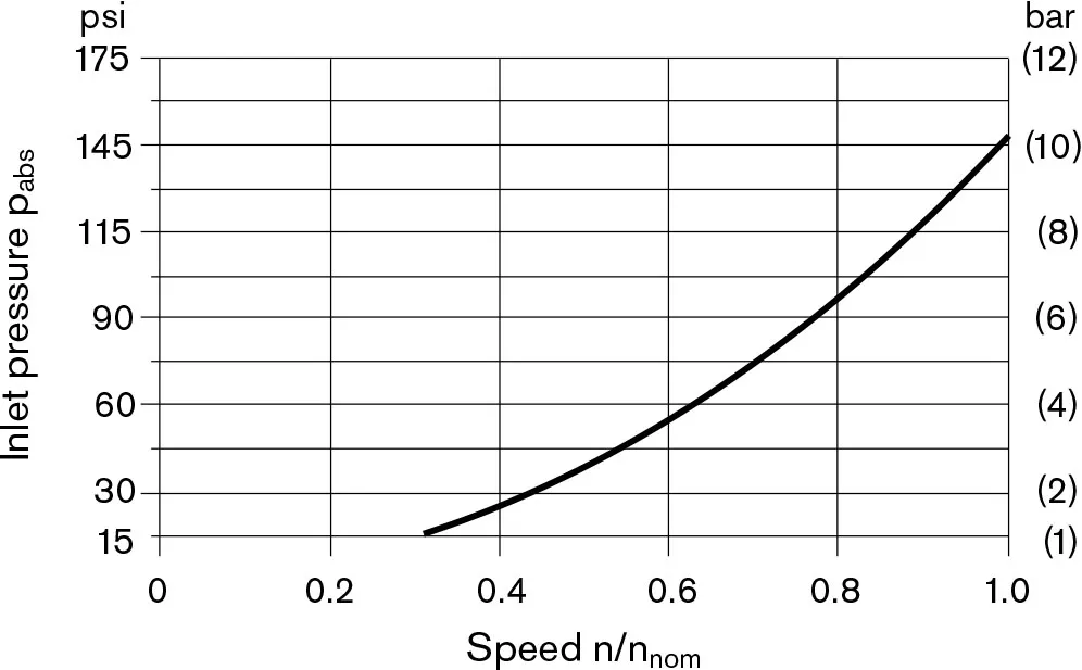 Dieses Diagramm ist nur für den optimalen Viskositätsbereich von $\nu$ gültigentscheiden = 170 bis 74 SUS (36 bis 16 mm2cURL Too many subrequests by single Worker invocation. To configure this limit, refer to https://developers.cloudflare.com/workers/wrangler/configuration/#limits.
Definition
Nenndruck Pnom Der Nenndruck entspricht dem maximalen Auslegungsdruck. Maximaler Druck PMax Der Höchstdruck entspricht dem maximalen Betriebsdruck innerhalb des einzelnen Betriebszeitraums. Die Summe der einzelnen Betriebszeiträume darf den Gesamtbetriebszeitraum nicht überschreiten. Mindestdruck (Hochdruckseite) Mindestdruck auf der Hochdruckseite (A oder B), der erforderlich ist, um Schäden an der Axialkolbeneinheit zu vermeiden. Summationsdruck pSu Der Summenöldruck ist die Summe der Drücke an beiden Arbeitsleitungsanschlüssen (A und B). Druckänderungsrate RA Maximal zulässiger Druckanstiegs- und Druckabbau-Geschwindigkeit bei einer Druckänderung über den gesamten Druckbereich.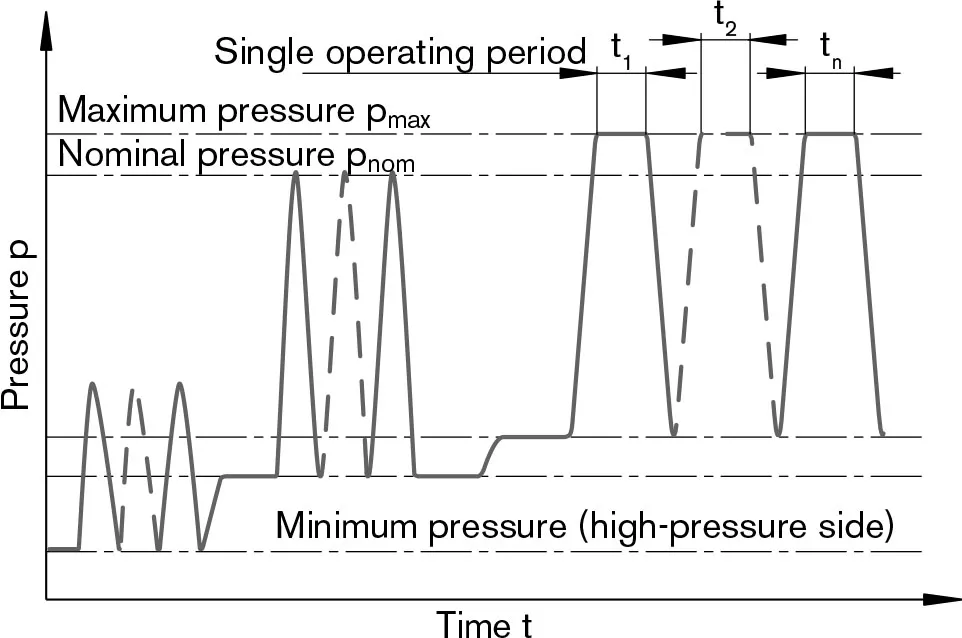 Gesamtbetriebszeit = t1 +t2cURL Too many subrequests by single Worker invocation. To configure this limit, refer to https://developers.cloudflare.com/workers/wrangler/configuration/#limitsn
Wertestabelle (theoretische Werte, ohne Wirkungsgrad und Toleranzen; Werte gerundet)
| Größe | NG | 10 | 12 | 16 | 23 | 28 | 32 | 45 | 56 | ||
| cURL Too many subrequests by single Worker invocation. To configure this limit, refer to https://developers.cloudflare.com/workers/wrangler/configuration/#limits | Vg | in3 | 0.63 | 0.73 | 0.98 | 1.40 | 1.71 | 1.95 | 2.78 | 3.42 | |
| cm3 | 10.3 | 12 | 16 | 22.9 | 28.1 | 32 | 45.6 | 56.1 | |||
| Höchstgeschwindigkeit1) | nnom | U/min | 8000 | 8000 | 8000 | 6300 | 6300 | 6300 | 5600 | 5000 | |
| nMax2) | U/min | 8800 | 8800 | 8800 | 6900 | 6900 | 6900 | 6200 | 5500 | ||
| Eingangsfluss3) | gpm | 21.8 | 25.3 | 33.9 | 38.2 | 46.8 | 53.4 | 67.4 | 74.2 | ||
| bei nnom und Vg | qv | l/min | 82 | 96 | 128 | 144 | 177 | 202 | 255 | 281 | |
| Drehmoment4) | Δp = 5100 psi | T | Pound-Feet | 42 | 49 | 66 | 94 | 116 | 132 | 188 | 231 |
| bei Vg und | Δp = 350 bar | T | Machs gut | 57 | 67 | 89 | 128 | 157 | 178 | 254 | 313 |
| Δp = 5800 psi | T | Pound-Feet | 49 | 56 | 75 | 108 | 132 | 150 | 213 | 263 | |
| Δp = 400 bar | T | Machs gut | 66 | 76 | 102 | 146 | 179 | 204 | 290 | 357 | |
| Verdrehsteifigkeit | c | kNm/rad | 0.92 | 1.25 | 1.59 | 2.56 | 2.93 | 3.12 | 4.18 | 5.94 | |
| cURL Too many subrequests by single Worker invocation. To configure this limit, refer to https://developers.cloudflare.com/workers/wrangler/configuration/#limits | JGR | Pfund-Fuß2 | 0.0095 | 0.0095 | 0.0095 | 0.0285 | 0.0285 | 0.0285 | 0.0569 | 0.0997 | |
| kgm2 | 0.0004 | 0.0004 | 0.0004 | 0.0012 | 0.0012 | 0.0012 | 0.0024 | 0.0042 | |||
| cURL Too many subrequests by single Worker invocation. To configure this limit, refer to https://developers.cloudflare.com/workers/wrangler/configuration/#limits | α | rad/s2 | 5000 | 5000 | 5000 | 6500 | 6500 | 6500 | 14600 | 7500 | |
| Fallzahl | V | Mädel | 0.045 | 0.045 | 0.045 | 0.053 | 0.053 | 0.053 | 0.087 | 0.119 | |
| L | 0.17 | 0.17 | 0.17 | 0.20 | 0.20 | 0.20 | 0.33 | 0.45 | |||
| Masse (ca.) | m | Pfund | 12 | 12 | 12 | 21 | 21 | 21 | 30 | 40 | |
| kg | 5.4 | 5.4 | 5.4 | 9.5 | 9.5 | 9.5 | 13.5 | 18 | |||
| Größe | NG | 63 | 80 | 90 | 107 | 125 | 160 | 180 | 250 | ||
| cURL Too many subrequests by single Worker invocation. To configure this limit, refer to https://developers.cloudflare.com/workers/wrangler/configuration/#limits | Vg | in3 | 3.84 | 4.91 | 5.49 | 6.51 | 7.63 | 9.79 | 10.98 | 15.25 | |
| cm3 | 63 | 80.4 | 90 | 106.7 | 125 | 160.4 | 180 | 250 | |||
| Höchstgeschwindigkeit1) | nnom | U/min | 5000 | 4500 | 4500 | 4000 | 4000 | 3600 | 3600 | 2700 | |
| nMax2) | U/min | 5500 | 5000 | 5000 | 4400 | 4400 | 4000 | 4000 | - | ||
| Eingangsfluss3) | gpm | 83.1 | 95.6 | 106.9 | 112.7 | 132.1 | 152.5 | 171.1 | 178 | ||
| bei nnom und Vg | qv | l/min | 315 | 362 | 405 | 427 | 500 | 577 | 648 | 675 | |
| Drehmoment4) | Δp = 5100 psi | T | Pound-Feet | 259 | 330 | 371 | 438 | 513 | 659 | 740 | 1030 |
| bei Vg und | Δp = 350 bar | T | Machs gut | 351 | 448 | 501 | 594 | 696 | 893 | 1003 | 1393 |
| Δp = 5800 psi | T | Pound-Feet | 296 | 378 | 423 | 501 | 587 | 753 | 845 | - | |
| Δp = 400 bar | T | Machs gut | 401 | 512 | 573 | 679 | 796 | 1021 | 1146 | - | |
| Verdrehsteifigkeit | c | kNm/rad | 6.25 | 8.73 | 9.14 | 11.2 | 11.9 | 17.4 | 18.2 | 73.1 | |
| cURL Too many subrequests by single Worker invocation. To configure this limit, refer to https://developers.cloudflare.com/workers/wrangler/configuration/#limits | JGR | Pfund-Fuß2 | 0.0997 | 0.1708 | 0.1708 | 0.2753 | 0.2753 | 0.5221 | 0.5221 | 1.4475 | |
| kgm2 | 0.0042 | 0.0072 | 0.0072 | 0.0116 | 0.0116 | 0.0220 | 0.0220 | 0.061 | |||
| cURL Too many subrequests by single Worker invocation. To configure this limit, refer to https://developers.cloudflare.com/workers/wrangler/configuration/#limits | α | rad/s2 | 7500 | 6000 | 6000 | 4500 | 4500 | 3500 | 3500 | 10000 | |
| Fallzahl | V | Mädel | 0.119 | 0.145 | 0.145 | 0.211 | 0.211 | 0.291 | 0.291 | 0.660 | |
| L | 0.45 | 0.55 | 0.55 | 0.8 | 0.8 | 1.1 | 1.1 | 2.5 | |||
| Masse (ca.) | m | Pfund | 40 | 51 | 51 | 71 | 71 | 99 | 99 | 161 | |
| kg | 18 | 23 | 23 | 32 | 32 | 45 | 45 | 73 | |||
Notiz
Der Betrieb oberhalb der Höchstwerte oder unterhalb der Mindestwerte kann zu Funktionsverlust, einer verkürzten Lebensdauer oder zur Zerstörung der Axialkolbeneinheit führen. Weitere zulässige Grenzwerte hinsichtlich Drehzahlschwankung, reduzierter Winkelbeschleunigung in Abhängigkeit von der Frequenz und der zulässigen Anlaufwinkelbeschleunigung (geringer als die maximale Winkelbeschleunigung) sind dem Datenblatt RE 90261 zu entnehmen.Bestimmung der Betriebskennlinien
| Eingangsfluss | qv=(Vg∙n)/(231∙ηv) | gpm | (qv=(Vg∙n)/(1000∙ηv) L/min) |
| Geschwindigkeit | n=(qv∙231∙ηv)/Vg | U/min | (n=(qv∙1000∙ηv)/Vg U/min |
| Drehmoment | T=(Vg∙Δp∙ηmh/(24∙π) | Pound-Feet | (T=(Vg∙Δp∙ηmh)/(20∙π) Nm) |
| Macht | P=(2π∙T∙n)/33000=(qv∙Δp∙ηt)/1714 | HP | (P=(2π∙T∙n)/60000=(qv∙Δp∙ηt)/600 kW) |
Wirkung der Radialkraft Fq über die Lebensdauer von Lagern
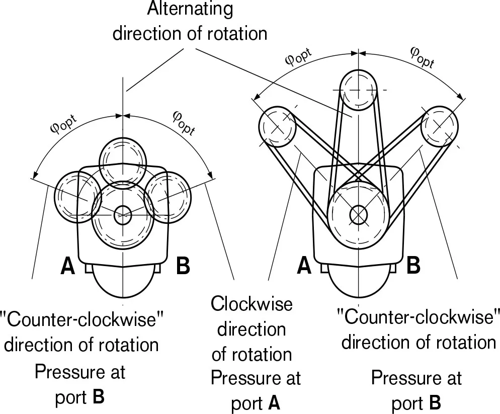
Durch Auswahl einer geeigneten Richtung der Radialkraft Fq, wird die durch die Kräfte der internen Dreheinheit verursachte Belastung der Lager verringert und somit die Lebensdauer der Lager optimiert. Die empfohlene Position des Gegenrads hängt von der Drehrichtung ab. Beispiele:| Zahnradantrieb | Keilriemenantrieb | |
| NG | φentscheiden | φentscheiden |
| 10 bis 180 | ±70° | ±45° |
| 250 | ±45° | ±70° |
Zulässige Radial- und Axialkräfte der Antriebswellen(Keilwelle und Passfederwelle)
| Größe | NG | 10 | 10 | 10 | 12 | 12 | 12 | 163) | 16 | ||
| Antriebswelle | Φ | in | 7/8 | 0.79 | 0.98 | 7/8 | 0.79 | 0.98 | 7/8 | 0.98 | |
| mm | - | 20 | 25 | - | 20 | 25 | - | 25 | |||
| Maximum radial force1) at distance a (from shaft collar) |  |
FQ-max | lbf | 629.5 | 674.4 | 719.4 | 741.9 | 674.4 | 719.4 | 966.7 | 719.4 |
| kN | 2.8 | 3.0 | 3.2 | 3.3 | 3.0 | 3.2 | 4.3 | 3.2 | |||
| a | in | 0.63 | 0.63 | 0.63 | 0.63 | 0.63 | 0.63 | 0.63 | 0.63 | ||
| mm | 16.8 | 16 | 16 | 16.8 | 16 | 16 | 16.8 | 16 | |||
| mit zulässigem Drehmoment | TMax | Pound-Feet | 47.9 | 49 | 47.9 | 56.1 | 56.1 | 56.9 | 72.3 | 73.8 | |
| Machs gut | 65 | 66 | 65 | 76 | 76 | 76 | 98 | 100 | |||
| zulässiger Druck $\Delta p$ | Δp Dauerwelle | Psi | 5800 | 5800 | 5800 | 5800 | 5800 | 5800 | 5550 | 5800 | |
| Bar | 400 | 400 | 400 | 400 | 400 | 400 | 385 | 400 | |||
| Maximale Axialkraft2) |  |
-FAch, Max | lbf | 71.9 | 71.9 | 71.9 | 71.9 | 71.9 | 71.9 | 71.9 | 71.9 |
| N | 320 | 320 | 320 | 320 | 320 | 320 | 320 | 320 | |||
| +FAch, Max | N | 0 | 0 | 0 | 0 | 0 | 0 | 0 | 0 | ||
| Permissible axial force per psi (bar) operating pressure | ±FAxt perm/bar | lbf/psi | 0.05 | 0.05 | 0.05 | 0.05 | 0.05 | 0.05 | 0.05 | 0.05 | |
| N/bar | 3.0 | 3.0 | 3.0 | 3.0 | 3.0 | 3.0 | 3.0 | 3.0 | |||
| Größe | NG | 23 | 23 | 23 | 28 | 28 | 28 | 32 | 32 | ||
| Antriebswelle | Φ | in | 1 1/4 | 0.98 | 1.18 | 1 1/4 | 0.98 | 1.18 | 1 1/4 | 1.18 | |
| mm | - | 25 | 30 | - | 25 | 30 | - | 30 | |||
| Maximum radial force1) at distance a (from shaft collar) | |
FQ-max | lbf | 809.3 | 1281.4 | 1213.9 | 989.1 | 1281.4 | 1213.9 | 1146.5 | 1213.9 |
| kN | 3.6 | 5.7 | 5.4 | 4.4 | 5.7 | 5.4 | 5.1 | 5.4 | |||
| a | in | 0.94 | 0.63 | 0.63 | 0.94 | 0.63 | 0.63 | 0.94 | 0.63 | ||
| mm | 24 | 16 | 16 | 24 | 16 | 16 | 24 | 16 | |||
| mit zulässigem Drehmoment | TMax | Pound-Feet | 106.2 | 108 | 106.2 | 131.3 | 132 | 131.3 | 150.5 | 150.5 | |
| Machs gut | 144 | 146 | 144 | 178 | 179 | 178 | 204 | 204 | |||
| zulässiger Druck $\Delta p$ | Δp Dauerwelle | Psi | 5800 | 5800 | 5800 | 5800 | 5800 | 5800 | 5800 | 5800 | |
| Bar | 400 | 400 | 400 | 400 | 400 | 400 | 400 | 400 | |||
| Maximale Axialkraft2) | |
-FAch, Max | lbf | 112.2 | 112.2 | 112.2 | 112.2 | 112.2 | 112.2 | 112.2 | 112.2 |
| N | 500 | 500 | 500 | 500 | 500 | 500 | 500 | 500 | |||
| +FAch, Max | N | 0 | 0 | 0 | 0 | 0 | 0 | 0 | 0 | ||
| Permissible axial force per psi (bar) operating pressure | ±FAxt perm/bar | lbf/psi | 0.08 | 0.08 | 0.08 | 0.08 | 0.08 | 0.08 | 0.08 | 0.08 | |
| N/bar | 5.2 | 5.2 | 5.2 | 5.2 | 5.2 | 5.2 | 5.2 | 5.2 | |||
Notiz
Influence of the direction of the permissible axial force: +FAxt Max=Increase in service life of bearings -FAxt Max= Verkürzung der Lebensdauer von Lagern (vermeiden)| Größe | NG | 45 | 45 | 563) | 56 | 56 | 56 | 633) | 63 | 63 | ||
| Antriebswelle | Φ | in | 1 1/4 | 1.18 | 1 1/4 | 1 3/8 | 1.18 | 1.37 | 1 1/4 | 1 3/8 | 1.38 | |
| mm | - | 30 | - | - | 30 | 35 | - | - | 35 | |||
| Maximum radial force1) at distance a (from shaft collar) |  |
FQ-max | lbf | 1641 | 1709 | 1709 | 2068 | 2136 | 2045 | 1708 | 2315 | 2046 |
| kN | 7.3 | 7.6 | 7.6 | 9.2 | 9.5 | 9.1 | 7.6 | 10.3 | 9.1 | |||
| a | in | 0.94 | 0.71 | 0.94 | 0.94 | 0.71 | 0.71 | 0.94 | 0.94 | 0.71 | ||
| mm | 24 | 18 | 24 | 24 | 18 | 18 | 24 | 24 | 18 | |||
| mit zulässigem Drehmoment | TMax | Pound-Feet | 214 | 214 | 223 | 263 | 263 | 263 | 223 | 295 | 295 | |
| Machs gut | 290 | 290 | 302 | 356 | 357 | 356 | 302 | 400 | 400 | |||
| zulässiger Druck $\Delta p$ | Δp Dauerwelle | Psi | 5800 | 5800 | 4950 | 5800 | 5800 | 5800 | 4350 | 5800 | 5800 | |
| Bar | 400 | 400 | 339 | 400 | 400 | 400 | 301 | 400 | 400 | |||
| Maximale Axialkraft2) |  |
-FAch, Max | lbf | 142 | 142 | 180 | 180 | 180 | 180 | 180 | 180 | 180 |
| N | 630 | 630 | 800 | 800 | 800 | 800 | 800 | 800 | 800 | |||
| +FAch, Max | N | 0 | 0 | 0 | 0 | 0 | 0 | 0 | 0 | 0 | ||
| Permissible axial force per psi (bar) operating pressure | ±FAxt perm/bar | lbf/psi | 0.11 | 0.11 | 0.13 | 0.13 | 0.13 | 0.13 | 0.13 | 0.13 | 0.13 | |
| N/bar | 7.0 | 7.0 | 8.7 | 8.7 | 8.7 | 8.7 | 8.7 | 8.7 | 8.7 | |||
| Größe | NG | 803) | 803) | 80 | 80 | 903) | 903 | 90 | 1073) | 107 | ||
| Antriebswelle | Φ | in | 1 1/4 | 1 3/8 | 1.37 | 1.57 | 1 1/4 | 1 3/8 | 1.57 | 1 1/2 | 1 3/4 | |
| mm | - | - | 35 | 40 | - | - | 40 | - | - | |||
| Maximum radial force1) at distance a (from shaft collar) | |
FQ-max | lbf | 1709 | 2608 | 2608 | 2563 | 1709 | 2608 | 2563 | 2788 | 2743 |
| kN | 7.6 | 11.6 | 11.6 | 11.4 | 7.6 | 11.6 | 11.4 | 12.4 | 12.2 | |||
| a | in | 0.94 | 0.94 | 0.79 | 0,79 | 0.94 | 0.94 | 0.79 | 1.06 | 1.32 | ||
| mm | 24 | 24 | 20 | 20 | 24 | 24 | 20 | 27 | 33.5 | |||
| mit zulässigem Drehmoment | TMax | Pound-Feet | 223 | 332 | 378 | 378 | 223 | 332 | 423 | 438 | 502 | |
| Machs gut | 302 | 450 | 512 | 512 | 302 | 450 | 573 | 594 | 680 | |||
| zulässiger Druck $\Delta p$ | Δp Dauerwelle | Psi | 3450 | 5100 | 5800 | 5800 | 3050 | 4550 | 5800 | 5100 | 5800 | |
| Bar | 237 | 352 | 400 | 400 | 211 | 314 | 400 | 349 | 400 | |||
| Maximale Axialkraft2) | |
-FAch, Max | lbf | 225 | 225 | 225 | 225 | 225 | 225 | 225 | 281 | 281 |
| N | 1000 | 1000 | 1000 | 1000 | 1000 | 1000 | 1000 | 1250 | 1250 | |||
| +FAch, Max | N | 0 | 0 | 0 | 0 | 0 | 0 | 0 | 0 | 0 | ||
| Permissible axial force per psi (bar) operating pressure | ±FAxt perm/bar | lbf/psi | 0.16 | 0.16 | 0.16 | 0.16 | 0.16 | 0.16 | 0.16 | 0.20 | 0.20 | |
| N/bar | 10.6 | 10.6 | 10.6 | 10.6 | 10.6 | 10.6 | 10.6 | 12.9 | 12.9 | |||
Notiz
Influence of the direction of the permissible axial force: +FAch, Max=Increase in service life of bearings -FAch, Max= Verkürzung der Lebensdauer von Lagern (vermeiden)| Größe | NG | 107 | 107 | 1253) | 125 | 125 | 1603) | 160 | 160 | 1803) | 180 | ||
| Antriebswelle | Φ | in | 1.57 | 1.77 | 1 1/2 | 1 3/4 | 1.77 | 1 3/4 | 1.77 | 1.97 | 1 3/4 | 1.97 | |
| mm | 40 | 45 | - | - | 45 | - | 45 | 50 | - | 50 | |||
| Maximum radial force1) at distance a (from shaft collar) | |
FQ-max | lbf | 3057 | 3169 | 2788 | 3215 | 3170 | 3350 | 4069 | 4114 | 3350 | 4114 |
| kN | 13.6 | 14.1 | 12.4 | 14.3 | 14.1 | 14.9 | 18.1 | 18.3 | 14.9 | 18.3 | |||
| a | in | 0.79 | 0.79 | 1.06 | 1.32 | 0.79 | 1.32 | 0.98 | 0.98 | 1.32 | 0.98 | ||
| mm | 20 | 20 | 27 | 33.5 | 20 | 33.5 | 25 | 25 | 33.5 | 25 | |||
| mit zulässigem Drehmoment | TMax | Pound-Feet | 501 | 502 | 438 | 587 | 587 | 611 | 753 | 749 | 611 | 844 | |
| Machs gut | 679 | 680 | 594 | 796 | 796 | 828 | 1021 | 1016 | 828 | 1144 | |||
| zulässiger Druck $\Delta p$ | Δp Dauerwelle | Psi | 5800 | 5800 | 4350 | 5800 | 5800 | 4700 | 5800 | 5800 | 4200 | 5800 | |
| Bar | 400 | 400 | 298 | 400 | 400 | 325 | 400 | 400 | 289 | 400 | |||
| Maximale Axialkraft2) | |
-FAch, Max | lbf | 281 | 281 | 281 | 281 | 281 | 360 | 360 | 360 | 360 | 360 |
| N | 1250 | 1250 | 1250 | 1250 | 1250 | 1600 | 1600 | 1600 | 1600 | 1600 | |||
| +FAch, Max | N | 0 | 0 | 0 | 0 | 0 | 0 | 0 | 0 | 0 | 0 | ||
| Permissible axial force per psi (bar) operating pressure | ±FAxt perm/bar | lbf/psi | 0.20 | 0.20 | 0.20 | 0.20 | 0.20 | 0.26 | 0.26 | 0.26 | 0.26 | 0.26 | |
| N/bar | 12.9 | 12.9 | 12.9 | 12.9 | 12.9 | 16.7 | 16.7 | 16.7 | 16.7 | 16.7 | |||
| Größe | NG | 250 | ||
| Antriebswelle | Φ | in | 1.97 | |
| mm | 50 | |||
| Maximum radial force1) at distance a (from shaft collar) | |
FQ-max | lbf | 2705) |
| kN | 1.25) | |||
| a | in | 1.61 | ||
| mm | 41 | |||
| mit zulässigem Drehmoment | TMax | Pound-Feet | 1027 | |
| Machs gut | 1393 | |||
| zulässiger Druck $\Delta p$ | Δp Dauerwelle | Psi | 5100 | |
| Bar | 350 | |||
| Maximale Axialkraft2) | |
-FAch, Max | lbf | 450 |
| N | 2000 | |||
| +FAch, Max | N | 0 | ||
| Permissible axial force per psi (bar) operating pressure | ±FAxt perm/bar | lbf/psi | 4) | |
| N/bar | ||||
Notiz
Influence of the direction of the permissible axial force: +FAch, Max = Increase in service life of bearings -FAxt Max = Verkürzung der Lebensdauer von Lagern (vermeiden)Watch AA2FM Product Video
Related Selection Resources
Request a AA2FM Quotation
Tell us your required configuration, quantity and application.
Ähnliche Produkte
Compare related hydraulic motors and confirm the complete configuration for your application.


Bestellnummer für Standardprogramm
| AA2F | M | / | 6 | W | - | V | ||||||||||
| 01 | 02 | 03 | 04 | 05 | 06 | 07 | 08 | 09 | 10 | 11 | 12 | 13 | 14 | 15 |
Hydraulikflüssigkeit
| 01 | Mineralöl und HFD. HFD für Baugrößen 250 nur in Kombination mit Langzeitfettlager "L" (ohne Kennzeichnung) | |||||||
| HFB-, HFC Hydraulikflüssigkeit |
Größen 10 bis 180 (ohne Code) | |||||||
| Größen 250 (nur in Kombination mit Long-Life-Lager "L") | E- | |||||||
Axialkolbeneinheit
| 02 | Schrägaxial-Design, Konstantpumpe/-motor, SAE-Ausführung | AA2F |
Kardanwellenlager
| 10 bis 180 | 250 | |||
| 03 | Standardlager (ohne Kennzeichnung) | ● | ● | |
| Langlebiges Lager | - | ● | L | |
Betriebsart
| 04 | Motor (Einsteckmotor A2FE, siehe RE 91008) | M |
Größe
| 05 | Geometrische Verschiebung | ||||||||
| Größe | 10 | 12 | 16 | 23 | 28 | 32 | 45 | 56 | |
| in3/rev. | 0.63 | 0.73 | 0.98 | 1.40 | 1.71 | 1.95 | 2.78 | 3.42 | |
| Größe | 63 | 80 | 90 | 107 | 125 | 160 | 180 | 250 | |
| in3/rev. | 3.84 | 4.91 | 5.49 | 6.51 | 7.63 | 9.79 | 10.98 | 15.25 | |
Serie
| 06 | 6 | |||
Index
| 07 | Größen 10 bis 180 | 1 | |
| Größe 250 | 0 |
Drehrichtung
| 08 | Auf Antriebswelle betrachtet, in beide Richtungen | W |
Robben
| 09 | FKM (Fluorkautschuk) | V |
Antriebswellen
| 10 | 12 | 16 | 23 | 28 | 32 | 45 | 56 | 63 | 80 | 90 | 107 | 125 | 160 | 180 | 250 | |||
| 10 | Kerbwelle SAE J744 (ANSI B92.1a) |
● | ● | ● | ● | ● | ● | ● | ● | ● | - | - | ● | ● | ● | ● | ● | S |
| - | - | - | - | - | - | - | ● | ● | - | - | - | - | - | - | - | T | ||
| - | - | - | - | - | - | - | - | - | ● | ● | ● | ● | - | - | - | U | ||
| - | - | - | - | - | - | - | - | - | ● | ● | - | - | - | - | - | Q | ||
| Welle mit Passfeder DIN 6885 |
● | ● | ● | ● | ● | ● | - | ● | ● | ● | ● | ● | ● | ● | ● | - | B | |
| ● | ● | - | ● | ● | - | ● | ● | - | ● | - | ● | - | ● | - | - | P | ||
| SAE-Welle mit Passfeder | - | - | - | - | - | - | - | - | - | - | - | - | - | - | - | ● | K | |
Montageflansch
| 10 | 12 | 16 | 23 | 28 | 32 | 45 | 56 | 63 | 80 | 90 | 107 | 125 | 160 | 180 | 250 | ||||
| 11 | SAE J744 | 2-Loch | ● | ● | ● | - | - | - | - | - | - | - | - | - | - | - | - | - | C |
| 4-Loch | - | - | - | ● | ● | ● | ● | ● | ● | - | - | ● | ● | ● | ● | ● | D | ||
| - | - | - | - | - | - | - | - | - | ● | ● | - | - | - | - | - | DN | |||
• = Verfügbar ○ = Auf Anfrage - = Nicht verfügbar
Anschlussplatten für Versorgungsleitungen
| 12 | SAE-Flanschanschlüsse A und B hinten1) | 51 | 0 | - | ● | ● | ● | ● | ● | ● | ● | ● | 510 | |
| SAE-Flanschanschlüsse A und B auf der Seite, gegenüber1) |
52 | 0 | - | ● | ● | ● | ● | ● | ● | ● | ● | 520 | ||
| 7 | - | ● | ● | ● | ● | ● | ● | ● | ● | 527 | ||||
| Anschlüsse A und B mit Gewinde nebenan, gegenüber1) |
53 | 0 | ● | ● | ● | - | - | - | - | - | - | 530 | ||
| Anschlüsse A und B mit Gewinde an der Seite und hinten1)2) |
54 | 0 | - | ● | ● | - | - | - | - | - | - | 540 | ||
| SAE-Flanschanschlüsse A und B am Boden1) |
60 | 0 | - | - | - | - | - | ● | ● | - | - | 600 | ||
| Anschlussplatte mit 1 Ebene Überdruckventile für Montieren eines Lasthalteventils 3)5) |
BVD 20 | 17 | 1
8 |
- | - | - | - | - | - | ● | - | - | 171 178 |
|
| 18 | - | - | ● | ● | ● | ● | ● | ● | - | 181 | ||||
| BVD/BVE 25 | 18 | - | - | - | - | - | - | - | - | -4) | 188 | |||
| Anschlussplatte mit Druckentlastungsventile5) |
19 | 1 | - | - | ● | ● | ● | ● | ● | ● | - | 191 | ||
| 2 | - | - | ● | ● | ● | ● | ● | ● | - | 192 | ||||
| Ventile | |
| Ohne Ventil | 0 |
| Mit Überdruckventil (ohne Druckerhöhungsanlage) | 1 |
| Mit Druckentlastungsventil (mit Druckerhöhungsvorrichtung) | 2 |
| Mit Spülung und Ladedruckventil, montiert | 7 |
| Senkbremsventil BVD/BVE angebaut3)6) | 8 |
| Spül- und Ladedruckventil, integriert | 9 |
Geschwindigkeitssensoren
| 10 bis 16 | 23 bis 32 | 45 | 56 bis 90 | 107 bis 180 | 250 | |||
| 13 | Ohne Geschwindigkeitssensor (ohne Code) | ● | ● | ● | ● | ● | ● | |
| Vorbereitet für Festplatten-geschwindigkeitssensor | - | ▲ | ▲ | ▲ | ▲ | - | F | |
| Festplattengeschwindigkeitssensor montiert7) | - | ▲ | ▲ | ▲ | ▲ | - | H | |
| Vorbereitet für DSM/DSA-Geschwindigkeitssensor | - | ● | ● | ● | ● | - | U | |
| DSM/DSA-Geschwindigkeitssensor montiert7) | - | ● | ● | ● | ● | - | V | |
Sonderversion
| 14 | Standardversion (ohne Code) | |
| Sonderausführung für Schwenkantriebe (standardmäßig mit Anschlussplatte 19) | J |
Standard- / Sonderversion
| 15 | Standardversion (ohne Code) | |
| Standardversion mit Installationsvarianten, z. B. T-Bohrungen gegen Standard offen oder geschlossen | -Y | |
| Sonderversion | -S |
•=Verfügbar ○=Auf Anfrage -=Nicht verfügbar ▲=Nicht für Neuprojekte
1. Befestigungsgewinde oder Gewindeanschlüsse sind SAE (UN/UNF)
2. Seitliche Gewindeanschlüsse (Baugrößen 10 bis 63) mit Gewindestopfen verschlossen
3. Beachten Sie die Einschränkungen auf Seite 32.
4. Bitte kontaktieren Sie uns.
5. Befestigungsgewinde und Gewindeanschlüsse sind metrisch
6. Geben Sie den Bestellschlüssel für das entsperrbare Rückschlagventil gemäß Datenblatt (BVD-RE 95522, BVE-RE 95525) separat an.
Geben Sie den Bestellcode des Sensors gemäß Datenblatt (DSM-RE 95132, DSA-RE 95133, HDD-RE 95135) separat an und beachten Sie die Anforderungen an die Elektronik
Technische Daten
Hydraulikflüssigkeit
Vor Beginn der Projektplanung beachten Sie bitte unsere Datenblätter RE 90220 (Mineralöl), RE 90221 (umweltverträgliche Hydraulikflüssigkeiten), RE 90222 (HFD-Hydraulikflüssigkeiten) und RE 90223 (HFA-, HFB-, HFC-Hydraulikflüssigkeiten) bezüglich detaillierter Angaben zur Auswahl der Hydraulikflüssigkeit und der Einsatzbedingungen.
Der Schrägachsen-Konstantmotor AA2FM ist nicht für den Betrieb mit HFA-Hydraulikflüssigkeit geeignet. Bei Verwendung von HFB-, HFC- oder HFD-Hydraulikflüssigkeiten oder umweltverträglichen Hydraulikflüssigkeiten müssen die Einschränkungen bezüglich der technischen Daten oder anderer Dichtungen beachtet werden.
Auswahldiagramm
Viskosität und Temperatur von Hydraulikflüssigkeit
| Viskosität [SUS (mm2/s)] |
Temperatur | Kommentar | |
| Transport und Lagerung bei Raumtemperatur |
Tmin. ≥ -58 ℉ (-50 ℃) | Werkskonservierung: bis zu 12 Monate mit Standard, bis zu 24 Monate mit Langzeit- |
|
| Tentscheiden = +41 ℉ bis +68 ℉ (+5℃ bis +20℃) |
|||
| Kaltstart1) | VMax=7400(1600) | TSt.≥ -40℉ (-40℃) | t ≤ 3 min, ohne Last (p ≤ 725 psi (50 bar)), |
| n ≤ 1000 U/min (für Baugrößen 10 bis 180), | |||
| n ≤ 0,25 · nnom (für Größen 250) | |||
| Zulässiger Temperaturunterschied | ΔT ≤ 45 ℉ (25 ℃) | zwischen Axialkolbeneinheit und Hydraulikflüssigkeit | |
| Aufwärmphase | ν<7400 bis 1850 (1600 bis 400) |
T = -40 ℉ bis -13 ℉ (-40 °C bis -25 °C) |
bei p ≤ 0,7·Pnom, n ≤ 0,5·nnom und t ≤ 15 min |
| Betriebsphase | |||
| Temperaturdifferenz | ΔT = ca. 22 ℉ (12 ℃) | zwischen der Hydraulikflüssigkeit im Lager und am Anschluss T. | |
| Höchsttemperatur | +240℉ (115℃) | im Lager | |
| +217 ℉ (103 ℃) | am Anschluss T gemessen | ||
| Dauerbetrieb | v=1850 bis 47 | T = -13 ℉ bis +195 ℉ | gemessen an Anschluss T, |
| (400 bis 10) | (-25℃ bis +90℃) | keine Einschränkung innerhalb der zulässigen Daten | |
| Ventscheiden = 170 bis 74 (36 bis 16) |
|||
| Kurzzeitbetrieb2) | Vmin.≥32 (7) | TMax= +217℉ (+103℃) | gemessen an Anschluss T, t < 3 min, p < 0,3·Pnom |
| FKM-Wellendichtring1) | T≤ +240℉ (+115℃) | siehe Seite 5 | |
| 1) Bei Temperaturen unter -13 ℉ (-25 ℃) ist ein NBR-Wellendichtring erforderlich. (zulässiger Temperaturbereich: -40 ℉ bis +195 ℉ (-40 ℃ bis +90 ℃)). |
|||
| 2) Größen 250, bitte kontaktieren Sie uns. | |||
Einzelheiten zur Auswahl der Hydraulikflüssigkeit
Die korrekte Wahl der Hydraulikflüssigkeit erfordert die Kenntnis der Betriebstemperatur im Verhältnis zur Umgebungstemperatur: im geschlossenen Kreislauf die Kreislauftemperatur, im offenen Kreislauf die Behältertemperatur.
Die Hydraulikflüssigkeit sollte so ausgewählt werden, dass die Betriebsviskosität im Betriebstemperaturbereich im optimalen Bereich liegt (νentscheiden (siehe schattierter Bereich im Auswahldiagramm). Wir empfehlen, in jedem Fall die höhere Viskositätsklasse zu wählen.
Beispiel: Bei einer Umgebungstemperatur von X ℉ (X ℃) wird im Schaltkreis eine Betriebstemperatur von 140 ℉ (60 ℃) eingestellt. Im optimalen Betriebsviskositätsbereich (νOPt, schattierter Bereich), entspricht dies den Viskositätsklassen VG 46 oder VG 68; auszuwählen ist: VG 68.
Notiz
Die Gehäuseleckagetemperatur, die durch Druck und Drehzahl beeinflusst wird, kann höher sein als die Kreislauftemperatur oder die Behältertemperatur. Die Temperatur darf an keinem Punkt der Komponente höher als 240℉ (115℃) sein. Die unten angegebene Temperaturdifferenz ist bei der Bestimmung der Viskosität im Lager zu berücksichtigen.
Wenn die vorgenannten Bedingungen aufgrund extremer Betriebsparameter nicht eingehalten werden können, empfehlen wir das Spülen des Gehäuses an Anschluss U (Größe 250) oder die Verwendung eines Spül- und Speisedruckventils.
Filtration der Hydraulikflüssigkeit
Eine feiner ausgelegte Filtration verbessert den Reinheitsgrad der Hydraulikflüssigkeit, wodurch sich die Lebensdauer der Axialkolbeneinheit erhöht.
Zur Sicherstellung der Funktionssicherheit der Axialkolbeneinheit ist eine gravimetrische Analyse der Hydraulikflüssigkeit erforderlich, um die Menge an Feststoffverunreinigungen zu bestimmen und die Reinheitsklasse gemäß ISO 4406 zu ermitteln. Dabei ist eine Reinheitsklasse von mindestens 20/18/15 einzuhalten.
Bei sehr hohen Hydraulikflüssigkeitstemperaturen (+195℉ bis +240℉ (90℃ bis maximal 115℃)) ist ein Reinheitsgrad von mindestens 19/17/14 gemäß ISO 4406 erforderlich.
Wenn die oben genannten Klassen nicht erreicht werden können, kontaktieren Sie uns bitte.
Wellendichtung
Zulässige Druckbelastung
Die Lebensdauer des Wellendichtrings wird durch die Drehzahl der Axialkolbeneinheit und den Gehäusedruck beeinflusst. Der mittlere Differenzdruck von 30 psi (2 bar) zwischen Gehäuse und Umgebungsdruck darf bei normaler Betriebstemperatur nicht dauerhaft überschritten werden. Für einen höheren Differenzdruck bei reduzierter Drehzahl siehe Diagramm. Kurzzeitige Druckspitzen (t < 0,1 s) von bis zu 145 psi (10 bar) sind zulässig. Die Lebensdauer des Wellendichtrings nimmt mit zunehmender Häufigkeit von Druckspitzen ab.
Der Gehäusedruck muss gleich dem Umgebungsdruck oder höher als dieser sein.
Die Werte gelten für einen Umgebungsdruck
PABS = 15 psi (1 bar).
Temperaturbereich
Der FKM-Wellendichtring kann für Gehäusedrücklauftemperaturen von -13 ℉ bis +240 ℉ (-25 ℃ bis +115 ℃) verwendet werden.
Notiz
Für Einsatzfälle unter -13℉ (-25℃) ist ein NBR-Wellendichtring erforderlich (zulässiger Temperaturbereich: -40℉ bis 195℉ (-40℃ bis +90℃)). NBR-Wellendichtring bei der Bestellung im Klartext angeben.
Bitte kontaktieren Sie uns.
Fließrichtung
| Drehrichtung, gesehen auf Antriebswelle | |
| im Uhrzeigersinn | gegen den Uhrzeigersinn |
| Von A nach B | B zu A |
Geschwindigkeitsbereich
Keine Begrenzung der Mindestdrehzahl nmin.. Wenn eine gleichförmige Bewegung erforderlich ist, die Drehzahl nmin. darf nicht weniger als 50 U/min betragen. Siehe Wertetabelle auf Seite 7 für die Höchstgeschwindigkeit.
Langlebiges Lager
Größe 250
Für lange Lebensdauer und den Einsatz mit HF-Flüssigkeiten. Identische Außenabmessungen wie Motoren mit Standardlagern. Nachträglicher Umbau auf Long-Life-Lager ist möglich. Lager- und Gehäusespülung über Anschluss U wird empfohlen.
Spülstrom (empfohlen)
| Größe | 250 | |
| qflächenbündig | gpm | 2.6 |
| l/min | 10 |
Betriebsdruckbereich
(mit Mineralöl betrieben)
Druck am Arbeitsanschluss A oder B
Größen 10 bis 180
Nenndruck pnom______________5800 psi (400 bar) absolut
Maximaler Druck pMax______________6500 psi (450 bar) absolut
Einzelne Betriebsdauer__________________10s
Gesamtbetriebsdauer___________________300h
Summationsdruck (Druck A + Druck B)pSu_____________10.150 psi (700 bar)
Größen 250
Nenndruck pnom____________5100 psi (350 bar) absolut
Maximaler Druck pMax____________5800 psi (400 bar) absolut
Einzelne Betriebsdauer__________________10s
Gesamtbetriebszeit__________________300h
Summationsdruck (Druck A + Druck B) psu___________10150 psi (700 bar)
Mindestdruck (Hochdruckseite)365 psi (25 bar) absolut
Druckänderungsrate RA Max
mit integriertem Druckbegrenzungsventil___________130000 psi/s (9000 bar/s)
ohne Überdruckventil______________232000 psi/s (16000 bar/s)
Notiz
Werte für andere Hydraulikflüssigkeiten bitten wir Sie, uns zu kontaktieren.
Mindestdruck – Pumpenbetrieb (Einlass)
Um Schäden am Axialkolbenmotor im Pumpenbetrieb (Wechsel der Hochdruckseite bei unveränderter Drehrichtung, z. B. beim Bremsen) zu verhindern, muss am Arbeitsanschluss (Einlass) ein Mindestdruck gewährleistet sein. Der Mindestdruck ist abhängig von der Drehzahl der Axialkolbeneinheit (siehe Kennlinie unten).
Dieses Diagramm ist nur für den optimalen Viskositätsbereich von $\nu$ gültigentscheiden = 170 bis 74 SUS (36 bis 16 mm2/s).
Bitte kontaktieren Sie uns, wenn diese Bedingungen nicht erfüllt werden können.
Definition
Nenndruck Pnom
Der Nenndruck entspricht dem maximalen Auslegungsdruck.
Maximaler Druck PMax
Der Höchstdruck entspricht dem maximalen Betriebsdruck innerhalb des einzelnen Betriebszeitraums. Die Summe der einzelnen Betriebszeiträume darf den Gesamtbetriebszeitraum nicht überschreiten.
Mindestdruck (Hochdruckseite)
Mindestdruck auf der Hochdruckseite (A oder B), der erforderlich ist, um Schäden an der Axialkolbeneinheit zu vermeiden.
Summationsdruck pSu
Der Summenöldruck ist die Summe der Drücke an beiden Arbeitsleitungsanschlüssen (A und B).
Druckänderungsrate RA
Maximal zulässiger Druckanstiegs- und Druckabbau-Geschwindigkeit bei einer Druckänderung über den gesamten Druckbereich.
Gesamtbetriebszeit = t1 +t2+... +tn
Wertestabelle (theoretische Werte, ohne Wirkungsgrad und Toleranzen; Werte gerundet)
| Größe | NG | 10 | 12 | 16 | 23 | 28 | 32 | 45 | 56 | ||
| Geometrische Verdrängung, pro Umdrehung |
Vg | in3 | 0.63 | 0.73 | 0.98 | 1.40 | 1.71 | 1.95 | 2.78 | 3.42 | |
| cm3 | 10.3 | 12 | 16 | 22.9 | 28.1 | 32 | 45.6 | 56.1 | |||
| Höchstgeschwindigkeit1) | nnom | U/min | 8000 | 8000 | 8000 | 6300 | 6300 | 6300 | 5600 | 5000 | |
| nMax2) | U/min | 8800 | 8800 | 8800 | 6900 | 6900 | 6900 | 6200 | 5500 | ||
| Eingangsfluss3) | gpm | 21.8 | 25.3 | 33.9 | 38.2 | 46.8 | 53.4 | 67.4 | 74.2 | ||
| bei nnom und Vg | qv | l/min | 82 | 96 | 128 | 144 | 177 | 202 | 255 | 281 | |
| Drehmoment4) | Δp = 5100 psi | T | Pound-Feet | 42 | 49 | 66 | 94 | 116 | 132 | 188 | 231 |
| bei Vg und | Δp = 350 bar | T | Machs gut | 57 | 67 | 89 | 128 | 157 | 178 | 254 | 313 |
| Δp = 5800 psi | T | Pound-Feet | 49 | 56 | 75 | 108 | 132 | 150 | 213 | 263 | |
| Δp = 400 bar | T | Machs gut | 66 | 76 | 102 | 146 | 179 | 204 | 290 | 357 | |
| Verdrehsteifigkeit | c | kNm/rad | 0.92 | 1.25 | 1.59 | 2.56 | 2.93 | 3.12 | 4.18 | 5.94 | |
| Trägheitsmoment für Drehgruppe |
JGR | Pfund-Fuß2 | 0.0095 | 0.0095 | 0.0095 | 0.0285 | 0.0285 | 0.0285 | 0.0569 | 0.0997 | |
| kgm2 | 0.0004 | 0.0004 | 0.0004 | 0.0012 | 0.0012 | 0.0012 | 0.0024 | 0.0042 | |||
| Maximaler Winkel Beschleunigung |
α | rad/s2 | 5000 | 5000 | 5000 | 6500 | 6500 | 6500 | 14600 | 7500 | |
| Fallzahl | V | Mädel | 0.045 | 0.045 | 0.045 | 0.053 | 0.053 | 0.053 | 0.087 | 0.119 | |
| L | 0.17 | 0.17 | 0.17 | 0.20 | 0.20 | 0.20 | 0.33 | 0.45 | |||
| Masse (ca.) | m | Pfund | 12 | 12 | 12 | 21 | 21 | 21 | 30 | 40 | |
| kg | 5.4 | 5.4 | 5.4 | 9.5 | 9.5 | 9.5 | 13.5 | 18 | |||
| Größe | NG | 63 | 80 | 90 | 107 | 125 | 160 | 180 | 250 | ||
| Geometrische Verdrängung, pro Umdrehung |
Vg | in3 | 3.84 | 4.91 | 5.49 | 6.51 | 7.63 | 9.79 | 10.98 | 15.25 | |
| cm3 | 63 | 80.4 | 90 | 106.7 | 125 | 160.4 | 180 | 250 | |||
| Höchstgeschwindigkeit1) | nnom | U/min | 5000 | 4500 | 4500 | 4000 | 4000 | 3600 | 3600 | 2700 | |
| nMax2) | U/min | 5500 | 5000 | 5000 | 4400 | 4400 | 4000 | 4000 | - | ||
| Eingangsfluss3) | gpm | 83.1 | 95.6 | 106.9 | 112.7 | 132.1 | 152.5 | 171.1 | 178 | ||
| bei nnom und Vg | qv | l/min | 315 | 362 | 405 | 427 | 500 | 577 | 648 | 675 | |
| Drehmoment4) | Δp = 5100 psi | T | Pound-Feet | 259 | 330 | 371 | 438 | 513 | 659 | 740 | 1030 |
| bei Vg und | Δp = 350 bar | T | Machs gut | 351 | 448 | 501 | 594 | 696 | 893 | 1003 | 1393 |
| Δp = 5800 psi | T | Pound-Feet | 296 | 378 | 423 | 501 | 587 | 753 | 845 | - | |
| Δp = 400 bar | T | Machs gut | 401 | 512 | 573 | 679 | 796 | 1021 | 1146 | - | |
| Verdrehsteifigkeit | c | kNm/rad | 6.25 | 8.73 | 9.14 | 11.2 | 11.9 | 17.4 | 18.2 | 73.1 | |
| Trägheitsmoment für Drehgruppe |
JGR | Pfund-Fuß2 | 0.0997 | 0.1708 | 0.1708 | 0.2753 | 0.2753 | 0.5221 | 0.5221 | 1.4475 | |
| kgm2 | 0.0042 | 0.0072 | 0.0072 | 0.0116 | 0.0116 | 0.0220 | 0.0220 | 0.061 | |||
| Maximaler Winkel Beschleunigung |
α | rad/s2 | 7500 | 6000 | 6000 | 4500 | 4500 | 3500 | 3500 | 10000 | |
| Fallzahl | V | Mädel | 0.119 | 0.145 | 0.145 | 0.211 | 0.211 | 0.291 | 0.291 | 0.660 | |
| L | 0.45 | 0.55 | 0.55 | 0.8 | 0.8 | 1.1 | 1.1 | 2.5 | |||
| Masse (ca.) | m | Pfund | 40 | 51 | 51 | 71 | 71 | 99 | 99 | 161 | |
| kg | 18 | 23 | 23 | 32 | 32 | 45 | 45 | 73 | |||
1) Die Werte sind gültig:
- für den optimalen Viskositätsbereich von
νentscheiden = 170 bis 74 SUS (36 bis 16 mm2/s)
- mit Hydraulikflüssigkeit auf Mineralölbasis
2) Zulässige kurzzeitige Höchstdrehzahl: Überdrehzahl bei Entlastungs- und Senkvorgängen, t <5 s und Δp <2200 psi (150 bar)
3) Einschränkung des Zulaufstroms mit Rückschlag-Drosselventil, siehe Seite 32
4) Drehmoment ohne Radialkraft, mit Radialkraft siehe Seite 9
Notiz
Der Betrieb oberhalb der Höchstwerte oder unterhalb der Mindestwerte kann zu Funktionsverlust, einer verkürzten Lebensdauer oder zur Zerstörung der Axialkolbeneinheit führen. Weitere zulässige Grenzwerte hinsichtlich Drehzahlschwankung, reduzierter Winkelbeschleunigung in Abhängigkeit von der Frequenz und der zulässigen Anlaufwinkelbeschleunigung (geringer als die maximale Winkelbeschleunigung) sind dem Datenblatt RE 90261 zu entnehmen.
Bestimmung der Betriebskennlinien
| Eingangsfluss | qv=(Vg∙n)/(231∙ηv) | gpm | (qv=(Vg∙n)/(1000∙ηv) L/min) |
| Geschwindigkeit | n=(qv∙231∙ηv)/Vg | U/min | (n=(qv∙1000∙ηv)/Vg U/min |
| Drehmoment | T=(Vg∙Δp∙ηmh/(24∙π) | Pound-Feet | (T=(Vg∙Δp∙ηmh)/(20∙π) Nm) |
| Macht | P=(2π∙T∙n)/33000=(qv∙Δp∙ηt)/1714 | HP | (P=(2π∙T∙n)/60000=(qv∙Δp∙ηt)/600 kW) |
Vg = Hubraum pro Umdrehung in in3 (cm3)
Δp = Differenzdruck in psi (bar)
n = Drehzahl in U/min
ηv= Volumetrischer Wirkungsgrad
ηmh Mechanisch-hydraulischer Wirkungsgrad
ηt = Gesamtwirkungsgrad (ηt=ηt∙ηmn)
Wirkung der Radialkraft Fq über die Lebensdauer von Lagern
Durch Auswahl einer geeigneten Richtung der Radialkraft Fq, wird die durch die Kräfte der internen Dreheinheit verursachte Belastung der Lager verringert und somit die Lebensdauer der Lager optimiert. Die empfohlene Position des Gegenrads hängt von der Drehrichtung ab. Beispiele:
| Zahnradantrieb | Keilriemenantrieb | |
| NG | φentscheiden | φentscheiden |
| 10 bis 180 | ±70° | ±45° |
| 250 | ±45° | ±70° |
Zulässige Radial- und Axialkräfte der Antriebswellen(Keilwelle und Passfederwelle)
| Größe | NG | 10 | 10 | 10 | 12 | 12 | 12 | 163) | 16 | ||
| Antriebswelle | Φ | in | 7/8 | 0.79 | 0.98 | 7/8 | 0.79 | 0.98 | 7/8 | 0.98 | |
| mm | - | 20 | 25 | - | 20 | 25 | - | 25 | |||
| Maximum Radiale Kraft1) in der Entfernung a (von Stellring) |
|
FQ-max | lbf | 629.5 | 674.4 | 719.4 | 741.9 | 674.4 | 719.4 | 966.7 | 719.4 |
| kN | 2.8 | 3.0 | 3.2 | 3.3 | 3.0 | 3.2 | 4.3 | 3.2 | |||
| a | in | 0.63 | 0.63 | 0.63 | 0.63 | 0.63 | 0.63 | 0.63 | 0.63 | ||
| mm | 16.8 | 16 | 16 | 16.8 | 16 | 16 | 16.8 | 16 | |||
| mit zulässigem Drehmoment | TMax | Pound-Feet | 47.9 | 49 | 47.9 | 56.1 | 56.1 | 56.9 | 72.3 | 73.8 | |
| Machs gut | 65 | 66 | 65 | 76 | 76 | 76 | 98 | 100 | |||
| zulässiger Druck $\Delta p$ | Δp Dauerwelle | Psi | 5800 | 5800 | 5800 | 5800 | 5800 | 5800 | 5550 | 5800 | |
| Bar | 400 | 400 | 400 | 400 | 400 | 400 | 385 | 400 | |||
| Maximale Axialkraft2) | |
-FAch, Max | lbf | 71.9 | 71.9 | 71.9 | 71.9 | 71.9 | 71.9 | 71.9 | 71.9 |
| N | 320 | 320 | 320 | 320 | 320 | 320 | 320 | 320 | |||
| +FAch, Max | N | 0 | 0 | 0 | 0 | 0 | 0 | 0 | 0 | ||
| Zulässige Axialkraft pro psi (bar) Betriebsdruck |
±FAxt perm/bar | lbf/psi | 0.05 | 0.05 | 0.05 | 0.05 | 0.05 | 0.05 | 0.05 | 0.05 | |
| N/bar | 3.0 | 3.0 | 3.0 | 3.0 | 3.0 | 3.0 | 3.0 | 3.0 | |||
| Größe | NG | 23 | 23 | 23 | 28 | 28 | 28 | 32 | 32 | ||
| Antriebswelle | Φ | in | 1 1/4 | 0.98 | 1.18 | 1 1/4 | 0.98 | 1.18 | 1 1/4 | 1.18 | |
| mm | - | 25 | 30 | - | 25 | 30 | - | 30 | |||
| Maximum Radiale Kraft1) in der Entfernung a (von Stellring) |
|
FQ-max | lbf | 809.3 | 1281.4 | 1213.9 | 989.1 | 1281.4 | 1213.9 | 1146.5 | 1213.9 |
| kN | 3.6 | 5.7 | 5.4 | 4.4 | 5.7 | 5.4 | 5.1 | 5.4 | |||
| a | in | 0.94 | 0.63 | 0.63 | 0.94 | 0.63 | 0.63 | 0.94 | 0.63 | ||
| mm | 24 | 16 | 16 | 24 | 16 | 16 | 24 | 16 | |||
| mit zulässigem Drehmoment | TMax | Pound-Feet | 106.2 | 108 | 106.2 | 131.3 | 132 | 131.3 | 150.5 | 150.5 | |
| Machs gut | 144 | 146 | 144 | 178 | 179 | 178 | 204 | 204 | |||
| zulässiger Druck $\Delta p$ | Δp Dauerwelle | Psi | 5800 | 5800 | 5800 | 5800 | 5800 | 5800 | 5800 | 5800 | |
| Bar | 400 | 400 | 400 | 400 | 400 | 400 | 400 | 400 | |||
| Maximale Axialkraft2) | |
-FAch, Max | lbf | 112.2 | 112.2 | 112.2 | 112.2 | 112.2 | 112.2 | 112.2 | 112.2 |
| N | 500 | 500 | 500 | 500 | 500 | 500 | 500 | 500 | |||
| +FAch, Max | N | 0 | 0 | 0 | 0 | 0 | 0 | 0 | 0 | ||
| Zulässige Axialkraft pro psi (bar) Betriebsdruck |
±FAxt perm/bar | lbf/psi | 0.08 | 0.08 | 0.08 | 0.08 | 0.08 | 0.08 | 0.08 | 0.08 | |
| N/bar | 5.2 | 5.2 | 5.2 | 5.2 | 5.2 | 5.2 | 5.2 | 5.2 | |||
1) Bei Aussetzbetrieb
2) Maximal zulässige Axialkraft im Stillstand oder beim Betrieb der Axialkolbeneinheit im drucklosen Zustand.
3) Beschränkte technische Daten
Notiz
Einfluss der Richtung der zulässigen Axialkraft:
+FAxt MaxErhöhung der Lebensdauer von Lagern
-FAxt Max= Verkürzung der Lebensdauer von Lagern (vermeiden)
| Größe | NG | 45 | 45 | 563) | 56 | 56 | 56 | 633) | 63 | 63 | ||
| Antriebswelle | Φ | in | 1 1/4 | 1.18 | 1 1/4 | 1 3/8 | 1.18 | 1.37 | 1 1/4 | 1 3/8 | 1.38 | |
| mm | - | 30 | - | - | 30 | 35 | - | - | 35 | |||
| Maximum Radiale Kraft1) in der Entfernung a (von Stellring) |
|
FQ-max | lbf | 1641 | 1709 | 1709 | 2068 | 2136 | 2045 | 1708 | 2315 | 2046 |
| kN | 7.3 | 7.6 | 7.6 | 9.2 | 9.5 | 9.1 | 7.6 | 10.3 | 9.1 | |||
| a | in | 0.94 | 0.71 | 0.94 | 0.94 | 0.71 | 0.71 | 0.94 | 0.94 | 0.71 | ||
| mm | 24 | 18 | 24 | 24 | 18 | 18 | 24 | 24 | 18 | |||
| mit zulässigem Drehmoment | TMax | Pound-Feet | 214 | 214 | 223 | 263 | 263 | 263 | 223 | 295 | 295 | |
| Machs gut | 290 | 290 | 302 | 356 | 357 | 356 | 302 | 400 | 400 | |||
| zulässiger Druck $\Delta p$ | Δp Dauerwelle | Psi | 5800 | 5800 | 4950 | 5800 | 5800 | 5800 | 4350 | 5800 | 5800 | |
| Bar | 400 | 400 | 339 | 400 | 400 | 400 | 301 | 400 | 400 | |||
| Maximale Axialkraft2) | |
-FAch, Max | lbf | 142 | 142 | 180 | 180 | 180 | 180 | 180 | 180 | 180 |
| N | 630 | 630 | 800 | 800 | 800 | 800 | 800 | 800 | 800 | |||
| +FAch, Max | N | 0 | 0 | 0 | 0 | 0 | 0 | 0 | 0 | 0 | ||
| Zulässige Axialkraft pro psi (bar) Betriebsdruck |
±FAxt perm/bar | lbf/psi | 0.11 | 0.11 | 0.13 | 0.13 | 0.13 | 0.13 | 0.13 | 0.13 | 0.13 | |
| N/bar | 7.0 | 7.0 | 8.7 | 8.7 | 8.7 | 8.7 | 8.7 | 8.7 | 8.7 | |||
| Größe | NG | 803) | 803) | 80 | 80 | 903) | 903 | 90 | 1073) | 107 | ||
| Antriebswelle | Φ | in | 1 1/4 | 1 3/8 | 1.37 | 1.57 | 1 1/4 | 1 3/8 | 1.57 | 1 1/2 | 1 3/4 | |
| mm | - | - | 35 | 40 | - | - | 40 | - | - | |||
| Maximum Radiale Kraft1) in der Entfernung a (von Stellring) |
|
FQ-max | lbf | 1709 | 2608 | 2608 | 2563 | 1709 | 2608 | 2563 | 2788 | 2743 |
| kN | 7.6 | 11.6 | 11.6 | 11.4 | 7.6 | 11.6 | 11.4 | 12.4 | 12.2 | |||
| a | in | 0.94 | 0.94 | 0.79 | 0,79 | 0.94 | 0.94 | 0.79 | 1.06 | 1.32 | ||
| mm | 24 | 24 | 20 | 20 | 24 | 24 | 20 | 27 | 33.5 | |||
| mit zulässigem Drehmoment | TMax | Pound-Feet | 223 | 332 | 378 | 378 | 223 | 332 | 423 | 438 | 502 | |
| Machs gut | 302 | 450 | 512 | 512 | 302 | 450 | 573 | 594 | 680 | |||
| zulässiger Druck $\Delta p$ | Δp Dauerwelle | Psi | 3450 | 5100 | 5800 | 5800 | 3050 | 4550 | 5800 | 5100 | 5800 | |
| Bar | 237 | 352 | 400 | 400 | 211 | 314 | 400 | 349 | 400 | |||
| Maximale Axialkraft2) | |
-FAch, Max | lbf | 225 | 225 | 225 | 225 | 225 | 225 | 225 | 281 | 281 |
| N | 1000 | 1000 | 1000 | 1000 | 1000 | 1000 | 1000 | 1250 | 1250 | |||
| +FAch, Max | N | 0 | 0 | 0 | 0 | 0 | 0 | 0 | 0 | 0 | ||
| Zulässige Axialkraft pro psi (bar) Betriebsdruck |
±FAxt perm/bar | lbf/psi | 0.16 | 0.16 | 0.16 | 0.16 | 0.16 | 0.16 | 0.16 | 0.20 | 0.20 | |
| N/bar | 10.6 | 10.6 | 10.6 | 10.6 | 10.6 | 10.6 | 10.6 | 12.9 | 12.9 | |||
1. Bei Aussetzbetrieb
2. Maximal zulässige Axialkraft im Stillstand oder wenn die Axialkolbeneinheit im drucklosen Zustand betrieben wird.
3. Beschränkte technische Daten
Notiz
Einfluss der Richtung der zulässigen Axialkraft:
+FAch, MaxErhöhung der Lebensdauer von Lagern
-FAch, Max= Verkürzung der Lebensdauer von Lagern (vermeiden)
| Größe | NG | 107 | 107 | 1253) | 125 | 125 | 1603) | 160 | 160 | 1803) | 180 | ||
| Antriebswelle | Φ | in | 1.57 | 1.77 | 1 1/2 | 1 3/4 | 1.77 | 1 3/4 | 1.77 | 1.97 | 1 3/4 | 1.97 | |
| mm | 40 | 45 | - | - | 45 | - | 45 | 50 | - | 50 | |||
| Maximum Radiale Kraft1) in der Entfernung a (von Stellring) |
|
FQ-max | lbf | 3057 | 3169 | 2788 | 3215 | 3170 | 3350 | 4069 | 4114 | 3350 | 4114 |
| kN | 13.6 | 14.1 | 12.4 | 14.3 | 14.1 | 14.9 | 18.1 | 18.3 | 14.9 | 18.3 | |||
| a | in | 0.79 | 0.79 | 1.06 | 1.32 | 0.79 | 1.32 | 0.98 | 0.98 | 1.32 | 0.98 | ||
| mm | 20 | 20 | 27 | 33.5 | 20 | 33.5 | 25 | 25 | 33.5 | 25 | |||
| mit zulässigem Drehmoment | TMax | Pound-Feet | 501 | 502 | 438 | 587 | 587 | 611 | 753 | 749 | 611 | 844 | |
| Machs gut | 679 | 680 | 594 | 796 | 796 | 828 | 1021 | 1016 | 828 | 1144 | |||
| zulässiger Druck $\Delta p$ | Δp Dauerwelle | Psi | 5800 | 5800 | 4350 | 5800 | 5800 | 4700 | 5800 | 5800 | 4200 | 5800 | |
| Bar | 400 | 400 | 298 | 400 | 400 | 325 | 400 | 400 | 289 | 400 | |||
| Maximale Axialkraft2) | |
-FAch, Max | lbf | 281 | 281 | 281 | 281 | 281 | 360 | 360 | 360 | 360 | 360 |
| N | 1250 | 1250 | 1250 | 1250 | 1250 | 1600 | 1600 | 1600 | 1600 | 1600 | |||
| +FAch, Max | N | 0 | 0 | 0 | 0 | 0 | 0 | 0 | 0 | 0 | 0 | ||
| Zulässige Axialkraft pro psi (bar) Betriebsdruck |
±FAxt perm/bar | lbf/psi | 0.20 | 0.20 | 0.20 | 0.20 | 0.20 | 0.26 | 0.26 | 0.26 | 0.26 | 0.26 | |
| N/bar | 12.9 | 12.9 | 12.9 | 12.9 | 12.9 | 16.7 | 16.7 | 16.7 | 16.7 | 16.7 | |||
| Größe | NG | 250 | ||
| Antriebswelle | Φ | in | 1.97 | |
| mm | 50 | |||
| Maximum Radiale Kraft1) in der Entfernung a (von Stellring) |
|
FQ-max | lbf | 2705) |
| kN | 1.25) | |||
| a | in | 1.61 | ||
| mm | 41 | |||
| mit zulässigem Drehmoment | TMax | Pound-Feet | 1027 | |
| Machs gut | 1393 | |||
| zulässiger Druck $\Delta p$ | Δp Dauerwelle | Psi | 5100 | |
| Bar | 350 | |||
| Maximale Axialkraft2) | |
-FAch, Max | lbf | 450 |
| N | 2000 | |||
| +FAch, Max | N | 0 | ||
| Zulässige Axialkraft pro psi (bar) Betriebsdruck |
±FAxt perm/bar | lbf/psi | 4) | |
| N/bar | ||||
1) Bei Aussetzbetrieb
2) Maximal zulässige Axialkraft im Stillstand oder bei drucklosem Betrieb der Axialkolbeneinheit.
3) Beschränkte technische Daten
4) Bitte kontaktieren Sie uns.
5) Im Stillstand oder wenn die Axialkolbeneinheit drucklos betrieben wird. Höhere Kräfte sind unter Druck zulässig, bitte kontaktieren Sie uns.
Notiz
Einfluss der Richtung der zulässigen Axialkraft:
+FAch, Max = Erhöhung der Lebensdauer von Lagern
-FAxt Max = Verkürzung der Lebensdauer von Lagern (vermeiden)
