Wenzhou Prance Hydraulic Equipment Co., Ltd.


A10VNO Open Circuit Variable Piston Pump
The A10VNO variable displacement pump uses a swashplate rotary group for open-circuit systems. Its existing technical table separates inlet, outlet and case-drain limits, which must be checked together at the intended pressure and speed.
- Swashplate displacement adjustment
- Open-circuit drive
- Pressure and flow control
- Separate inlet and case-drain limits
PRANCE HYDRAULIC · PRODUCT SERIES
A10VNO Open Circuit Variable Piston Pump
Axial piston; variable swashplate · Open circuit
The A10VNO variable displacement pump uses a swashplate rotary group for open-circuit systems. Its existing technical table separates inlet, outlet and case-drain limits, which must be checked together at the intended pressure and speed.
Model
✓
Request a QuotationTechnische Daten & Datenblatt anzeigenA10VNOAxial piston; variable swashplate
Confirm the complete model and approved specification with Prance Hydraulic. Product-series references alone do not establish interchangeability.
Configuration review · Technical documentation · Product selection
Produktdetails
- Swashplate displacement adjustment
- Open-circuit drive
- Pressure and flow control
- Separate inlet and case-drain limits
CATEGORIES: Kolbenpumpe, Verstellpumpe
A10VNO Features & Application
Swashplate displacement adjustment
Specify the full MS order code, installation drawing and operating duty so the quotation can identify the proposed configuration.
Open-circuit drive
Review normal running, startup and reversal where applicable. The pressure and flow requirements can differ between operating states.
Pressure and flow control
Match the complete control option and its command requirements to the existing controller. Similar housings can use different control arrangements.
Separate inlet and case-drain limits
Keep continuous, intermittent and peak conditions separate. Use the row for the selected size and configuration.
A10VNO Specifications
| Series / model | A10VNO |
|---|---|
| Product type | A10VNO Open Circuit Variable Piston Pump |
| Design | Axial piston; variable swashplate |
| Circuit / selection | Open circuit |
| Published nominal sizes | 28, 45, 63 and 85 |
| Listed nominal outlet pressure | 210 bar; verify selected configuration |
| Listed peak outlet pressure | 250 bar; confirm duty limitations |
A10VNO Selection & Configuration
The A10VNO variable displacement pump uses a swashplate rotary group for open-circuit systems. Its existing technical table separates inlet, outlet and case-drain limits, which must be checked together at the intended pressure and speed.
A suitable outlet-pressure rating does not compensate for an unsuitable suction or drain line. Provide reservoir position, suction losses and the drain route, then confirm the pressure/flow control and interface options for the selected size.

cURL Too many subrequests by single Worker invocation. To configure this limit, refer to https://developers.cloudflare.com/workers/wrangler/configuration/#limits.
cURL Too many subrequests by single Worker invocation. To configure this limit, refer to https://developers.cloudflare.com/workers/wrangler/configuration/#limits.
Hydraulic pumps · Hydraulic motors · Hydraulic valves
Send the MS nameplate, operating requirements and installation drawing for a configuration review before quoting.
- Model review — send the full model code or an existing nameplate photograph.
- Interface matching — confirm shaft, mounting flange, rotation and ports.
- Operating conditions — provide flow, pressure, speed, fluid and duty cycle.
- Documentation — request the relevant product data and drawings for your review.

A10VNO Buying Guide
Use this sequence to prepare the A10VNO configuration for review and quotation.
- Define required flow at the actual drive speed and continuous pressure.
- Identify peak pressure, duration and the work cycle.
- Confirm the selected displacement control and any auxiliary-drive requirement.
- Match rotation viewed from the shaft end, shaft, flange and ports.
- Review inlet conditions, drain routing and the installation envelope.
- Confirm fluid, viscosity, temperature, filtration and seals.
- Approve the complete model, control, drawing, quantity and delivery terms.

Selection, Documentation & Project Support

Selection Support
Learn more →Share your hydraulic circuit, operating point and installation requirements for a configuration discussion.
Flow · Pressure · Speed · Interfaces

Technical Resources
Learn more →Review product documentation, model codes and technical data before finalizing the specification.
Datasheets · Model codes · Drawings

Project Inquiries
Learn more →Send your required model, quantity, application and project requirements to discuss your inquiry.
Product inquiries · Configuration review
Configuration, Quantity & Delivery
Confirm the complete MS code, approved drawing and operating limits. Availability, quantity, documentation and delivery date are confirmed in the quotation.
Discuss Your A10VNO Application
Send the full model code, operating duty, installation details and quantity.
Request a A10VNO QuotationA10VNO Questions Before Ordering
What type of product is the A10VNO?
A10VNO Open Circuit Variable Piston Pump. Design: Axial piston; variable swashplate. Open circuit. Confirm the complete order code for the offered version.
Can a similar pump replace the A10VNO?
cURL Too many subrequests by single Worker invocation. To configure this limit, refer to https://developers.cloudflare.com/workers/wrangler/configuration/#limits.
cURL Too many subrequests by single Worker invocation. To configure this limit, refer to https://developers.cloudflare.com/workers/wrangler/configuration/#limits
Define required flow at the actual drive speed and continuous pressure. Identify peak pressure, duration and the work cycle. Attach the nameplate, complete order code, installation drawing and required quantity.
A10VNO Technical Data & Documents
View A10VNO catalog data and operating conditions
cURL Too many subrequests by single Worker invocation. To configure this limit, refer to https://developers.cloudflare.com/workers/wrangler/configuration/#limits.
Technische Daten
Betriebsdruckbereich, Eingang
Absolute pressure at port S Pabsolutes Minimum—————————12 psi (0,8 bar) Pabsolutes Maximum—————————73 psi (5 bar)Betriebsdruckbereich, Ausgang
Pressure at port B Nominal pressure PN—————3000 psi (210 bar) Peak pressure PMax——————3600 psi (250 bar) (Pressures to DIN 24312)Fließrichtung
S bis BLecköldruck
Maximum permissible case drain pressure (port Lx): maximum 7 psi (0,5 bar) higher than the inlet pressure at port S, however not higher than 29 psi (2 bar) absolute. PLabor max—————————29 psi (2 bar)Wertestabelle (theoretische Werte, ohne Berücksichtigung von Wirkungsgraden und Toleranzen; gerundete Werte)
| Größe | 28 | 45 | 63 | 85 | |||
| Verschiebung | Vg Max | in3 (cm3) | 1.71(28) | 2.75 (45) | 3.84(63) | 5.19(85) | |
| Geschwindigkeit2) | |||||||
| max.at VG-Max | n0 Max 11) | min.-1 | 3200 | 2900 | 2700 | 2700 | |
| bei n0 max | qv0 Max 11) | gpm | 23.8 | 34.6 | 45 | 60.8 | |
| (l/min) | (90) | (131) | (170) | (230) | |||
| bei n0 max | P0 Max 11) | PS (kW) | 42 (31) | 62(46) | 79 (59) | 107 (80) | |
| bei VG-Max | TMax | lb-ft (Nm) | 69 (94) | 110 (150) | 155 (210) | 209 (284) | |
| Torsionssteifigkeit | Wellenende R | c | lb-ft/rad (Nm/rad) | 10882 | 19480 | 29770 | 51029 |
| (14800) | (26500) | (40500) | (69400) | ||||
| Trägheitsmoment der Dreheinheit | JTW | lb-ft/rad (kgm2) | 0.0403 | 0.0474 | 0.0949 | 0.423 | |
| (0,001) | (0,002) | (0,004) | (0,006) | ||||
| Max. Winkelbeschleunigung.2) | α | rad/s2 | 6800 | 4900 | 3500 | 2500 | |
| Fallzahl | V | gal(L) | 0.08 (0,25) | 0.08 (0,3) | 0.13 (0,5) | 0.21 (0,8) | |
| Gewicht (mit Druckregelung) | m | lbs (kg) | 25.3 (11,5) | 31 (14) | 39.7 (18) | 48.5 (22) | |
Bestimmung der Pumpengröße
Zulässige Radial- und Axialbelastung der Antriebswelle
| Größe | 28 | 45 | 63 | 85 | ||||
| Radiale Kraft, max. | 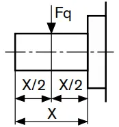 |
bei X/2 | FQ-max | lbf | 79 | 146 | 225 | 303 |
| (N) | (350) | (650) | (1000) | (1350) | ||||
| Axialkraft, max. | 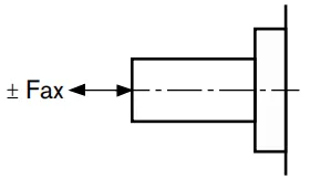 |
FAxt | lbf | 157,4 | 146 | 225 | 303 | |
| (N) | (700) | (650) | (1000) | (1350) | ||||
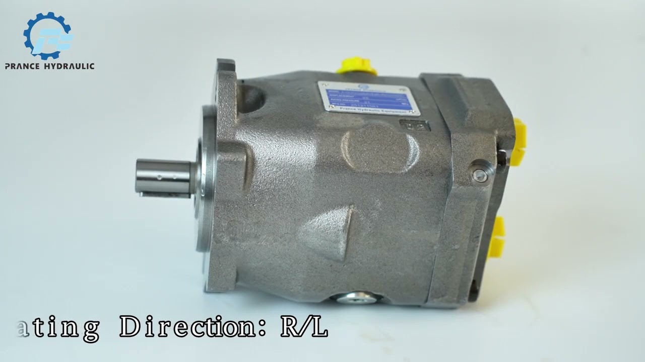
Watch A10VNO Product Video
Related Selection Resources
Request a A10VNO Quotation
Tell us your required configuration, quantity and application.
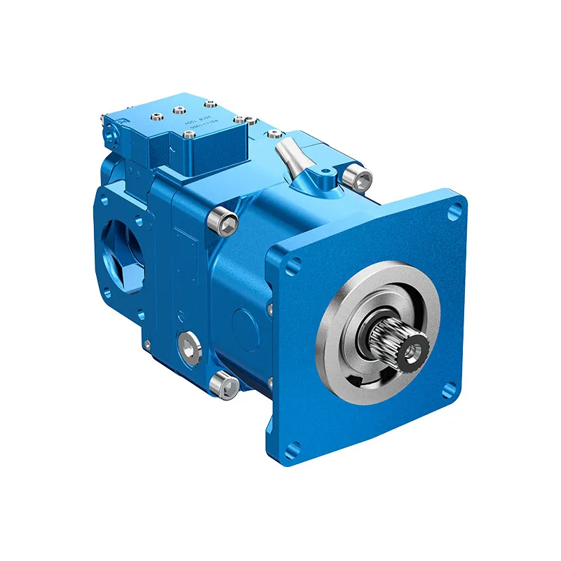
Ähnliche Produkte
Compare related hydraulic pumps and confirm the complete configuration for your application.


Bestellcode – Standardprogramm
| A10VN | ○ | DRS | / | 5x | - | V | R | C | N00 | |||
| 01 | 02 | 03 | 04 | 05 | 06 | 07 | 08 | 09 | 10 | 11 |
Axialkolbeneinheit
| 01 | Schrägscheibenbauweise, verstellbar, Nenndruck 210 bar, Spitzendruck 250 bar | A10VN |
Art der Operation
| 02 | Pumpe, offener Kreisklauf | ○ |
Größe
| 28 | 45 | 63 | 85 | |||
| 03 | ~Verdrängung VG-Max in | in3 | 1.71 | 2.75 | 3.84 | 5.19 |
| cm3 | 28 | 45 | 63 | 85 |
Steuergerät
| 04 | Druckregelung | |
| mit Stromregelung, hydraulisch, X-T geschlossen | DRS | |
Serie
| 05 | Staffel 5 | Index 2 | - | ● | ● | - | 52 |
| Index 3 | ● | - | - | ● | 53 |
Drehrichtung
| 06 | Auf das Wellenende gesehen | rechte Hand | R |
| linke Hand | L |
Robben
| 07 | FKM (Fluorkautschuk) | V |
Wellenende
| 08 | Mit SAE J744-Verzahnung | R |
Montageflansch
| 09 | SAE 2-Loch | c |
Anschlüsse für Versorgungsleitungen
| 10 | ISO 6149-1 Gewindeanschlüsse hinten, metrisch | - | ● | - | - | 40 |
| SAE-Flanschanschlüsse hinten, metrische Gewindelöcher | ● | - | ● | ● | 11 |
Technische Daten
Betriebsdruckbereich, Eingang
Absolutdruck an Anschluss S
Pabsolutes Minimum12 psi (0,8 bar)
Pabsolutes Maximum---------------------------73 psi (5 bar)
Betriebsdruckbereich, Ausgang
Druck an Anschluss B
Nenndruck PN---------------3000 psi (210 bar)
Spitzendruck PMax------------------3600 psi (250 bar)
(Drücke nach DIN 24312)
Fließrichtung
S bis B
Lecköldruck
Maximal zulässiger Gehäusedruck (Anschluss Lx):
maximal 7 psi (0,5 bar) höher als der Eingangsdruck an Anschluss S, jedoch nicht höher als 29 psi (2 bar) absolut.
PLabor max---------------------------29 psi (2 bar)
Wertestabelle (theoretische Werte, ohne Berücksichtigung von Wirkungsgraden und Toleranzen; gerundete Werte)
| Größe | 28 | 45 | 63 | 85 | |||
| Verschiebung | Vg Max | in3 (cm3) | 1.71(28) | 2.75 (45) | 3.84(63) | 5.19(85) | |
| Geschwindigkeit2) | |||||||
| max.at VG-Max | n0 Max 11) | min.-1 | 3200 | 2900 | 2700 | 2700 | |
| Fluss | |||||||
| bei n0 max | qv0 Max 11) | gpm | 23.8 | 34.6 | 45 | 60.8 | |
| (l/min) | (90) | (131) | (170) | (230) | |||
| Macht | Δp = 3000 psi (210 bar) | ||||||
| bei n0 max | P0 Max 11) | PS (kW) | 42 (31) | 62(46) | 79 (59) | 107 (80) | |
| Drehmoment | Δp = 3000 psi (210 bar) | ||||||
| bei VG-Max | TMax | lb-ft (Nm) | 69 (94) | 110 (150) | 155 (210) | 209 (284) | |
| Torsionssteifigkeit | Wellenende R | c | Pfund-Fuß pro Radian
(Nm/rad) |
10882 | 19480 | 29770 | 51029 |
| (14800) | (26500) | (40500) | (69400) | ||||
| Trägheitsmoment der Dreheinheit | JTW | Pfund-Fuß pro Radian
(kg/m²) |
0.0403 | 0.0474 | 0.0949 | 0.423 | |
| (0,001) | (0,002) | (0,004) | (0,006) | ||||
| Max. Winkelbeschleunigung.2) | α | rad/s2 | 6800 | 4900 | 3500 | 2500 | |
| Fallzahl | V | gal(L) | 0.08 (0,25) | 0.08 (0,3) | 0.13 (0,5) | 0.21 (0,8) | |
| Gewicht (mit Druckregelung) | m | lbs (kg) | 25.3 (11,5) | 31 (14) | 39.7 (18) | 48.5 (22) | |
1)selbstansaugend mit einem absolutem Druck von 15 psi (1 bar) am Einlassanschluss S
2) -Diese Werte gelten für Bedingungen zwischen den min. erforderlichen und den max. zulässigen Antriebsdrehzahlen.
Für externe Erregerquellen (z. B. Dieselmotor 2- bis 8-fache Drehzahlfrequenz, Kardanwelle 2-fache Drehzahlfrequenz).
- Das Limit gilt für eine einzelne Pumpe.
-Die Tragfähigkeit der Verbindungsteile muss berücksichtigt werden.
Vorsicht: Das Überschreiten dieser Grenzwerte kann zum Verlust der Funktionsfähigkeit, zur Verkürzung der Lebensdauer oder zur vollständigen Zerstörung der Axialkolbeneinheit führen.
Die zulässigen Werte können berechnet werden
Bestimmung der Pumpengröße
| Fluss | qv=(Vg ∙ n ∙ ηv) /231(1000) | l/min |
| Drehmoment | M=(Vg ∙ Δp) / 24(20) ∙ π ∙ ηmh | lb-ft(Nm) |
| Macht | P=(2π ∙ M ∙ n)/33000(60000)=(qv ∙ p)/[1714(600) ∙ ηt] | PS (kW) |
Vg=geometrische Verdrängung pro Umdrehung in in3 (cm3)
p = Druckdifferenz in psi (bar)
n = Antriebsdrehzahl in U/min
ηv = volumetrischer Wirkungsgrad
ηmh= mechanisch-hydraulischer Wirkungsgrad
ηt= Gesamtwirkungsgrad (ηt= ηv*ηmh)
Zulässige Radial- und Axialbelastung der Antriebswelle
| Größe | 28 | 45 | 63 | 85 | ||||
| Radiale Kraft, max. | |
bei X/2 | FQ-max | lbf | 79 | 146 | 225 | 303 |
| (N) | (350) | (650) | (1000) | (1350) | ||||
| Axialkraft, max. | |
FAxt | lbf | 157,4 | 146 | 225 | 303 | |
| (N) | (700) | (650) | (1000) | (1350) | ||||
