Wenzhou Prance Hydraulic Equipment Co., Ltd

-2.webp "A10VNO63DFR-52R(01) (2)")
-1.webp "A10VNO63DFR-52R(01) (1)")
-3.webp "A10VNO63DFR-52R(01) (3)")
-4.webp "A10VNO63DFR-52R(01) (4)")
-5.webp "A10VNO63DFR-52R(01) (5)")
-6.webp "A10VNO63DFR-52R(01) (6)")
Hydraulic Variable Displacement Piston Pump A10VNO
1.Axial piston variable pump in swashplate design forhydrostatic drives in open circuits
2.Flow is proportional to drive speed and displacement. It canbe infinitely varied by adjustment of the swashplate.
3.High power to weight ratio-small dimensions
4.Low noise level
5.Permissible continuous pressure 210 bar
6.Axial and radial loading of drive shaft possible- Pressure and flow control
Description détaillée
This is an axial piston variable pump with a swashplate design, specifically engineered for hydrostatic drive systems in open circuits, making it suitable for a wide range of industrial and mobile hydraulic applications. The pump’s output flow is directly proportional to its drive speed and displacement; by adjusting the swashplate angle precisely, the flow can be infinitely and steplessly varied, allowing flexible adaptation to the changing flow requirements of the hydraulic system during operation. It features a high power-to-weight ratio paired with small dimensions, which effectively saves installation space, reduces the overall weight of the supporting equipment, and simplifies layout in compact installation environments. Additionally, the pump operates at a low noise level, ensuring quiet and stable performance, which is ideal for noise-sensitive working sites. Its permissible continuous pressure is 210 bar, enabling reliable long-term operation under rated pressure conditions. The drive shaft supports both axial and radial loading, enhancing its adaptability to different installation configurations, and it is equipped with integrated pressure and flow control functions to achieve accurate regulation of the hydraulic system.
Sélection et DPX
Cette gamme de produits doit être choisie en fonction du circuit hydraulique approuvé. Confirmez le débit ou la cylindrée requis, la pression continue et de pointe, la vitesse d'entraînement, le type de commande, le fluide et l'interface d'installation avant la sélection finale.
Informations à inclure dans votre demande de devis
- Cylindrée ou débit requis à la vitesse de service
- Pression système continue et de pointe
- Vitesse d'entraînement, exigence de contrôle et type de circuit
- Bride de fixation, arbre, orifices, exigences en matière de fluide et de filtration
Ressources associées
Ordering code - Standard program
| A10VN | ○ | SRD | / | 5x | - | V | R | C | N00 | |||
| 01 | 02 | 03 | 04 | 05 | 06 | 07 | 08 | 09 | 10 | 11 |
Unité à pistons axiaux
| 01 | Swash plate design, variable, nominal pressure 210 bar, peak pressure 250 bar | A10VN |
Type of operation
| 02 | Pompe à circuit ouvert | ○ |
Taille
| 28 | 45 | 63 | 85 | |||
| 03 | ~Displacement VGiga in | in3 | 1.71 | 2.75 | 3.84 | 5.19 |
| cm3 | 28 | 45 | 63 | 85 |
Dispositif de commande
| 04 | Contrôle de la pression | |
| with flow control, hydraulic, X-T closed | SRD | |
Séries
| 05 | Series 5 | Index 2 | - | ● | ● | - | 52 |
| Index 3 | ● | - | - | ● | 53 |
Sens de rotation
| 06 | Viewed on shaft end | right hand | R |
| left hand | L |
Seals
| 07 | FKM(Fluor-rubber) | V |
Shaft end
| 08 | Splined to SAE J744 | R |
Bride de fixation
| 09 | SAE 2-hole | c |
Ports for service lines
| 10 | ISO 6149-1 threaded ports at rear, metric | - | ● | - | - | 40 |
| SAE flange ports at rear, metric bolt holes | ● | - | ● | ● | 11 |
Données techniques
Operating pressure range, inlet
Pression absolue à l'orifice S
Pabs min---------------------------12 psi (0,8 bar)
Pabs max---------------------------73 psi (5 bar)
Operating pressure range, outlet
Pression à l'orifice B
Pression nominale PN---------------3000 psi (210 bar)
Pression de crête Pmonx------------------3600 psi (250 bar)
(Pressures to DIN 24312)
Direction of flow
S to B
Pression de drainage du carter
Maximum permissible case drain pressure (port Lx):
maximum 7 psi (0,5 bar) higher than the inlet pressure at port S, however not higher than 29 psi (2 bar) absolute.
PLabs max---------------------------29 psi (2 bar)
Table of values (theoretical values, without considering efficiencies and tolerances; values rounded)
| Taille | 28 | 45 | 63 | 85 | |||
| Déplacement | Vg max | in3 (cm3) | 1.71(28) | 2.75 (45) | 3.84(63) | 5.19(85) | |
| Speed2) | |||||||
| max.at VGiga | n0 max 11) | min-1 | 3200 | 2900 | 2700 | 2700 | |
| Flux | |||||||
| at n0 max | qv0 max 11) | gpm | 23.8 | 34.6 | 45 | 60.8 | |
| (L/min) | (90) | (131) | (170) | (230) | |||
| Puissance | Δp= 3000 psi (210 bar) | ||||||
| at n0 max | P0 max 11) | HP(kW) | 42 (31) | 62(46) | 79 (59) | 107 (80) | |
| Torque | Δp= 3000 psi (210 bar) | ||||||
| at VGiga | Tmax | lb-ft (Nm) | 69 (94) | 110 (150) | 155 (210) | 209 (284) | |
| Torsional stiffness | shaft end R | c | lb-ft/rad
(Nm/rad) |
10882 | 19480 | 29770 | 51029 |
| (14800) | (26500) | (40500) | (69400) | ||||
| Moment of inertia rotary group | JTW | lb-ft/rad
(kgm2) |
0.0403 | 0.0474 | 0.0949 | 0.423 | |
| (0,001) | (0,002) | (0,004) | (0,006) | ||||
| Angular acceleration, max.2) | α | rad/s2 | 6800 | 4900 | 3500 | 2500 | |
| Case volume | V | gal(L) | 0.08 (0,25) | 0.08 (0,3) | 0.13 (0,5) | 0.21 (0,8) | |
| Weight (with press. control) | m | lbs (kg) | 25.3 (11,5) | 31 (14) | 39.7 (18) | 48.5 (22) | |
1)self priming with absolute pressure of 15 psi (1 bar) at inlet port S
2) -These values are valid for conditions between the min. required and the max. permissible drive speeds.
For external sources of excitation (eg. diesel engine 2-8 fold rotary frequency, cardan shaft 2-fold rotary frequency).
-The limit is valid for a single pump.
-The load carrying capacity of the connecting parts must be taken into consideration.
Caution:Exceeding these limits can lead to a loss of operability, reduction of service life or complete destruction of the axial piston unit.
The permissible values can be calculated
Determination of pump size
| Flux | qv=(Vg ∙ n ∙ ηv) /231(1000) | gpm(L/min) |
| Torque | M=(Vg ∙ Δp) / 24(20) ∙ π ∙ ηhm | lb-ft(Nm) |
| Puissance | P=(2π ∙ M ∙ n)/33000(60000)=(qv ∙ p)/[1714(600) ∙ ηt] | HP(kW) |
Vg=geometr. displacement per revolution in in3 (cm3)
p = pressure differential in psi (bar)
n= drive speed in rpm
ηv = volumetric efficiency
ηhm= mechanical-hydraulic efficiency
ηt=overall efficiency (ηt= ηv*ηhm)
Permissible radial and axial loading on drive shaft
| Taille | 28 | 45 | 63 | 85 | ||||
| Radial force, max. | 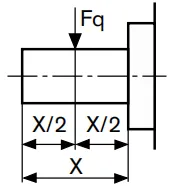 |
bei X/2 | Fq max | lbf | 79 | 146 | 225 | 303 |
| (N) | (350) | (650) | (1000) | (1350) | ||||
| Axial force, max. | 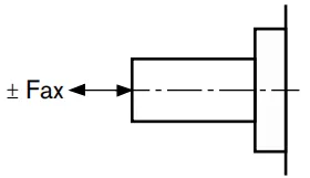 |
Fhache | lbf | 157,4 | 146 | 225 | 303 | |
| (N) | (700) | (650) | (1000) | (1350) | ||||
