Wenzhou Prance Hydraulic Equipment Co., Ltd.

Closed-Loop Hydraulic Motor Speed Control: Encoder Feedback vs Open Loop
Hydraulic motor closed-loop speed control uses measured shaft speed to correct the command sent to a valve or pump. An encoder supplies feedback; a controller compares that measurement with the requested speed and adjusts flow within defined limits. Open-loop throttling sets a command without correcting the resulting speed, so load, oil temperature, leakage, and supply changes can alter rpm. Feedback can improve regulation when the hydraulic plant has sufficient flow, pressure, and response, but an encoder cannot create torque reserve, remove a mechanical fault, or replace an independent protective stop. Choose the control architecture before choosing a sensor.
Separate a feedback loop from a closed hydraulic circuit
The word closed describes two different things in hydraulic discussions. A closed hydraulic circuit normally returns the main motor flow directly to the pump. A closed control loop returns a measurement to a controller. Either hydraulic circuit arrangement may be operated with or without external speed feedback. State explicitly which meaning appears in a specification.
A variable-displacement pump connected to a motor is not automatically a speed-regulated drive. If an operator sets pump displacement and no speed measurement corrects that setting, the speed control remains open loop. Conversely, a motor supplied through a proportional valve from an open hydraulic circuit can have a closed speed-control loop if measured shaft speed adjusts the valve command.
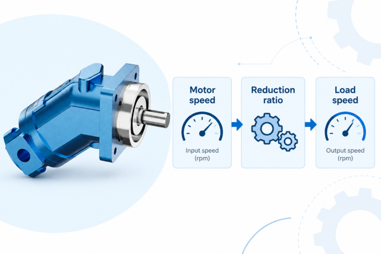
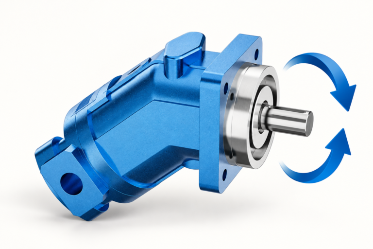
The A2FM motor used as the real product reference here is a fixed-displacement bent-axis unit. Its catalog description links speed to delivered flow and torque to pressure differential. That supports the basic plant discussion. It does not establish that an encoder, mounting adapter, controller, or particular feedback interface is included with the motor. Those are separate items to specify and verify.
Follow the information path through the system
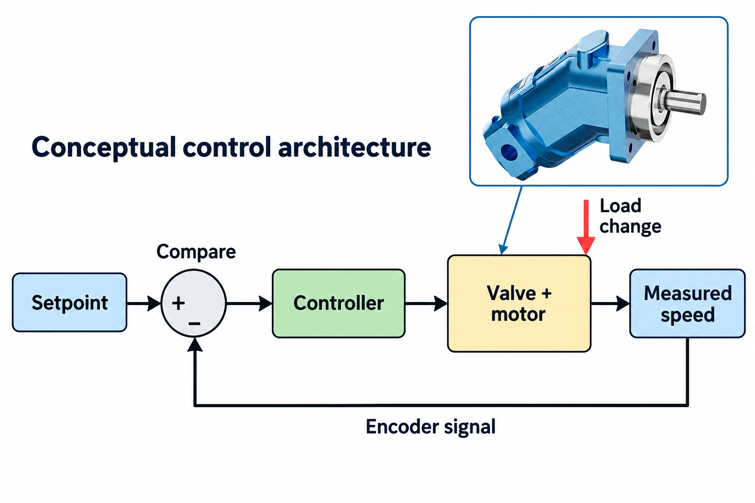
A basic speed loop has a setpoint, a measurement, a comparison, a controller, and an adjustable hydraulic element. The difference between target speed and measured speed is the control error. The controller uses that error to alter the command. The valve or pump changes motor flow, and the resulting shaft speed is measured again. The University of Illinois feedback lecture linked below provides the general disturbance-rejection foundation for this architecture.
The encoder reports movement; it does not directly regulate oil flow. Its signal must be processed into a usable speed estimate. The controller must then produce a command compatible with the selected electronics. Verify whether the hydraulic element accepts a voltage, current, fieldbus command, or another interface. Do not connect a pulse output to an analog valve input merely because both are described as control signals.
For bidirectional motion, maintain a consistent sign convention from shaft direction to measured speed and actuator command. A positive command should produce the intended direction, and the controller must interpret the feedback with the correct sign. Reversed feedback can cause a correction that increases the error. Verify direction under a controlled commissioning procedure before enabling normal closed-loop operation.
Compare open-loop and feedback control at the same duty
An open-loop command may be sufficient for a drive whose speed tolerance is broad and load changes are small. It avoids unnecessary control complexity. However, a fixed command does not guarantee fixed flow through an uncompensated valve because the pressure conditions across its metering opening can change. Motor leakage and oil viscosity can also affect the resulting shaft speed.
Feedback observes the result and can correct deviations when the plant still has operating reserve. When a conveyor load increases, for example, the loop may ask for additional flow to recover speed. If the motor cannot develop the necessary torque within its permissible differential pressure, a larger speed command will not solve the shortfall. The controller may simply reach its output limit.
The following table compares behaviors to investigate. It does not promise a particular accuracy, response time, or stability margin for an unspecified installation.
| Operating event | Open-loop behavior to assess | Feedback design question |
|---|---|---|
| Load rises at constant target speed | Rpm may shift as pressure and leakage change | Is there sufficient pressure and flow reserve to recover speed? |
| Oil warms during operation | The same command may produce a different operating point | Can the loop correct drift without saturation or instability? |
| Encoder signal disappears | A drive without feedback may continue at its existing command | What validated fault action prevents an unsafe command? |
| Very low shaft speed | Mechanical irregularity or leakage may dominate | Is speed information timely enough for the required regulation? |
| Direction changes | A command reversal does not define the complete transient | Are feedback sign, crossing zero, braking, and restart states managed? |
| Rapid load disturbance | Speed can deviate before an operator responds | Are sensing, computation, valve, and hydraulic delays acceptable? |
Evaluate both architectures against an explicit speed band, load range, settling requirement, and permitted overshoot. Without these acceptance criteria, a request for closed-loop control can produce an expensive system that still fails the machine’s actual process requirement.
Decide where to measure speed
An encoder on the motor shaft observes the motor directly. A sensor after a gearbox observes the driven output and can include effects from the transmission. Neither location is universally preferable. The measurement should represent the variable the process needs to control, while accounting for mechanical compliance, backlash, and installation constraints.
If an encoder measures the motor while the process specification concerns conveyor belt speed, the reducer ratio and any downstream slip must be considered. Good motor rpm does not prove good belt speed. If feedback comes from the load side, backlash or flexible couplings may add dynamics between command and measurement. The controller must be designed around that arrangement rather than treating the sensor location as interchangeable.
Mechanical adaptation also matters. Confirm shaft access, guarding, alignment, permitted shaft loads, environmental protection, cable routing, and service access. Do not modify a motor shaft or housing without supplier approval. An attractive reference illustration of an encoder beside a motor is not evidence that a physical mounting interface exists. Require the adapter drawing and installation responsibility in the quotation.
Distinguish resolution from usable control response
Encoder resolution describes position information per revolution. Speed is calculated from that information over time. Increasing resolution can improve the available information, but it does not by itself guarantee better regulation. The counter capability, measurement method, noise handling, update interval, and hydraulic response all contribute to what the controller actually receives.
At low speed, a simple fixed-window count may contain few edges and produce a coarse estimate. A longer window smooths that estimate but delays the measurement. A period-based method uses elapsed time between events and has its own behavior when movement stops. Choose the speed-estimation method for the required operating range and review the controller documentation. This article addresses architecture; the separate speed-measurement guide covers instrument and pulse-reading choices.
Keep units explicit throughout the signal chain. Rpm at the motor, rpm after a reducer, and percent of command are different quantities. Verify scaling with an independent safe measurement before tuning. A controller configured for the wrong ratio or pulse convention can display a convincing but incorrect speed, causing every subsequent tuning decision to be based on a false error.
Respect the limits of the hydraulic plant
For a fixed-displacement motor, more delivered flow generally means more speed, while available differential pressure determines the torque that can be developed within the selected operating limits. The speed loop therefore works through a hydraulic system that has finite capacity. Review simultaneous flow and pressure availability, return pressure, fluid temperature, and the selected motor’s operating envelope.
A valve at maximum command cannot open further to correct a speed deficit. A pressure-limited drive cannot accelerate an excessive load merely because the controller accumulates error. Controller saturation and integral windup require deliberate handling, especially during startup, a jam, or a long external stop. Ask how the command and internal controller state behave when normal regulation becomes impossible.
Speed feedback also does not eliminate pressure transients, cavitation risk, overrunning loads, or the need for suitable braking and makeup arrangements. Fast correction can interact with hose compliance, load inertia, and valve dynamics. Tune the complete machine under an approved procedure. Avoid copying gain settings from a different motor size or assuming that a faster electrical update makes the mechanical response safe.
Commission the loop in controlled stages
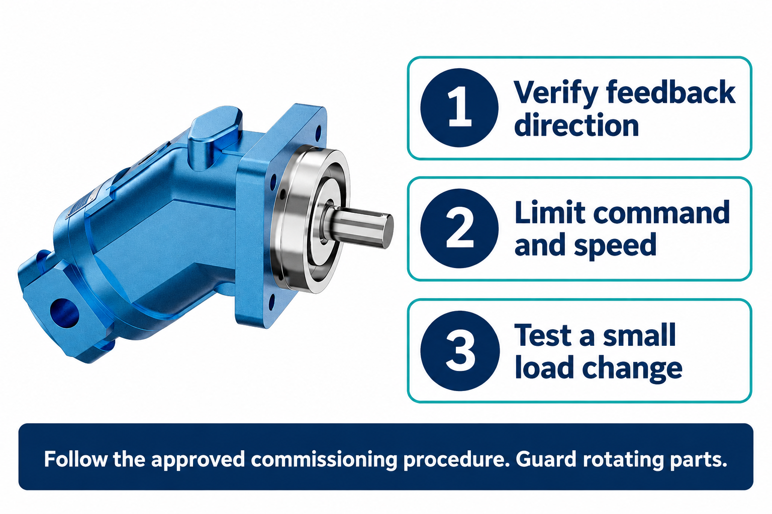
First establish a safe machine state, guarded rotating parts, and verified isolation arrangements for installation work. Confirm command limits, pressure protection, maximum speed, direction, and the intended fault responses before enabling regulation. A speed controller is a process function; any required protective function must be assessed separately and must not rely casually on the same unverified signal.
Next verify the feedback independently. Observe whether the indicated speed changes in the correct direction and scale during the approved low-energy test. Check zero-speed behavior, cable faults, and signal plausibility using the manufacturer’s procedure. Ensure that disconnecting feedback does not silently cause a full command in an attempt to correct an apparent stopped shaft.
Only then test regulation with bounded commands and small, controlled load changes. Record target speed, measured speed, actual actuator command, relevant pressures, oil temperature, and timestamps. Compare repeated runs rather than a single attractive trace. If oscillation occurs, investigate mechanical and hydraulic causes along with tuning; a noisy speed estimate, trapped air, backlash, or insufficient pressure margin can resemble a controller problem.
Specify performance and responsibility in the RFQ
State the required motor and load speed ranges, direction, load torque profile, permissible speed error, overshoot, and settling behavior. Include startup, reversal, low-speed dwell, and fault conditions. Describe the available hydraulic supply and the chosen valve or pump control interface. Specify which shaft is measured and who supplies the encoder mounting and guarding.
Ask the integrator to define feedback scaling, update method, command limits, saturation handling, loss-of-signal behavior, and acceptance tests. Require model-specific documentation for electrical connections and operating limits. A product family name is insufficient for pin assignments or controller settings. Commissioning records should identify the final configuration so a replacement motor, encoder, or valve does not become an unreviewed change to the control loop.
For purchasing, separate the bare motor from the complete regulated drive. The quotation should state whether it includes only the motor, an encoder-ready mechanical arrangement, sensing electronics, valve or pump control, programming, and machine acceptance. This prevents the phrase encoder feedback from being mistaken for a proven speed-control package.
Preguntas frecuentes
Is a closed hydraulic circuit the same as closed-loop speed control?
No. A closed hydraulic circuit describes the main oil-flow path. Closed-loop speed control describes the feedback information path. Specify both separately because either hydraulic circuit arrangement can use external speed feedback.
Can an encoder hold speed when the motor lacks torque?
No. The encoder measures movement. The drive still needs sufficient pressure, flow, motor capacity, and control range. If the actuator command saturates, the controller cannot correct the deficit by requesting an unavailable operating point.
Should feedback be measured at the motor or the load?
Measure the variable relevant to the process and account for the transmission between that point and the motor. Motor feedback may miss downstream slip, while load-side feedback can include backlash and compliance that affect tuning.
Does a higher-resolution encoder always improve regulation?
No. Resolution is only one part of the measurement chain. Counter capability, estimation interval, noise, filtering, latency, valve behavior, and hydraulic dynamics determine the usable information and response.
Does the A2FM reference product include encoder control?
The product reference establishes a fixed-displacement bent-axis motor. Do not infer an encoder, adapter, controller, or complete regulated-drive package from that description. Confirm every supplied component, interface, and acceptance responsibility in the quotation.
Recursos de producto y ingeniería relacionados
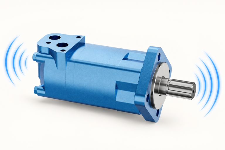
The Fixed Displacement Motor A2FM catalog exterior is used as the real product reference in these explanatory images. It does not establish the approved service method, optional construction, or operating limits for an individual order. Confirm the complete code and its documentation. Related resources: Motor de desplazamiento fijo A2FM, Gamma de motores hidráulicos, Medición de la velocidad del motor hidráulico: tacómetros, pulsaciones y registros de pruebas, Principio de funcionamiento del motor de pistón radial: Torque a baja velocidad.
Sources and limits of this guide
University references support the stated physical and control principles; the NIOSH source supports hazardous-energy precautions. Calculations are explicitly hypothetical. No linked source supplies ratings, wiring, approval, or a validated installation for the illustrated Prance product.
- University of Illinois ECE 486: feedback and disturbance rejection
- NPTEL: Industrial Oil Hydraulics and Pneumatics, motor and fluid-power principles
- NIOSH: prevención de lesiones por energía peligrosa
University lesson: operating principles
NPTEL-NOC IITM presents 6.3 – Hydraulic Motors. The lesson supports the motor flow, torque, and shaft behavior that form the hydraulic plant; external encoder control is explained separately in the article used in this discussion; it is not a model-specific performance or installation approval.