Wenzhou Prance Hydraulic Equipment Co., Ltd.


A10VO Series 53 Variable Displacement Piston Pump
The A10VO Series 53 pump provides variable displacement through a swashplate rotary group for open-circuit systems. Its series number and control suffix are important: a similar A10VO pump body from another series does not establish the same interfaces or control response.
- Open-circuit swashplate pump
- Series 53 model identification
- Electro-hydraulic pressure control
- Power-control option
PRANCE HYDRAULIC · PRODUCT SERIES
A10VO Series 53 Variable Displacement Piston Pump
Axial piston; swashplate variable displacement · Open circuit
The A10VO Series 53 pump provides variable displacement through a swashplate rotary group for open-circuit systems. Its series number and control suffix are important: a similar A10VO pump body from another series does not establish the same interfaces or control response.
Model
✓
Request a QuotationVer Datos Técnicos y Ficha TécnicaA10VO Series 53Axial piston; swashplate variable displacement
Confirm the complete model and approved specification with Prance Hydraulic. Product-series references alone do not establish interchangeability.
Configuration review · Technical documentation · Product selection
Detalles del producto
- Open-circuit swashplate pump
- Series 53 model identification
- Electro-hydraulic pressure control
- Power-control option
CATEGORIES: Bomba de pistón, Bomba de desplazamiento variable
A10VO Series 53 Features & Application
Open-circuit swashplate pump
Review normal running, startup and reversal where applicable. The pressure and flow requirements can differ between operating states.
Series 53 model identification
Include the series and all order-code suffixes in the enquiry. A common nominal size does not establish compatibility.
Electro-hydraulic pressure control
Match the complete control option and its command requirements to the existing controller. Similar housings can use different control arrangements.
Power-control option
Match the complete control option and its command requirements to the existing controller. Similar housings can use different control arrangements.
A10VO Series 53 Specifications
| Series / model | A10VO Series 53 |
|---|---|
| Product type | A10VO Series 53 Variable Displacement Piston Pump |
| Diseño | Axial piston; swashplate variable displacement |
| Circuit / selection | Open circuit |
| Series | 53 |
| Published nominal-size table | 10, 18, 28, 45, 60, 63, 72, 85 and 100; confirm availability by series and control |
A10VO Series 53 Selection & Configuration
The A10VO Series 53 pump provides variable displacement through a swashplate rotary group for open-circuit systems. Its series number and control suffix are important: a similar A10VO pump body from another series does not establish the same interfaces or control response.
For electrical pressure or power control, provide the command signal, supply requirements and required response together with the flow-pressure duty. Keep the Series 53 order code attached to the approved drawing when comparing Series 31, 32 or 52 alternatives.

cURL Too many subrequests by single Worker invocation. To configure this limit, refer to https://developers.cloudflare.com/workers/wrangler/configuration/#limits.
cURL Too many subrequests by single Worker invocation. To configure this limit, refer to https://developers.cloudflare.com/workers/wrangler/configuration/#limits.
Hydraulic pumps · Hydraulic motors · Hydraulic valves
Send the A17FO Series 10 nameplate, operating requirements and installation drawing for a configuration review before quoting.
- Model review — send the full model code or an existing nameplate photograph.
- Interface matching — confirm shaft, mounting flange, rotation and ports.
- Operating conditions — provide flow, pressure, speed, fluid and duty cycle.
- Documentation — request the relevant product data and drawings for your review.

A10VO Series 53 Buying Guide
Use this sequence to prepare the A10VO Series 53 configuration for review and quotation.
- Define required flow at the actual drive speed and continuous pressure.
- Identify peak pressure, duration and the work cycle.
- Confirm the selected displacement control and any auxiliary-drive requirement.
- Match rotation viewed from the shaft end, shaft, flange and ports.
- Review inlet conditions, drain routing and the installation envelope.
- Confirm fluid, viscosity, temperature, filtration and seals.
- Approve the complete model, control, drawing, quantity and delivery terms.

Selection, Documentation & Project Support

Selection Support
Learn more →Share your hydraulic circuit, operating point and installation requirements for a configuration discussion.
Flow · Pressure · Speed · Interfaces

Technical Resources
Learn more →Review product documentation, model codes and technical data before finalizing the specification.
Datasheets · Model codes · Drawings

Project Inquiries
Learn more →Send your required model, quantity, application and project requirements to discuss your inquiry.
Product inquiries · Configuration review
Configuration, Quantity & Delivery
Confirm the complete A17FO Series 10 code, approved drawing and operating limits. Availability, quantity, documentation and delivery date are confirmed in the quotation.
Discuss Your A10VO Series 53 Application
Send the full model code, operating duty, installation details and quantity.
Request a A10VO Series 53 QuotationA10VO Series 53 Questions Before Ordering
What type of product is the A10VO Series 53?
A10VO Series 53 Variable Displacement Piston Pump. Design: Axial piston; swashplate variable displacement. Open circuit. Confirm the complete order code for the offered version.
Can a similar pump replace the A10VO Series 53?
cURL Too many subrequests by single Worker invocation. To configure this limit, refer to https://developers.cloudflare.com/workers/wrangler/configuration/#limits.
cURL Too many subrequests by single Worker invocation. To configure this limit, refer to https://developers.cloudflare.com/workers/wrangler/configuration/#limits
Define required flow at the actual drive speed and continuous pressure. Identify peak pressure, duration and the work cycle. Attach the nameplate, complete order code, installation drawing and required quantity.
A10VO Series 53 Technical Data & Documents
View A10VO Series 53 catalog data and operating conditions
cURL Too many subrequests by single Worker invocation. To configure this limit, refer to https://developers.cloudflare.com/workers/wrangler/configuration/#limits.
Datos técnicos
| Tamaño | NG | 10 | 18 | 28 | 45 | 60 | 63 | 72 | 85 | 100 | ||
| Desplazamiento geométrico por revolución | Vg máx | cm3 | 10.5 | 18 | 28 | 45 | 60 | 63 | 72 | 85 | 100 | |
| Rotational speed maximum1) | en VG máximo | nNombre | rpm | 3600 | 3300 | 3000 | 26004) | 2700 | 2600 | 2600 | 2500 | 2300 |
| en Vg <Vg máx 2) | nadm. máx. | rpm | 4320 | 3960 | 3600 | 3120 | 3140 | 3140 | 3140 | 3000 | 2500 | |
| Flujo | enNombre y VG máximo | qv | l/min | 37 | 59 | 84 | 117 | 162 | 163 | 187 | 212 | 230 |
| enE = 1500 rpm | qvE | l/min | 15 | 27 | 42 | 68 | 90 | 95 | 108 | 128 | 150 | |
| Poder | Con NNombre, VG máximo y Δp = 250 bar | P | kW | 16 | 25 | 35 | 49 | 65 | 68 | 77 | 89 | 96 |
| enE= 1500 rpm | PE | kW | 7 | 11 | 18 | 28 | 37 | 39 | 45 | 53 | 62 | |
| Par de torsión | en VG máximo y Δp = 250 bar | M | Nm | 42 | 71 | 111 | 179 | 238 | 250 | 286 | 338 | 398 |
| en VG máximo y Δp = 100 bar | M | Nm | 17 | 29 | 45 | 72 | 95 | 100 | 114 | 135 | 159 | |
| Rigidez torsional del eje de transmisión | S | c | Nm/rad | 9200 | 11000 | 22300 | 37500 | 65500 | 65500 | 65500 | 143000 | 143000 |
| R | c | Nm/rad | – | 14800 | 26300 | 41000 | 69400 | 69400 | 69400 | 152900 | 152900 | |
| U | c | Nm/rad | 6800 | 8000 | 16700 | 30000 | 49200 | 49200 | 49200 | 102900 | 102900 | |
| W | c | Nm/rad | – | – | 19900 | 34400 | 54000 | 54000 | 54000 | 117900 | 117900 | |
| P | c | Nm/rad | 10700 | – | – | – | – | – | – | – | – | |
| Momento de inercia del grupo rotativo | JTW | Kgm2 | 0.0006 | 0.0009 | 0.0017 | 0.003 | 0.0056 | 0.0056 | 0.0056 | 0.012 | 0.012 | |
| Aceleración angular máxima3) | α | rad/s2 | 8000 | 6800 | 5500 | 4000 | 3300 | 3300 | 3300 | 2700 | 2700 | |
| Volumen de casos | V | L | 0.2 | 0.25 | 0.3 | 0.5 | 0.8 | 0.8 | 0.8 | 1 | 1 | |
| Weight without through drive (approx.) Weight with through drive (approx.) | m | kg | 8 | 11.5 | 15 | 18 | 22 | 22 | 22 | 36 | 36 | |
| – | 13 | 18 | 24 | 28 | 28 | 28 | 45 | 45 | ||||
Determinación de las características de funcionamiento
Fuerzas radiales y axiales admisibles en el eje de transmisión
| Tamaño | NG | 10 | 18 | 28 | 45 | 60/63 | 72 | 85 | 100 | ||
| Fuerza radial máxima en a/2 |  fuerza radial |
Fcuántos máximos | N | 250 | 350 | 1200 | 1500 | 1700 | 1500 | 2000 | 2000 |
| Fuerza axial máxima | 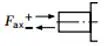 fuerza axial |
±Fax max | N | 400 | 700 | 1000 | 1500 | 2000 | 1500 | 3000 | 3000 |
Par de entrada admisible y par a través del eje
| Tamaño | 10 | 18 | 28 | 45 | 60/63 | 72 | 85 | 100 | |||
| Par de entrada máximo en el eje de transmisión2) | |||||||||||
| S | ME máx | Nm | 126 | 124 | 198 | 319 | 630 | 630 | 1157 | 1157 | |
| ∅ | en | 3/4 | 3/4 | 7/8 | 1 | 1 1/4 | 1 1/4 | 1 1/2 | 1 1/2 | ||
| R | ME máx | Nm | – | 160 | 250 | 400 | 650 | 650 | 1215 | 1215 | |
| ∅ | en | – | 3/4 | 7/8 | 1 | 1 1/4 | 1 1/4 | 1 1/2 | 1 1/2 | ||
| U | ME máx | Nm | 60 | 59 | 105 | 188 | 306 | 306 | 628 | 628 | |
| ∅ | en | 5/8 | 5/8 | 3/4 | 7/8 | 1 | 1 | 1 1/4 | 1 1/4 | ||
| W | ME máx | Nm | – | – | 140 | 220 | 396 | 383 | 650 | 650 | |
| ∅ | en | – | – | 3/4 | 7/8 | 1 | 1 | 1 1/4 | 1 1/4 | ||
| P | ME máx | Nm | 90 | – | – | – | – | – | – | – | |
| ∅ | mm | 18 | – | – | – | – | – | – | – | ||
| Par máximo de transmisión continua | |||||||||||
| S | MD máx | Nm | – | 108 | 160 | 319 | 484 | 484 | 698 | 698 | |
| R | MD máx | Nm | – | 120 | 176 | 365 | 484 | 484 | 698 | – | |
| U | MD máx | Nm | – | 59 | 105 | 188 | 306 | 306 | 628 | 628 | |
| W | MD máx | Nm | – | – | 140 | 220 | 396 | 383 | 650 | 650 | |
Distribución de pares
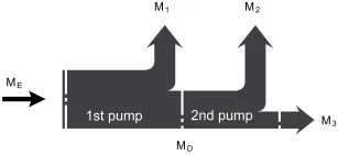
| Par de entrada | ME=M1+M2+M3 |
| ME < ME máx | |
| Par de apriete a través del eje | MD=M2+M3 |
| MD < MD máx |
Watch A10VO Series 53 Product Video
Related Selection Resources
Request a A10VO Series 53 Quotation
Tell us your required configuration, quantity and application.
Productos relacionados
Compare related hydraulic pumps and confirm the complete configuration for your application.
Datos técnicos
| Tamaño | NG | 10 | 18 | 28 | 45 | 60 | 63 | 72 | 85 | 100 | ||
| Desplazamiento geométrico por revolución | Vg máx | cm3 | 10.5 | 18 | 28 | 45 | 60 | 63 | 72 | 85 | 100 | |
| Velocidad de giro
máximo1) |
en VG máximo | nNombre | rpm | 3600 | 3300 | 3000 | 26004) | 2700 | 2600 | 2600 | 2500 | 2300 |
| en Vg <Vg máx 2) | nadm. máx. | rpm | 4320 | 3960 | 3600 | 3120 | 3140 | 3140 | 3140 | 3000 | 2500 | |
| Flujo | enNombre y VG máximo | qv | l/min | 37 | 59 | 84 | 117 | 162 | 163 | 187 | 212 | 230 |
| enE = 1500 rpm | qvE | l/min | 15 | 27 | 42 | 68 | 90 | 95 | 108 | 128 | 150 | |
| Poder | Con NNombre, VG máximo
y Δp = 250 bar |
P | kW | 16 | 25 | 35 | 49 | 65 | 68 | 77 | 89 | 96 |
| enE= 1500 rpm | PE | kW | 7 | 11 | 18 | 28 | 37 | 39 | 45 | 53 | 62 | |
| Par de torsión | en VG máximo
y Δp = 250 bar |
M | Nm | 42 | 71 | 111 | 179 | 238 | 250 | 286 | 338 | 398 |
| en VG máximo
y Δp = 100 bar |
M | Nm | 17 | 29 | 45 | 72 | 95 | 100 | 114 | 135 | 159 | |
| Rigidez torsional del eje de transmisión | S | c | Nm/rad | 9200 | 11000 | 22300 | 37500 | 65500 | 65500 | 65500 | 143000 | 143000 |
| R | c | Nm/rad | - | 14800 | 26300 | 41000 | 69400 | 69400 | 69400 | 152900 | 152900 | |
| U | c | Nm/rad | 6800 | 8000 | 16700 | 30000 | 49200 | 49200 | 49200 | 102900 | 102900 | |
| W | c | Nm/rad | - | - | 19900 | 34400 | 54000 | 54000 | 54000 | 117900 | 117900 | |
| P | c | Nm/rad | 10700 | - | - | - | - | - | - | - | - | |
| Momento de inercia del grupo rotativo | JTW | Kgm2 | 0.0006 | 0.0009 | 0.0017 | 0.003 | 0.0056 | 0.0056 | 0.0056 | 0.012 | 0.012 | |
| Aceleración angular máxima3) | α | rad/s2 | 8000 | 6800 | 5500 | 4000 | 3300 | 3300 | 3300 | 2700 | 2700 | |
| Volumen de casos | V | L | 0.2 | 0.25 | 0.3 | 0.5 | 0.8 | 0.8 | 0.8 | 1 | 1 | |
| Peso sin transmisión pasante (aprox.)
Peso con propulsión por popa (aprox.) |
m | kg | 8 | 11.5 | 15 | 18 | 22 | 22 | 22 | 36 | 36 | |
| - | 13 | 18 | 24 | 28 | 28 | 28 | 45 | 45 | ||||
Determinación de las características de funcionamiento
| Flujo | qv=(Vg ∙ n ∙ ηv) / 1000 | l/min |
| Par de torsión | M=(Vg ∙ Δp) /(20 ∙ π ∙ ηhm) | Nm |
| Poder | P=(2π ∙ M ∙ n)/60000=(qv ∙ Δp)/(600 ∙ ηt) | kW |
Clave
Vg Cilindrada por revolución en [cm3]
Δp Presión diferencial [bar]
n Velocidad de giro [rpm]
ηv Eficiencia volumétrica
ηhm Rendimiento hidráulico-mecánico
ηt Eficiencia total (ηt= ηv*ηhm)
1) Los valores son aplicables:
- A una presión absoluta pabdominales = 1 bar en el puerto de aspiración S
- para el rango de viscosidad óptimo desde Velegir = 36 a 16 mm2/s
- con aceite hidráulico a base de aceites minerales
2)Ver diagrama en la página 9 a un aumento de velocidad de hasta nmáx adm.
3)Los datos son válidos para valores comprendidos entre la velocidad de giro mínima requerida y la máxima admisible. Se aplica a estímulos externos (p. ej., motor diésel de 2 a 8 veces la frecuencia de giro, árbol cardán dos veces la frecuencia de giro). El valor límite solo es válido para una sola bomba. Se debe tener en cuenta la capacidad de carga de las piezas de conexión.
Fuerzas radiales y axiales admisibles en el eje de transmisión
| Tamaño | NG | 10 | 18 | 28 | 45 | 60/63 | 72 | 85 | 100 | ||
| Fuerza radial máxima en a/2 |
fuerza radial |
Fcuántos máximos | N | 250 | 350 | 1200 | 1500 | 1700 | 1500 | 2000 | 2000 |
| Fuerza axial máxima |
fuerza axial |
±Fax max | N | 400 | 700 | 1000 | 1500 | 2000 | 1500 | 3000 | 3000 |
Par de entrada admisible y par a través del eje
| Tamaño | 10 | 18 | 28 | 45 | 60/63 | 72 | 85 | 100 | |||
| Par en VG máximo y Δp = 250 bar1) | Mmáx | Nm | 42 | 71 | 111 | 179 | 250 | 321 | 338 | 398 | |
| Par de entrada máximo en el eje de transmisión2) | |||||||||||
| S | ME máx | Nm | 126 | 124 | 198 | 319 | 630 | 630 | 1157 | 1157 | |
| ∅ | en | 3/4 | 3/4 | 7/8 | 1 | 1 1/4 | 1 1/4 | 1 1/2 | 1 1/2 | ||
| R | ME máx | Nm | - | 160 | 250 | 400 | 650 | 650 | 1215 | 1215 | |
| ∅ | en | - | 3/4 | 7/8 | 1 | 1 1/4 | 1 1/4 | 1 1/2 | 1 1/2 | ||
| U | ME máx | Nm | 60 | 59 | 105 | 188 | 306 | 306 | 628 | 628 | |
| ∅ | en | 5/8 | 5/8 | 3/4 | 7/8 | 1 | 1 | 1 1/4 | 1 1/4 | ||
| W | ME máx | Nm | - | - | 140 | 220 | 396 | 383 | 650 | 650 | |
| ∅ | en | - | - | 3/4 | 7/8 | 1 | 1 | 1 1/4 | 1 1/4 | ||
| P | ME máx | Nm | 90 | - | - | - | - | - | - | - | |
| ∅ | mm | 18 | - | - | - | - | - | - | - | ||
| Par máximo de transmisión continua | |||||||||||
| S | MD máx | Nm | - | 108 | 160 | 319 | 484 | 484 | 698 | 698 | |
| R | MD máx | Nm | - | 120 | 176 | 365 | 484 | 484 | 698 | - | |
| U | MD máx | Nm | - | 59 | 105 | 188 | 306 | 306 | 628 | 628 | |
| W | MD máx | Nm | - | - | 140 | 220 | 396 | 383 | 650 | 650 | |
Distribución de pares
| Par en la 1.ª bomba | M1 |
| Par en la segunda bomba | M2 |
| Par en la tercera bomba | M3 |
| Par de entrada | ME=M1+M2+M3 |
| ME < ME máx | |
| Par de apriete a través del eje | MD=M2+M3 |
| MD < MD máx |
1)Eficiencia no considerada
2) Para árboles de transmisión sin fuerza radial
