Wenzhou Prance Hydraulic Equipment Co., Ltd


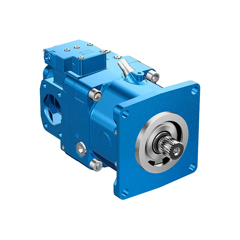
A10VO Series 53 Variable Displacement Piston Pump
The A10VO Series 53 pump provides variable displacement through a swashplate rotary group for open-circuit systems. Its series number and control suffix are important: a similar A10VO pump body from another series does not establish the same interfaces or control response.
- Open-circuit swashplate pump
- Series 53 model identification
- Electro-hydraulic pressure control
- Power-control option
PRANCE HYDRAULIC · PRODUCT SERIES
A10VO Series 53 Variable Displacement Piston Pump
Axial piston; swashplate variable displacement · Open circuit
The A10VO Series 53 pump provides variable displacement through a swashplate rotary group for open-circuit systems. Its series number and control suffix are important: a similar A10VO pump body from another series does not establish the same interfaces or control response.
Modèle
✓
Demander un devisVoir les données techniques et la fiche techniqueA10VO Series 53Axial piston; swashplate variable displacement
Confirm the complete model and approved specification with Prance Hydraulic. Product-series references alone do not establish interchangeability.
Étude de configuration · Documentation technique · Sélection de produits
Détails du produit
- Open-circuit swashplate pump
- Series 53 model identification
- Electro-hydraulic pressure control
- Power-control option
CATÉGORIES : Pompe à piston, Pompe à cylindrée variable
A10VO Series 53 Features & Application
Open-circuit swashplate pump
Review normal running, startup and reversal where applicable. The pressure and flow requirements can differ between operating states.
Series 53 model identification
Include the series and all order-code suffixes in the enquiry. A common nominal size does not establish compatibility.
Electro-hydraulic pressure control
Match the complete control option and its command requirements to the existing controller. Similar housings can use different control arrangements.
Power-control option
Match the complete control option and its command requirements to the existing controller. Similar housings can use different control arrangements.
A10VO Series 53 Specifications
| Series / model | A10VO Series 53 |
|---|---|
| Product type | A10VO Series 53 Variable Displacement Piston Pump |
| Conception | Axial piston; swashplate variable displacement |
| Circuit / selection | Circuit ouvert |
| Séries | 53 |
| Published nominal-size table | 10, 18, 28, 45, 60, 63, 72, 85 and 100; confirm availability by series and control |
A10VO Series 53 Selection & Configuration
The A10VO Series 53 pump provides variable displacement through a swashplate rotary group for open-circuit systems. Its series number and control suffix are important: a similar A10VO pump body from another series does not establish the same interfaces or control response.
For electrical pressure or power control, provide the command signal, supply requirements and required response together with the flow-pressure duty. Keep the Series 53 order code attached to the approved drawing when comparing Series 31, 32 or 52 alternatives.

Your Application.
The Right Configuration.
Hydraulic pumps · Hydraulic motors · Hydraulic valves
Send the A17FO Series 10 nameplate, operating requirements and installation drawing for a configuration review before quoting.
- Model review — send the full model code or an existing nameplate photograph.
- Interface matching — confirm shaft, mounting flange, rotation and ports.
- Operating conditions — provide flow, pressure, speed, fluid and duty cycle.
- Documentation — request the relevant product data and drawings for your review.

A10VO Series 53 Buying Guide
Use this sequence to prepare the A10VO Series 53 configuration for review and quotation.
- Define required flow at the actual drive speed and continuous pressure.
- Identify peak pressure, duration and the work cycle.
- Confirm the selected displacement control and any auxiliary-drive requirement.
- Match rotation viewed from the shaft end, shaft, flange and ports.
- Review inlet conditions, drain routing and the installation envelope.
- Confirm fluid, viscosity, temperature, filtration and seals.
- Approve the complete model, control, drawing, quantity and delivery terms.

Selection, Documentation & Project Support

Selection Support
Learn more →Share your hydraulic circuit, operating point and installation requirements for a configuration discussion.
Flow · Pressure · Speed · Interfaces

Technical Resources
Learn more →Review product documentation, model codes and technical data before finalizing the specification.
Datasheets · Model codes · Drawings

cURL Too many subrequests by single Worker invocation. To configure this limit, refer to https://developers.cloudflare.com/workers/wrangler/configuration/#limits
Learn more →cURL Too many subrequests by single Worker invocation. To configure this limit, refer to https://developers.cloudflare.com/workers/wrangler/configuration/#limits.
cURL Too many subrequests by single Worker invocation. To configure this limit, refer to https://developers.cloudflare.com/workers/wrangler/configuration/#limits
Configuration, Quantity & Delivery
Confirm the complete A17FO Series 10 code, approved drawing and operating limits. Availability, quantity, documentation and delivery date are confirmed in the quotation.
Discuss Your A10VO Series 53 Application
Send the full model code, operating duty, installation details and quantity.
Request a A10VO Series 53 QuotationA10VO Series 53 Questions Before Ordering
What type of product is the A10VO Series 53?
A10VO Series 53 Variable Displacement Piston Pump. Design: Axial piston; swashplate variable displacement. Open circuit. Confirm the complete order code for the offered version.
Can a similar pump replace the A10VO Series 53?
cURL Too many subrequests by single Worker invocation. To configure this limit, refer to https://developers.cloudflare.com/workers/wrangler/configuration/#limits.
cURL Too many subrequests by single Worker invocation. To configure this limit, refer to https://developers.cloudflare.com/workers/wrangler/configuration/#limits
Define required flow at the actual drive speed and continuous pressure. Identify peak pressure, duration and the work cycle. Attach the nameplate, complete order code, installation drawing and required quantity.
A10VO Series 53 Technical Data & Documents
View A10VO Series 53 catalog data and operating conditions
cURL Too many subrequests by single Worker invocation. To configure this limit, refer to https://developers.cloudflare.com/workers/wrangler/configuration/#limits.
Données techniques
| Taille | NG | 10 | 18 | 28 | 45 | 60 | 63 | 72 | 85 | 100 | ||
| Cylindrée géométrique par tour | Vg max | cm3 | 10.5 | 18 | 28 | 45 | 60 | 63 | 72 | 85 | 100 | |
| Rotational speed maximum1) | à VGiga | nnom | tours par minute | 3600 | 3300 | 3000 | 26004) | 2700 | 2600 | 2600 | 2500 | 2300 |
| à Vg <Vg max 2) | nadm. max. | tours par minute | 4320 | 3960 | 3600 | 3120 | 3140 | 3140 | 3140 | 3000 | 2500 | |
| Flux | à nnom et VGiga | qv | L/min | 37 | 59 | 84 | 117 | 162 | 163 | 187 | 212 | 230 |
| à nE = 1500 tr/min | qvE | L/min | 15 | 27 | 42 | 68 | 90 | 95 | 108 | 128 | 150 | |
| Puissance | Avec Nnom, VGiga et Δp = 250 bar | P | kW | 16 | 25 | 35 | 49 | 65 | 68 | 77 | 89 | 96 |
| à nE= 1500 tr/min | PE | kW | 7 | 11 | 18 | 28 | 37 | 39 | 45 | 53 | 62 | |
| Couple | à VGiga et Δp = 250 bar | M | Rien | 42 | 71 | 111 | 179 | 238 | 250 | 286 | 338 | 398 |
| à VGiga et Δp = 100 bar | M | Rien | 17 | 29 | 45 | 72 | 95 | 100 | 114 | 135 | 159 | |
| Rigidité de rotation arbre d'entraînement | S | c | Nm/rad | 9200 | 11000 | 22300 | 37500 | 65500 | 65500 | 65500 | 143000 | 143000 |
| R | c | Nm/rad | – | 14800 | 26300 | 41000 | 69400 | 69400 | 69400 | 152900 | 152900 | |
| U | c | Nm/rad | 6800 | 8000 | 16700 | 30000 | 49200 | 49200 | 49200 | 102900 | 102900 | |
| W | c | Nm/rad | – | – | 19900 | 34400 | 54000 | 54000 | 54000 | 117900 | 117900 | |
| P | c | Nm/rad | 10700 | – | – | – | – | – | – | – | – | |
| Moment d'inertie du groupe tournant | JTW | Kgm2 | 0.0006 | 0.0009 | 0.0017 | 0.003 | 0.0056 | 0.0056 | 0.0056 | 0.012 | 0.012 | |
| Accélération angulaire maximale3) | α | rad/s2 | 8000 | 6800 | 5500 | 4000 | 3300 | 3300 | 3300 | 2700 | 2700 | |
| Volume du boîtier | V | L | 0.2 | 0.25 | 0.3 | 0.5 | 0.8 | 0.8 | 0.8 | 1 | 1 | |
| Weight without through drive (approx.) Weight with through drive (approx.) | m | kg | 8 | 11.5 | 15 | 18 | 22 | 22 | 22 | 36 | 36 | |
| – | 13 | 18 | 24 | 28 | 28 | 28 | 45 | 45 | ||||
Définir les caractéristiques de fonctionnement
Forces radiales et axiales admissibles sur l'arbre d'entraînement
| Taille | NG | 10 | 18 | 28 | 45 | 60/63 | 72 | 85 | 100 | ||
| Force radiale maximale à a/2 |  force radiale |
Fq max | N | 250 | 350 | 1200 | 1500 | 1700 | 1500 | 2000 | 2000 |
| Force axiale maximale | 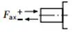 force axiale |
±Fax max | N | 400 | 700 | 1000 | 1500 | 2000 | 1500 | 3000 | 3000 |
couples d'entrée et de transmission admissibles
| Taille | 10 | 18 | 28 | 45 | 60/63 | 72 | 85 | 100 | |||
| Couple d'entrée maximal sur l'arbre d'entraînement2) | |||||||||||
| S | ME max | Rien | 126 | 124 | 198 | 319 | 630 | 630 | 1157 | 1157 | |
| ∅ | in | 3/4 | 3/4 | 7/8 | 1 | 1 1/4 | 1 1/4 | 1 1/2 | 1 1/2 | ||
| R | ME max | Rien | – | 160 | 250 | 400 | 650 | 650 | 1215 | 1215 | |
| ∅ | in | – | 3/4 | 7/8 | 1 | 1 1/4 | 1 1/4 | 1 1/2 | 1 1/2 | ||
| U | ME max | Rien | 60 | 59 | 105 | 188 | 306 | 306 | 628 | 628 | |
| ∅ | in | 5/8 | 5/8 | 3/4 | 7/8 | 1 | 1 | 1 1/4 | 1 1/4 | ||
| W | ME max | Rien | – | – | 140 | 220 | 396 | 383 | 650 | 650 | |
| ∅ | in | – | – | 3/4 | 7/8 | 1 | 1 | 1 1/4 | 1 1/4 | ||
| P | ME max | Rien | 90 | – | – | – | – | – | – | – | |
| ∅ | mm | 18 | – | – | – | – | – | – | – | ||
| Couple maximal en traversée | |||||||||||
| S | MD max | Rien | – | 108 | 160 | 319 | 484 | 484 | 698 | 698 | |
| R | MD max | Rien | – | 120 | 176 | 365 | 484 | 484 | 698 | – | |
| U | MD max | Rien | – | 59 | 105 | 188 | 306 | 306 | 628 | 628 | |
| W | MD max | Rien | – | – | 140 | 220 | 396 | 383 | 650 | 650 | |
Répartition des couples
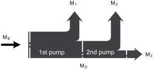
| Couple d'entrée | ME=M1+M2+M3 |
| ME < ME max | |
| Couple en traversée | MD=M2+M3 |
| MD < MD max |
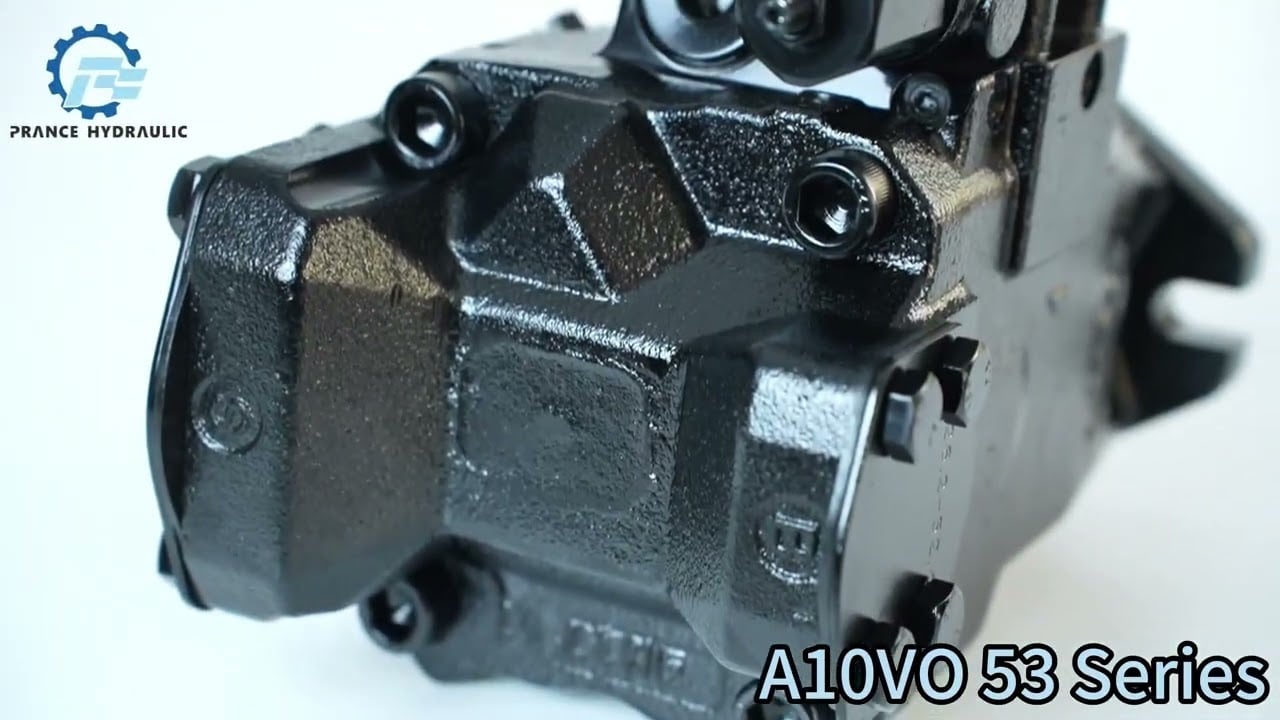
Watch A10VO Series 53 Product Video
Related Selection Resources
Request a A10VO Series 53 Quotation
Tell us your required configuration, quantity and application.
Produits associés
Compare related hydraulic pumps and confirm the complete configuration for your application.
Données techniques
| Taille | NG | 10 | 18 | 28 | 45 | 60 | 63 | 72 | 85 | 100 | ||
| Cylindrée géométrique par tour | Vg max | cm3 | 10.5 | 18 | 28 | 45 | 60 | 63 | 72 | 85 | 100 | |
| Vitesse de rotation
maximum1) |
à VGiga | nnom | tours par minute | 3600 | 3300 | 3000 | 26004) | 2700 | 2600 | 2600 | 2500 | 2300 |
| à Vg <Vg max 2) | nadm. max. | tours par minute | 4320 | 3960 | 3600 | 3120 | 3140 | 3140 | 3140 | 3000 | 2500 | |
| Flux | à nnom et VGiga | qv | L/min | 37 | 59 | 84 | 117 | 162 | 163 | 187 | 212 | 230 |
| à nE = 1500 tr/min | qvE | L/min | 15 | 27 | 42 | 68 | 90 | 95 | 108 | 128 | 150 | |
| Puissance | Avec Nnom, VGiga
et Δp = 250 bar |
P | kW | 16 | 25 | 35 | 49 | 65 | 68 | 77 | 89 | 96 |
| à nE= 1500 tr/min | PE | kW | 7 | 11 | 18 | 28 | 37 | 39 | 45 | 53 | 62 | |
| Couple | à VGiga
et Δp = 250 bar |
M | Rien | 42 | 71 | 111 | 179 | 238 | 250 | 286 | 338 | 398 |
| à VGiga
et Δp = 100 bar |
M | Rien | 17 | 29 | 45 | 72 | 95 | 100 | 114 | 135 | 159 | |
| Rigidité de rotation arbre d'entraînement | S | c | Nm/rad | 9200 | 11000 | 22300 | 37500 | 65500 | 65500 | 65500 | 143000 | 143000 |
| R | c | Nm/rad | - | 14800 | 26300 | 41000 | 69400 | 69400 | 69400 | 152900 | 152900 | |
| U | c | Nm/rad | 6800 | 8000 | 16700 | 30000 | 49200 | 49200 | 49200 | 102900 | 102900 | |
| W | c | Nm/rad | - | - | 19900 | 34400 | 54000 | 54000 | 54000 | 117900 | 117900 | |
| P | c | Nm/rad | 10700 | - | - | - | - | - | - | - | - | |
| Moment d'inertie du groupe tournant | JTW | Kgm2 | 0.0006 | 0.0009 | 0.0017 | 0.003 | 0.0056 | 0.0056 | 0.0056 | 0.012 | 0.012 | |
| Accélération angulaire maximale3) | α | rad/s2 | 8000 | 6800 | 5500 | 4000 | 3300 | 3300 | 3300 | 2700 | 2700 | |
| Volume du boîtier | V | L | 0.2 | 0.25 | 0.3 | 0.5 | 0.8 | 0.8 | 0.8 | 1 | 1 | |
| Poids sans entraînement traversant (approximatif)
Poids avec entraînement traversant (approximatif) |
m | kg | 8 | 11.5 | 15 | 18 | 22 | 22 | 22 | 36 | 36 | |
| - | 13 | 18 | 24 | 28 | 28 | 28 | 45 | 45 | ||||
Définir les caractéristiques de fonctionnement
| Flux | qv=(Vg ∙ n ∙ ηv) / 1000 | L/min |
| Couple | M=(Vg ∙ Δp) /(20 ∙ π ∙ ηhm) | Rien |
| Puissance | P=(2π ∙ M ∙ n)/60000=(qv ∙ Δp)/(600 ∙ ηt) | kW |
Clé
Vg Déplacement par révolution en [cm3]
Δp Pression différentielle [bar]
n Vitesse de rotation [tr/min]
ηv Efficacité volumétrique
ηhm Efficacité hydraulico-mécanique
ηt Efficacité totale (ηt= ηv*ηhm)
1) Les valeurs sont applicables :
- À une pression absolue pabdos = 1 bar à l'entrée d'aspiration S
- pour la plage de viscosité optimale à partir de Vopt = 36 à 16 mm2/s
- avec un fluide hydraulique à base d'huiles minérales
2)Voir le diagramme à la page 9 lors de l'augmentation de la vitesse jusqu'à nmax adm.
3)Les données sont valides pour des valeurs comprises entre la vitesse de rotation minimale requise et la vitesse maximale admissible. Cela s'applique aux stimuli externes (par exemple, moteur diesel 2 à 8 fois la fréquence de rotation, arbre de transmission deux fois la fréquence de rotation). La valeur limite n'est valable que pour une seule pompe. La capacité de charge des pièces de connexion doit être prise en compte.
Forces radiales et axiales admissibles sur l'arbre d'entraînement
| Taille | NG | 10 | 18 | 28 | 45 | 60/63 | 72 | 85 | 100 | ||
| Force radiale maximale à a/2 |
force radiale |
Fq max | N | 250 | 350 | 1200 | 1500 | 1700 | 1500 | 2000 | 2000 |
| Force axiale maximale |
force axiale |
±Fax max | N | 400 | 700 | 1000 | 1500 | 2000 | 1500 | 3000 | 3000 |
couples d'entrée et de transmission admissibles
| Taille | 10 | 18 | 28 | 45 | 60/63 | 72 | 85 | 100 | |||
| Couple à VGiga et Δp = 250 bar1) | Mmax | Rien | 42 | 71 | 111 | 179 | 250 | 321 | 338 | 398 | |
| Couple d'entrée maximal sur l'arbre d'entraînement2) | |||||||||||
| S | ME max | Rien | 126 | 124 | 198 | 319 | 630 | 630 | 1157 | 1157 | |
| ∅ | in | 3/4 | 3/4 | 7/8 | 1 | 1 1/4 | 1 1/4 | 1 1/2 | 1 1/2 | ||
| R | ME max | Rien | - | 160 | 250 | 400 | 650 | 650 | 1215 | 1215 | |
| ∅ | in | - | 3/4 | 7/8 | 1 | 1 1/4 | 1 1/4 | 1 1/2 | 1 1/2 | ||
| U | ME max | Rien | 60 | 59 | 105 | 188 | 306 | 306 | 628 | 628 | |
| ∅ | in | 5/8 | 5/8 | 3/4 | 7/8 | 1 | 1 | 1 1/4 | 1 1/4 | ||
| W | ME max | Rien | - | - | 140 | 220 | 396 | 383 | 650 | 650 | |
| ∅ | in | - | - | 3/4 | 7/8 | 1 | 1 | 1 1/4 | 1 1/4 | ||
| P | ME max | Rien | 90 | - | - | - | - | - | - | - | |
| ∅ | mm | 18 | - | - | - | - | - | - | - | ||
| Couple maximal en traversée | |||||||||||
| S | MD max | Rien | - | 108 | 160 | 319 | 484 | 484 | 698 | 698 | |
| R | MD max | Rien | - | 120 | 176 | 365 | 484 | 484 | 698 | - | |
| U | MD max | Rien | - | 59 | 105 | 188 | 306 | 306 | 628 | 628 | |
| W | MD max | Rien | - | - | 140 | 220 | 396 | 383 | 650 | 650 | |
Répartition des couples
| Couple à la première pompe | M1 |
| Couple à la deuxième pompe | M2 |
| Couple à la troisième pompe | M3 |
| Couple d'entrée | ME=M1+M2+M3 |
| ME < ME max | |
| Couple en traversée | MD=M2+M3 |
| MD < MD max |
1)Efficacité non prise en compte
2) For drive shafts with no radial force
