Wenzhou Prance Hydraulic Equipment Co., Ltd

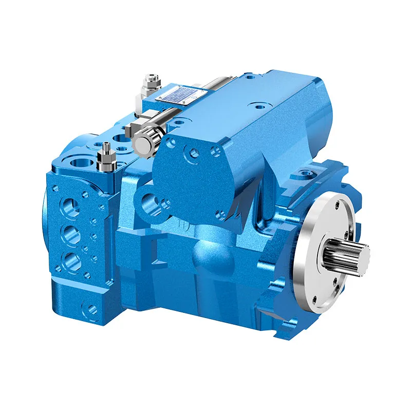


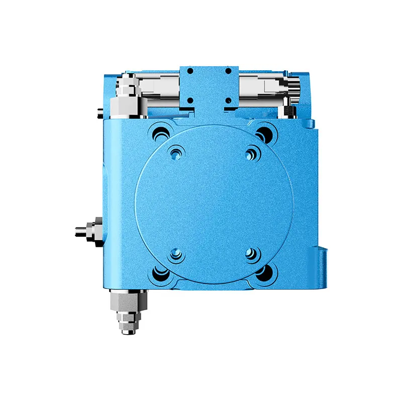


Closed Loop Variable Displacement Piston Pump AA4VG
1.Integrated auxliay pump for boost and piot oilsupply.
2.Flow direcion changes smoothy when the swashplate is moved through the neutral postion
3.High-pressure relief valves with integated boost function.
4.With adjustable pressure cut-off as standard
5.Through drive for mounting of further pumps up to same nominal size
6.Large variety of controls
Description détaillée
1.Integrated auxiliary pump for boost and pilot oil supply, which integrates the boost and pilot oil supply functions into a single component, effectively simplifying the overall hydraulic system structure, reducing installation space, and ensuring stable and reliable oil supply for both boost and pilot circuits, thus improving the operational stability of the entire equipment.
2.Flow direction changes smoothly when the swashplate is moved through the neutral position. This design avoids sudden pressure fluctuations and impact during flow direction switching, reduces mechanical wear of internal components, extends the service life of the pump, and ensures smooth and steady operation of the hydraulic system during forward and reverse operation.
3.High-pressure relief valves with integrated boost function, which not only play a role in overpressure protection to prevent damage to the system caused by excessive pressure but also integrate the boost function, realizing the integration of multiple functions, reducing the number of independent components, and lowering the system cost and maintenance difficulty.
4.With adjustable pressure cut-off as standard, allowing users to flexibly adjust the pressure cut-off value according to actual working conditions and load requirements, ensuring the pump operates within the safe pressure range, and adapting to different application scenarios to improve the versatility and applicability of the pump.
5.Through drive for mounting of further pumps up to same nominal size, providing a convenient and compact installation solution for expanding the hydraulic system. It enables the installation of additional pumps of the same nominal size without redesigning the drive structure, enhancing the expandability of the system and meeting the needs of large flow or multi-circuit oil supply.
6.Large variety of controls, including manual, hydraulic, electric and other control modes, which can be selected according to the actual control requirements of the equipment, realizing flexible and precise control of the pump, and adapting to different operating environments and control systems.
Sélection et DPX
Cette gamme de produits doit être choisie en fonction du circuit hydraulique approuvé. Confirmez le débit ou la cylindrée requis, la pression continue et de pointe, la vitesse d'entraînement, le type de commande, le fluide et l'interface d'installation avant la sélection finale.
Informations à inclure dans votre demande de devis
- Cylindrée ou débit requis à la vitesse de service
- Pression système continue et de pointe
- Vitesse d'entraînement, exigence de contrôle et type de circuit
- Bride de fixation, arbre, orifices, exigences en matière de fluide et de filtration
Ressources associées
Code source
| 01 | 02 | 03 | 04 | 05 | 06 | 07 | 08 | 09 | 10 | 11 | 12 | 13 | 14 | 15 | 16 | 17 | 18 | 19 | 20 | 21 | 22 | ||
| AA4V | G | D | / | 32 | - | N |
Unité à pistons axiaux
| 01 | Swashplate design, variable, nominal pressure 5800 psi (400 bar), maximum pressure 6500 psi (450 bar) | AA4V |
Mode de fonctionnement
| 02 | Pompe, circuit fermé | G |
Taille (NG)
| 03 | Cylindrée géométrique, voir " Données techniques " à la page 8 | in3/rev. | 1.71 | 2.44 | 3.42 | 4.33 | 5.49 | 7.63 |
| cm3/rev. | 28 | 40 | 56 | 71 | 90 | 125 |
Dispositif de commande
| 28 | 40 | 56 | 71 | 90 | 125 | |||||
| 04 | Sans module de commande | ● | ● | ● | ● | ● | ● | NV | ||
| Contrôle proportionnel, hydraulique | Pilot-pressure related p = 87 to 260 psi (6 to 18 bar) | ○ | ○ | ● | ● | ● | ● | HD3 | ||
| Servomécanisme mécanique | ● | ● | ● | ● | ● | ● | Devoir | |||
| Commande proportionnelle, électrique | U=12V | ● | ● | ● | ● | ● | ● | ÉP3 | ||
| U=24V | ● | ● | ● | ● | ● | ● | EP4 | |||
| Régulation à deux points, électrique | U=12V | ● | ● | ● | ● | ● | ● | EZ1 | ||
| U=24V | ● | ● | ● | ● | ● | ● | EZ2 | |||
| Commande automatique, liée à la vitesse | U=12V | ● | ● | ● | ● | ● | ● | DA1 | ||
| U=24V | ● | ● | ● | ● | ● | ● | DA2 | |||
| Hydraulic control, direct operated | ○ | ○ | ● | ● | ● | ● | DG | |||
| Commande électrique, à action directe,
deux détendeurs de pression |
U=12V | ● | ● | ● | ● | - | - | ET5 | ||
| U=24V | ● | ● | ● | ● | - | - | ET6 | |||
Coupure par pression
| 05 | Pressure cut-off (standard) | D |
Contacteur de position neutre
| 06 | Sans interrupteur de position neutre (sans code) | ● | |
| Interrupteur de position neutre (pour commande matérielle uniquement) | ● | L |
Limiteur de course mécanique
| 07 | Sans limiteur de course mécanique (sans code) | ● | |
| Limiteur de course mécanique, réglable de l'extérieur | ● | M |
Orifice de pression de la chambre de manœuvre
| 28 | 40 | 56 | 71 | 90 | 125 | |||
| 08 | |Without stroking chamber pressure port X3, X4 (without code) | ● | ● | ● | ● | ● | ● | |
| Port de pression de la chambre de manœuvre X3, X4 | ○ | ○ | ● | ● | ● | ● | T | |
vanne de régulation DA
| NV | HD | Devoir | DG | DA | EP | Facile | ||||
| 09 | Sans vanne de régulation DA | ● | ● | ● | ● | - | ● | ● | 1 | |
| soupape de commande DA, réglage fixe | ● | ● | ● | ● | ● | - | 2 | |||
| DA control valve, mechanically adjustable with position lever | sens d'actionnement, horaire | - | ● | ● | ● | ● | ● | - | 3R | |
| sens d'actionnement,
dans le sens inverse des aiguilles d'une montre |
- | ● | ● | ● | ● | ● | - | 3L | ||
| distributeur DA, réglage fixe, orifices pour dispositif de commande pilote | - | ○ | ○ | - | ○ | ○ | - | 7 | ||
| DA control valve, fixed setting and
brake inch valve mounted, control with brake fluid |
à base d'huile minérale | - | - | - | - | ● | - | - | 8 | |
•= available ○= on request -= not available  = programme préféré
Séries
| 10 | Série 3, indice 2 | 32 |
Sens de rotation
| 11 | Vu sur l'arbre de transmission | dans le sens des aiguilles d'une montre | R |
| dans le sens inverse des aiguilles d'une montre | L |
Matériau d'étanchéité
| 12 | NBR (nitrile rubber), shaft seal in FKM (fluoroelastomer) | N |
Arbre de transmission
| 28 | 40 | 56 | 71 | 90 | 125 | ||||
| 13 | Arbre cannelé
ANSIB92.1a |
pour pompe unique | ● | ● | ● | ● | ● | ● | S |
| for combination pump - 1st pump | _1) | _1) | ● | ● | _1) | ● | T | ||
| only for combination pump -2nd pump | - | ● | - | - | ● | - | U | ||
Bride de fixation
| 28 | 40 | 56 | 71 | 90 | 125 | ||||
| 14 | SAEJ744 | à deux trous | ● | ● | ● | - | - | - | C |
| 2+4 trous | - | - | - | ● | ● | ● | F | ||
Port en eau profonde
| 28 | 40 | 56 | 71 | 90 | 125 | ||||
| 15 | SAE working port A and B, top and bottom | Orifice d'aspiration S inférieur | - | ● | ● | ● | ● | ● | 52 |
| SAE working port A and B, top and bottom | Orifice d'aspiration S haut | - | ○ | ● | - | - | ○ | 53 | |
| SAE working port A and B, same side right2) | Orifice d'aspiration S inférieur | ● | - | - | - | - | - | 60 | |
| SAE working port A and B, same side left2) | Orifice d'aspiration S inférieur | - | - | - | ● | - | - | ||
| SAE working port A and B, same side right2) | Orifice d'aspiration S haut | - | - | - | - | - | ○ | 63 | |
Boost pump
| 16 | Without integrated boost pump | sans entraînement direct | N |
| with through drive | K | ||
| Integrated boost pump | with and without through drive | F |
Through drives3)
| 28 | 40 | 56 | 71 | 90 | 125 | ||||
| 17 | Without through drive, versions N and F (no. 16) only | ● | ● | ● | ● | ● | ● | 00 | |
| Flange SAE J7444) | Moyeu pour arbre cannelé | ||||||||
| 82-2 (A) | 5/8 in 9T 16/32DP5) | ● | ● | ● | ● | ● | ● | 01 | |
| 101-2 (B) | 7/8 in 13T 16/32DP5) | ● | ● | ● | ● | ● | ● | 02 | |
| 1in 15T 16/32DP5) | ● | ● | ● | ● | ● | ● | 04 | ||
| 127-2 (C)6) | 1 1/4 in 14T 12/24DP5) | - | - | ● | ● | ● | ● | 07 | |
| 152-2/4 (D) | 13/4 in 13T 8/16DP5) | - | - | - | - | - | ● | 69 | |
•= available ○= on request -= not available = programme préféré
1) Standard for combination pump - 1st pump: Shaft S
2) Only possible without attachment filter
3) Specifications for version with integrated boost pump, please contact us for version without boost pump
4) 2 = 2-hole; 4 = 4-hole
5) Hub for splined shaft to ANSI B92.1a
6) NG90 to 125 with additional 4-hole-flange (127-4)
High-pressure relief valve
| Setting range Δp | 28 | 40 | 56 | 71 | 90 | 125 | ||||
| 18 | High pressure relief valve, pilot operated | 1450 to 6100 psi
(100 to 420 bar) |
with bypass | - | - | - | ● | ● | ● | 1 |
| High-pressure relief valve, direct operated,
fixed setting |
3600 to 6100 psi
(250 to 420 bar) |
without bypass | ● | ● | ● | - | - | - | 3 | |
| with bypass | ● | ● | ● | - | - | - | 4 | |||
| 1450 to 3600 bar
(100 to 250 bar) |
without bypass | ● | ● | ● | - | - | - | 5 | ||
| with bypass | ● | ● | ● | - | - | - | 6 | |||
Filtration boost circuit/external boost pressure supply
| 28 | 40 | 56 | 71 | 90 | 125 | |||
| 19 | Filtration in the boost pump suction line | ● | ● | ● | ● | ● | ● | S |
| Filtration in the boost pump pressure line
Ports for external boost circuit filtration (Fe and Fa) |
● | ● | ● | ● | ● | ● | D | |
| Mounted cold start valve and ports for external boost circuit filtration | - | ● | ● | - | - | - | K | |
| Attachment filter with cold start valve | - | ● | ● | ● | ● | ● | F | |
| Attachment filter with cold start valve and visual contamination indicator | - | ● | ● | ● | ● | ● | P | |
| Attachment filter with cold start valve and electric contamination indicator | - | ● | ● | ● | ● | ● | B | |
| External boost pressure supply (version without integrated boost pump - NO0, K...) | ● | ● | ● | ● | ● | ● | E | |
Swivel angle sensor
| 28 | 40 | 56 | 71 | 90 | 125 | |||
| 20 | Without swivel angle sensor (without code) | ● | ● | ● | ● | ● | ● | |
| Electric swivel angle sensor7) | ○ | ○ | ● | ○ | ○ | ○ | R | |
Connector for solenoids8)
| 21 | Without connector (without code), only for purely hydraulic control | ● | ||
| DEUTSCH molded connector, 2-pin | without suppressor diode | ● | P | |
| with suppressor diode (only for EZ and DA) | ● | Q | ||
Standard / special version
| 22 | Standard version | sans code | |
| combined with attachment part or attachment pump | -K | ||
| Special version | -S | ||
| combined with attachment part or attachment pump | -SK |
•= available ○= on request -= not available = programme préféré
Notice
▶Note the project planning notes on page 68.
▶In addition to the type code, please specify the relevant technical data when placing your order.
7)Please contact us if the swivel angle sensor is used for control
8) Connectors for other electric components may deviate
Données techniques
| Taille | NG | 28 | 40 | 56 | 71 | 90 | 125 | |||
| Cylindrée géométrique par tour | Vg max
|
in3 | 1.71 | 2.44 | 3.42 | 4.33 | 5.49 | 7.63 | ||
| variable pump | cm3 | 28 | 40 | 56 | 71 | 90 | 125 | |||
| boost pump (at p = 290 psi (20 bar)) | Vg Sp
|
in3 | 0.37 | 0.52 | 0.71 | 1.20 | 1.20 | 1.73 | ||
| cm3 | 6.1 | 8.6 | 11.6 | 19.6 | 19.6 | 28.3 | ||||
| Rotational speed1) | maximum at VGiga | nnom | tours par minute | 4250 | 4000 | 3600 | 3300 | 3050 | 2950 | |
| limited, maximum2) | nmax1 | tours par minute | 4500 | 4200 | 3900 | 3600 | 3300 | 3250 | ||
| intermittent, maximum3) | nmax2 | tours par minute | 5000 | 5000 | 4500 | 4100 | 3800 | 3450 | ||
| minimum | nmin | tours par minute | 500 | 500 | 500 | 500 | 500 | 500 | ||
| Flux | at nnom et VGiga | qv | gpm | 31.4 | 42.3 | 53.4 | 61.8 | 72.6 | 94 | |
| L/min | 119 | 160 | 202 | 234 | 275 | 356 | ||||
| Puissance4) | at nnom, VGiga and | Δp = 5800 psi | P | hp | 106 | 143 | 180 | 209 | 245 | 319 |
| Δp =400 bar | P | kW | 79 | 107 | 134 | 156 | 183 | 238 | ||
| Torque4) | at VGiga and | Δp =5800 psi | T | Ib-ft | 131 | 188 | 263 | 333 | 423 | 587 |
| Δp =400 bar | T | Rien | 178 | 255 | 357 | 452 | 573 | 796 | ||
| Ap =1450 psi | T | lb-ft | 33 | 47 | 66 | 83 | 105 | 147 | ||
| Ap =100 bar | T | Rien | 45 | 64 | 89 | 113 | 143 | 199 | ||
| Rotary stiffness of drive shaft | S | c | lb-ft/rad | 23159 | 50892 | 59595 | 72871 | 116609 | 161010 | |
| kNm/rad | 31.4 | 69 | 80.8 | 98.8 | 158.1 | 218.3 | ||||
| T | c | lb-ft/rad | - | - | 70068 | 89171 | - | 185939 | ||
| kNm/rad | - | - | 95 | 120.9 | - | 252.1 | ||||
| U | c | lb-ft/rad | - | 37468 | - | - | 79362 | - | ||
| kNm/rad | - | 50.8 | - | - | 107.6 | - | ||||
| Moment of inertia for rotary group | JTW | lbs-ft2 | 0.0522 | 0.0902 | 0.1566 | 0.2302 | 0.3536 | 0.5505 | ||
| kgm2 | 0.0022 | 0.0038 | 0.0066 | 0.0097 | 0.0149 | 0.0232 | ||||
| Maximum angular acceleration5) | α | rad/s2 | 38000 | 30000 | 24000 | 21000 | 18000 | 14000 | ||
| Case volume | V | gal | 0.24 | 0.29 | 0.40 | 0.34 | 0.40 | 0.55 | ||
| I | 0.9 | 1.1 | 1.5 | 1.3 | 1.5 | 2.1 | ||||
| Weight (without through drive) approx. | m | Ibs | 64 | 68 | 84 | 110 | 132 | 176 | ||
| Kg | 29 | 31 | 38 | 50 | 60 | 80 | ||||
Notice
▶Theoretical values, without efficiency and tolerances;values rounded
▶Operation above the maximum values or below the minimum values may result in a loss of function, a reduced service life or in the destruction of the axial piston unit. Bosch Rexroth recommend testing the loads by means of experiment or calculation / simulation and comparison with the permissible values.
Determining the operating characteristics
| Flux | qv=(Vg ∙ n ∙ ηv) /231 | gpm | (Vg ∙ n ∙ ηv) / 1000 | L/min |
| Torque | T=(Vg ∙ Δp) /(24 ∙ π ∙ ηhm) | lb-ft | (Vg ∙ Δp) /(24 ∙ π ∙ ηhm) | Rien |
| Puissance | P=(2π ∙ T ∙ n)/33000=(qv ∙ Δp)/(1714 ∙ ηt) | HP | (2π ∙ M ∙ n)/60000=(qv ∙ Δp∙ ηt)/600 | kW |
Key
Vg Displacement per revolution [in3(cm3)]
Δp Differential pressure [psi(bar)]
n Rotational speed [rpm]
ηv Volumetric efficiency
ηhm Hydraulic-mechanical efficiency
ηt Total efficiency (ηt= ηv*ηhm)
1)The values are applicable:
- for the optimum viscosity range from Vopt = 170 to 82 SUS(36 to 16 mm2/s)
- for hydraulic fluid based on mineral oils (for HF hydraulic fluids,observe the technical data in 90225)
2)Valid at half corner power (e.g. at VGiga and pN/2)
3) Valid at Δp = 1000 to 2200 psi (70 to 150 bar) or Δp < 4350 psi(300 bar) and t < 0.1 s
4)Without boost pump
5)The data are valid for values between the minimum required and maximum permissible rotational speed.
Valid for external excitation (e.g. diesel engine 2 to 8 times rotary frequency, cardan shaft twice the rotary frequency).
The limit value is only valid for a single pump.
The load capacity of the connecting parts must be considered.
Permissible radial and axial forces on the drive shaft
▼Splined shaft ANSI B92.1a
| Taille | NG | 28 | 40 | 40 | 56 | 56 | 71 | ||
| Arbre de transmission | in | 1 | 1 | 1 1/4 | 1 1/4 | 1 3/8 | 1 1/4 | ||
| Maximum radial force at distance a(from shaft collar) | 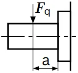 |
Fq max | lbf | 671 | 958 | 766 | 1073 | 975 | 1360 |
| N | 2983 | 4261 | 3409 | 4772 | 4338 | 6050 | |||
| a | in | 0.75 | 0.75 | 0.94 | 0.94 | 0.94 | 0.94 | ||
| mm | 19 | 19 | 24 | 24 | 24 | 24 | |||
| Maximum axial force | 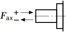 |
+Fax max | lbf | 350 | 477 | 477 | 654 | 654 | 954 |
| N | 1557 | 2120 | 2120 | 2910 | 2910 | 4242 | |||
| -Fax max | lbf | 94 | 198 | 198 | 355 | 355 | 620 | ||
| N | 417 | 880 | 880 | 1490 | 1490 | 2758 | |||
| Taille | NG | 71 | 90 | 90 | 125 | 125 | ||
| Arbre de transmission | in | 1 3/8 | 1 1/4 | 1 3/4 | 1 3/4 | 2 | ||
| Maximum radial force at distance a(from shaft collar) | |
Fq max | lbf | 1236 | 1724 | 1232 | 1711 | 1497 |
| N | 550 | 7670 | 5478 | 7609 | 6658 | |||
| a | in | 0.94 | 0.94 | 1.32 | 1.32 | 1.57 | ||
| mm | 24 | 24 | 33.5 | 33.5 | 40 | |||
| Maximum axial force | |
+Fax max | lbf | 954 | 973 | 973 | 1361 | 1361 |
| N | 4242 | 4330 | 4330 | 6053 | 6053 | |||
| -Fax max | lbf | 620 | 600 | 600 | 797 | 797 | ||
| N | 2758 | 2670 | 2670 | 3547 | 3547 | |||
Notice
▶The axial and radial forces generally influence the service life of the bearings.
▶Special requirements apply in the case of belt drive and cardan shaft. Please contact u
| Taille | NG | 28 | 40 | 56 | 71 | 90 | 125 | |||
| Torque at Vg max and | Δp = 5800 psi1) | T | lb-ft | 131 | 188 | 263 | 333 | 423 | 587 | |
| Δp = 400 bar1) | T | Rien | 178 | 255 | 357 | 452 | 573 | 796 | ||
| Maximum input torque
at drive shaft2) ANSI B92.1a (SAE J744) |
S | TE max | lb-ft | 232 | 444 | 444 | 444 | 1210 | 1210 | |
| Rien | 314 | 602 | 602 | 602 | 1640 | 1640 | ||||
| in | 1 | 1 1/4 | 1 1/4 | 1 1/4 | 1 3/4 | 1 3/4 | ||||
| T | TE max | lb-ft | - | - | 715 | 715 | - | 1969 | ||
| Rien | - | - | 970 | 970 | - | 2670 | ||||
| in | - | - | 1 3/8 | 1 3/8 | - | 2 | ||||
| U3) | TE max | lb-ft | - | 232 | - | - | 444 | - | ||
| Rien | - | 314 | - | - | 602 | - | ||||
| in | - | 1 | - | - | 1 1/4 | - | ||||
| Maximum through-drive torque4) | TD max | lb-ft | 170 | 232 | 384 | 487 | 606 | 819 | ||
| Rien | 231 | 314 | 521 | 660 | 822 | 1110 | ||||
Distribution of torques

| Torque at 1st pump | T1 |
| Torque at 2nd pump | T2 |
| Torque at 3rd pump | T3 |
| Input torque | TE=T1+T2+T3 |
| TE < TE max | |
| Through∙drive torque | TD=T2+T3 |
| TD < TD max |
1) Efficiency not considered
2) For drive shafts free of radial force
3) Shaft "U" is only permitted as drive shaft on the 2nd pump on a combination pump of the same size.
4)Note maximum input torque for shaft S!